Specifications
Absolute maximum ratings are those beyond which damage to the device may occur.
Prolonged operation between the operational specifications and absolute maximum ratings is not intended and may cause permanent device degradation.
Absolute Maximum Ratings
|
Parameter |
Min |
Max |
Units |
|
Supply voltage |
-0.3 |
3.6 |
V |
|
Data input voltage |
-0.3 |
3.465 |
V |
|
Control input voltage |
-0.3 |
4.0 |
V |
|
Damage Threshold |
3.4 |
--- |
dBm |
This table shows the environmental specifications for the product.
|
Parameter |
Min |
Max |
Units |
|
Storage temperature |
-40 |
85 |
°C |
This section shows the range of values for normal operation. The host board power supply filtering should be designed as recommended in the SFF Committee Spec.
|
Parameter |
Min |
Typ |
Max |
Units |
Notes |
|
Supply voltage (Vcc) |
3.135 |
3.3 |
3.465 |
V |
--- |
|
Power consumption 200Gb/s end |
--- |
4.5 |
5.0 |
W |
--- |
|
Power consumption 100Gb/s end |
--- |
3.0 |
3.5 |
W |
--- |
|
Supply noise tolerance (10Hz – 10MHz) |
66 |
--- |
--- |
mVpp |
--- |
|
Operating case temperature |
0 |
--- |
70 |
°C |
--- |
|
Operating relative humidity |
5 |
--- |
85 |
% |
--- |
|
Parameter (per lane) |
Min |
Typ |
Max |
Units |
|
Signaling rate |
-100 ppm |
53.125 |
+100 ppm |
GBd |
|
Differential data input swing at TP1a |
TBD |
--- |
900 |
mVpp |
|
Differential data output swing at TP4 |
--- |
--- |
900 |
mVpp |
|
Near-end ESMW |
0.265 |
--- |
--- |
UI |
|
Near-end output eye height |
70 |
--- |
--- |
mVpp |
|
Output transition time, 20% to 80% |
9.5 |
--- |
--- |
ps |
Notes:
Multiple clock domains are supported only on line-side Rx. Host side Rx supports a single clock domain only.
QSFP Tx CDR lock can only occur if Tx lane 4 is transmitting data.
This product is compatible with ESD levels in typical data center operating environments and certified in accordance with the standards listed in the Regulatory Compliance Section. The product is shipped with protective caps on all connectors to protect it during shipping. In normal handling and operation of high-speed cables and optical transceivers, ESD is of concern during insertion into the QSFP cage of the server/switch. Hence, standard ESD handling precautions must be observed. These include use of grounded wrist/shoe straps and ESD floor wherever a cable/transceiver is extracted/inserted. Electrostatic discharges to the exterior of the host equipment chassis after installation are subject to system level ESD requirements.
The transceiver can be damaged by exposure to current surges and over voltage events. Take care to restrict exposure to the conditions defined in Absolute Maximum Ratings. Observe normal handling precautions for electrostatic discharge-sensitive devices. The transceiver is shipped with dust caps on both the electrical and the optical port. The cap on the optical port should always be in place when there is no fiber cable connected. The optical connector has a recessed connector surface which is exposed whenever it has no cable nor cap.
Prior to insertion of the fiber cable, clean the cable connector to prevent contamination from it. The dust cap ensures that the optics remain clean and no additional cleaning should be needed. In the event of contamination, standard cleaning tools and methods should be used. Liquids must not be applied.
For configurations tested with the AOCs please refer to the system level product (SLP) qualification report.
The AOC supports rate select, which is controlled by writing to registers 0x57-0x58. Two bits are assigned for each receiver lane in byte 0x57 (87dec, Rxn_Rate_Select) and two bits for each transmitter lane in byte 0x58 (88dec, Txn_Rate_Select) to specify up to four bitrates, as defined in SFF-8636 Rev 2.9.2 Table 6-5 XN_RATE_SELECT ENCODINGS. All four lanes are required to have the same rate select value.
The below table specifies the rate for each rate select setting.
Rate Select Encodings
|
Rate Select Value |
Operating Rate (GBd) |
|
01 |
10.31250 NRZ |
|
10 |
25.78125 NRZ |
|
11 |
26.56250 PAM4 |
|
Parameter |
Value |
Units |
|
|
Diameter |
3 +/-0.2 |
mm |
|
|
Minimum bend radius |
30 |
mm |
|
|
Length tolerance |
length < 5 m |
+300 /-0 |
mm |
|
5 m ≤ length < 50 m |
+500 / -0 |
||
|
50 m ≤ length |
+1000 /-0 |
||
|
Cable color |
Aqua |
--- |
|
Option 1
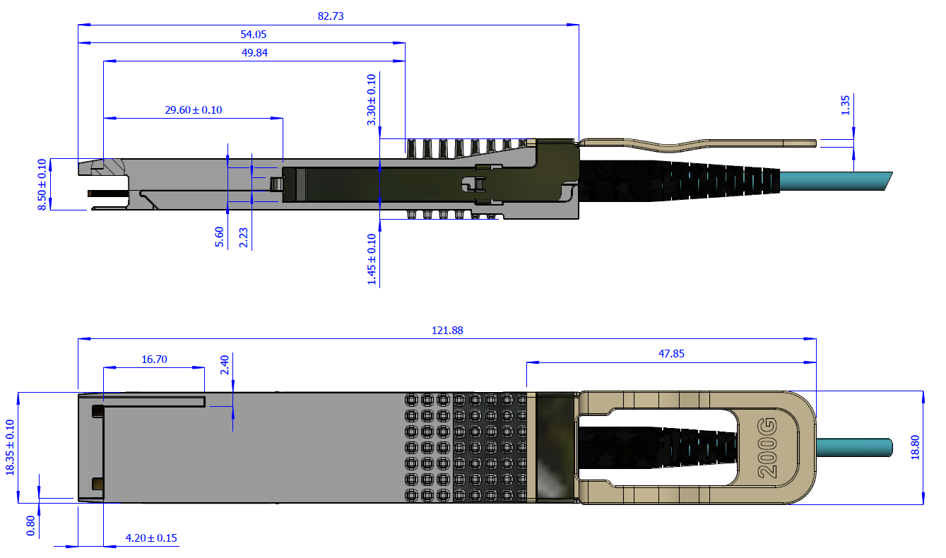
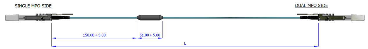
Splicing Point and Cable Length
Option 2
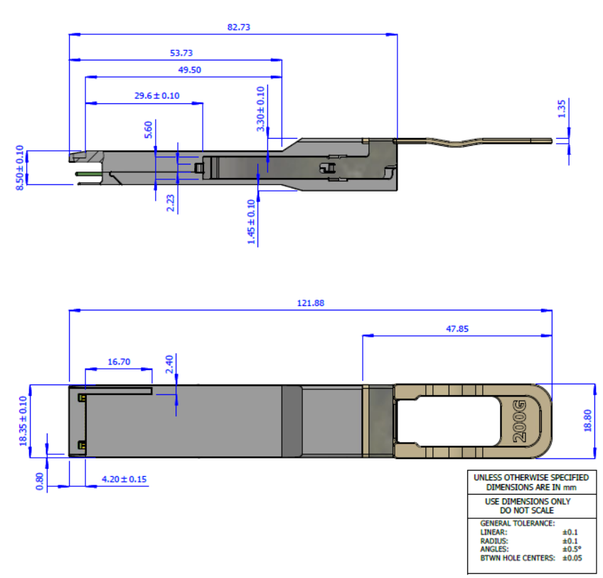
Splicing Point and Cable Length
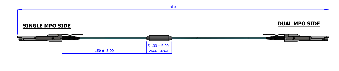
Option 1+2 refers to parts with slightly different designs and may have different pull tab shape, color, and transceiver top.
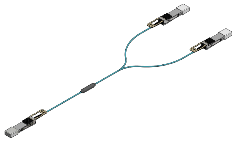
Connectivity Schematic
|
200Gb/s Side |
2x100Gb/s Side |
|
Port 1 |
|
|
TX1 |
RX1 |
|
RX1 |
TX1 |
|
TX2 |
RX2 |
|
RX2 |
TX2 |
|
Port 2 |
|
|
TX3 |
RX1 |
|
RX3 |
TX1 |
|
TX4 |
RX2 |
|
RX4 |
TX2 |
The following labels are applied on the AOC backshells:
200Gb/s Backshell Label
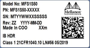
(sample illustration)
100Gb/s Backshell Label
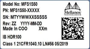
(sample illustration)
Images are for illustration purposes only. Product labels, colors, and lengths may vary.
Backshell Label Legend
|
Symbol |
Meaning |
Notes |
|
|
PN – Part Number |
|||
|
xx |
Length |
Meter |
|
|
SN – Serial Number |
|||
|
MT |
Manufacturer name |
2 characters, e.g. MT |
|
|
YY |
Year of manufacturing |
2 digits |
|
|
WW |
Week of manufacturing |
2 digits |
|
|
XX |
Manufacturer site |
2 characters |
|
|
SSSSS |
Serial number |
5 digits for serial number, starting from 00001. Reset at start of week to 00001. |
|
|
Miscellaneous |
|||
|
ZZ |
HW and SW revision |
2 alpha-numeric characters |
|
|
YYYY |
Year of manufacturing |
4 digits |
|
|
MM |
Month of manufacturing |
2 digits |
|
|
DD |
Day of manufacturing |
2 digits |
|
|
COO |
Country of origin |
E.g. China or Malaysia |
|
|
XXm |
Cable length |
Meter |
|

|
Quick response code |
Serial number (MTYYWWXXSSSSS) |
|
The following label is applied on the cable’s jacket:
Fiber Cable Jacket Label
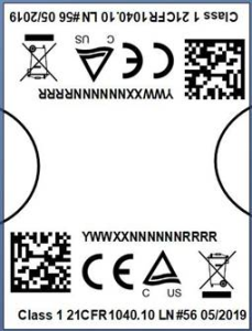
(sample illustration)
Note:The serial number and barcode are for internal use only. Different layouts of this label apply to different production series. It has no effect on the cable's performance nor function.
Splitter Cable Labels Identifying the 2 QSFP56 Tails
(sample illustration)
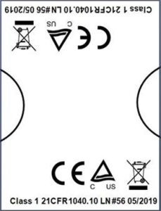
The laser module is classified as class I according to IEC 60825-1, IEC 60825-2 and 21 CFR 1040 (CDRH).
Safety: CB, cTUVus, CE
EMC: CE, FCC, ICES, RCM, VCCI
Ask your NVIDIA FAE for a zip file of the certifications for this product.
This equipment has been tested and found to comply with the limits for a Class A digital device, pursuant to part 15 of the FCC Rules. These limits are designed to provide reasonable protection against harmful interference when the equipment is operated in a commercial environment. This equipment generates, uses, and can radiate radio frequency energy and, if not installed and used in accordance with the instruction manual, may cause harmful interference to radio communications. Operation of this equipment in a residential area is likely to cause harmful interference in which case the user will be required to correct the interference at his own expense.