RDMA over Converged Ethernet (RoCE)
Remote Direct Memory Access (RDMA) is the remote memory management capability that allows server-to-server data movement directly between application memory without any CPU involvement. RDMA over Converged Ethernet (RoCE) is a mechanism to provide this efficient data transfer with very low latencies on lossless Ethernet networks. With advances in data center convergence over reliable Ethernet, ConnectX® Ethernet adapter cards family with RoCE uses the proven and efficient RDMA transport to provide the platform for deploying RDMA technology in mainstream data center application at 10GigE and 40GigE link-speed. ConnectX® Ethernet adapter cards family with its hardware offload support takes advantage of this efficient RDMA transport (InfiniBand) services over Ethernet to deliver ultra-low latency for performance-critical and transaction-intensive applications such as financial, database, storage, and content delivery networks.
When working with RDMA applications over Ethernet link layer the following points should be noted:
The presence of a Subnet Manager (SM) is not required in the fabric. Thus, operations that require communication with the SM are managed in a different way in RoCE. This does not affect the API but only the actions such as joining the multicast group, that need to be taken when using the API
Since LID is a layer 2 attribute of the InfiniBand protocol stack, it is not set for a port and is displayed as zero when querying the port
With RoCE, the alternate path is not set for RC QP. Therefore, APM (another type of High Availability and part of the InfiniBand protocol) is not supported
Since the SM is not present, querying a path is impossible. Therefore, the path record structure must be filled with relevant values before establishing a connection. Hence, it is recommended working with RDMA-CM to establish a connection as it takes care of filling the path record structure
VLAN tagged Ethernet frames carry a 3-bit priority field. The value of this field is derived from the IB SL field by taking the 3 least significant bits of the SL field
RoCE traffic is not shown in the associated Ethernet device's counters since it is offloaded by the hardware and does not go through Ethernet network driver. RoCE traffic is counted in the same place where InfiniBand traffic is counted; /sys/class/infiniband/<device>/ports/<port number>/counters/
RoCE encapsulates IB transport in one of the following Ethernet packets:
RoCEv1 - dedicated ether type (0x8915)
RoCEv2 - UDP and dedicated UDP port (4791)
RoCEv1 and RoCEv2 Protocol Stack
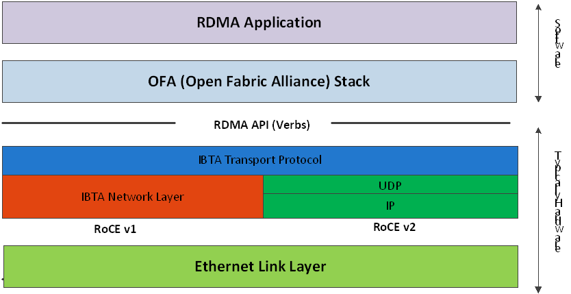
RoCEv1
RoCE v1 protocol is defined as RDMA over Ethernet header (as shown in the figure above). It uses ethertype 0x8915 and can be used with or without the VLAN tag. The regular Ethernet MTU applies on the RoCE frame.
RoCEv2
A straightforward extension of the RoCE protocol enables traffic to operate in IP layer 3 environments. This capability is obtained via a simple modification of the RoCE packet format. Instead of the GRH used in RoCE, IP routable RoCE packets carry an IP header which allows traversal of IP L3 Routers and a UDP header (RoCEv2 only) that serves as a stateless encapsulation layer for the RDMA Transport Protocol Packets over IP.
The proposed RoCEv2 packets use a well-known UDP destination port value that unequivocally distinguishes the datagram. Similar to other protocols that use UDP encapsulation, the UDP source port field is used to carry an opaque flow-identifier that allows network devices to implement packet forwarding optimizations (e.g. ECMP) while staying agnostic to the specifics of the protocol header format.
Furthermore, since this change exclusively affects the packet format on the wire, and due to the fact that with RDMA semantics packets are generated and consumed below the AP, applications can seamlessly operate over any form of RDMA service, in a completely transparent way.
Both RoCEv1 and RoCEv2 are supported by default; the driver associates all GID indexes to RoCEv1 and RoCEv2, thus, a single entry for each RoCE version.
For further information, please refer to Recommended Network Configuration Examples For RoCE Deployment community post.
GID table entries are created whenever an IP address is configured on one of the Ethernet devices of the NIC's ports. Each entry in the GID table for RoCE ports has the following fields:
GID value
GID type
Network device
The GID table is occupied with two GIDs, both with the same GID value but with different types. The network device in an entry is the Ethernet device with the IP address that GID is associated with. The GID format can be of 2 types; IPv4 and IPv6. IPv4 GID is an IPv4-mapped IPv6 address, while IPv6 GID is the IPv6 address itself. Layer 3 header for packets associated with IPv4 GIDs will be IPv4 (for RoCEv2) and IPv6/GRH for packets associated with IPv6 GIDs and IPv4 GIDs for RoCEv1.
GID Table in sysfs
GID table is exposed to userspace via sysfs
GID values can be read from:
/sys/
class/infiniband/{device}/ports/{port}/gids/{index}
GID type can be read from:
/sys/
class/infiniband/{device}/ports/{port}/gid_attrs/types/{index}
GID net_device can be read from:
/sys/
class/infiniband/{device}/ports/{port}/gid_attrs/ndevs/{index}
Setting the RoCE Mode for a Queue Pair (QP)
Setting RoCE mode for devices that support two RoCE modes is different for RC/UC QPs (connected QP types) and UD QP.
To modify an RC/UC QP (connected QP) from INIT to RTR, an Address Vector (AV) must be given. The AV, among other attributes, should specify the index of the port's GID table for the source GID of the QP. The GID type in that index will be used to set the RoCE type of the QP.
Setting RoCE Mode of RDMA_CM Applications
RDMA_CM interface requires only the active side of the peer to pass the IP address of the passive side. The RDMA_CM decides upon the source GID to be used and obtains it from the GID table. Since more than one instance of the GID value is possible, the lookup should be also according to the GID type. The type to use for the lookup is defined as a global value of the RDMA_CM module. Changing the value of the GID type for the GID table lookups is done using the cma_roce_mode script.
To print the current RoCE mode for a device port:
cma_roce_mode -d <dev> -p <port>
To set the RoCE mode for a device port:
cma_roce_mode -d <dev> -p <port> -m <1|2>
GID Table Example
The following is an example of the GID table.
DEV | PORT | INDEX | GID | IPv4 | Type | Netdev |
mlx5_0 | 1 | 0 | fe80:0000:0000:0000:ba59:9fff:fe1a:e3ea | v1 | p4p1 | |
mlx5_0 | 1 | 1 | fe80:0000:0000:0000:ba59:9fff:fe1a:e3ea | v2 | p4p1 | |
mlx5_0 | 1 | 2 | 0000:0000:0000:0000:0000:ffff:0a0a:0a01 | 10.10.10.1 | v1 | p4p1 |
mlx5_0 | 1 | 3 | 0000:0000:0000:0000:0000:ffff:0a0a:0a01 | 10.10.10.1 | v2 | p4p1 |
mlx5_1 | 1 | 0 | fe80:0000:0000:0000:ba59:9fff:fe1a:e3eb | v1 | p4p2 | |
mlx5_1 | 1 | 1 | fe80:0000:0000:0000:ba59:9fff:fe1a:e3eb | v2 | p4p2 |
where:
Entries on port 1 index 0/1 are the default GIDs, one for each supported RoCE type
Entries on port 1 index 2/3 belong to IP address 192.168.1.70 on eth1
Entries on port 1 index 4/5 belong to IP address 193.168.1.70 on eth1.100
Packets from a QP that is associated with these GID indexes will have a VLAN header (VID=100)
Entries on port 1 index 6/7 are IPv6 GID. Packets from a QP that is associated with these GID indexes will have an IPv6 header
In order to function reliably, RoCE requires a form of flow control. While it is possible to use global flow control, this is normally undesirable, for performance reasons.
The normal and optimal way to use RoCE is to use Priority Flow Control (PFC). To use PFC, it must be enabled on all endpoints and switches in the flow path.
For further information, please refer to RoCE Over L2 Network Enabled with PFC User Guide:
Configuring SwitchX® Based Switch System
To enable RoCE, the SwitchX should be configured as follows:
Ports facing the host should be configured as access ports, and either use global pause or Port Control Protocol (PCP) for priority flow control
Ports facing the network should be configured as trunk ports, and use Port Control Protocol (PCP) for priority flow control
For further information on how to configure SwitchX, please refer to SwitchX User Manual
To install and load the driver:
Install MLNX_OFED (See Installation section for further details).
RoCE is installed as part of mlx5 and other modules upon driver's installation.WarningThe list of the modules that will be loaded automatically upon boot can be found in the configuration file /etc/infiniband/openib.conf.
Query for the device's information. Example:
ibv_devinfo MLNX_OFED_LINUX-
5.0-2.1.8.0:Display the existing MLNX_OFED version.
ofed_info -s hca_id: mlx5_0 transport: InfiniBand (
0) fw_ver:16.28.0578node_guid: ec0d:9a03:0044:3764sys_image_guid: ec0d:9a03:0044:3764vendor_id:0x02c9vendor_part_id:4121hw_ver:0x0board_id: MT_0000000009 phys_port_cnt:1port:1state: PORT_ACTIVE (4) max_mtu:4096(5) active_mtu:1024(3) sm_lid:0port_lid:0port_lmc:0x00link_layer: Ethernet
Output Notes:
The port's state is: Ethernet is in PORT_ACTIVE state | The port state can also be obtained by running the following command: # cat /sys/class/infiniband/mlx5_0/ports/1/state 4: ACTIVE |
link_layer parameter shows that port 1 is Ethernet | The link_layer can also be obtained by running the following command: # cat /sys/class/infiniband/mlx5_0/ports/1/link_layer Ethernet |
The fw_ver parameter shows that the firmware version is 16.28.0578. | The firmware version can also be obtained by running the following command: # cat /sys/class/infiniband/mlx5_0/fw_ver 16.28.0578 |
Associating InfiniBand Ports to Ethernet Ports
The mlx5_ib driver holds a reference to the net device for getting notifications about the state of the port, as well as using the mlx5_core driver to resolve IP addresses to MAC that are required for address vector creation. However, RoCE traffic does not go through the mlx5_core driver; it is completely offloaded by the hardware.
            # ibdev2netdev
mlx5_0 port 1 <===> eth2
#
Configuring an IP Address to the netdev Interface
To configure an IP address to the netdev interface:
Configure an IP address to the netdev interface on both sides of the link.
# ifconfig eth2
20.4.3.220# ifconfig eth2 eth2 Link encap:Ethernet HWaddr00:02:C9:08:E8:11inet addr:20.4.3.220Bcast:20.255.255.255Mask:255.0.0.0UP BROADCAST MULTICAST MTU:1500Metric:1RX packets:0errors:0dropped:0overruns:0frame:0TX packets:0errors:0dropped:0overruns:0carrier:0collisions:0txqueuelen:1000RX bytes:0(0.0b) TX bytes:0(0.0b)Make sure that ping is working.
ping
20.4.3.219PING20.4.3.219(20.4.3.219)56(84) bytes of data.64bytes from20.4.3.219: icmp_seq=1ttl=64time=0.873ms64bytes from20.4.3.219: icmp_seq=2ttl=64time=0.198ms64bytes from20.4.3.219: icmp_seq=3ttl=64time=0.167ms20.4.3.219ping statistics —3packets transmitted,3received,0% packet loss, time 2000ms rtt min/avg/max/mdev =0.167/0.412/0.873/0.326ms
Adding VLANs
Make sure that the 8021.q module is loaded.
modprobe 8021q
Add VLAN.
# vconfig add eth2
7Added VLAN with VID ==7to IF -:eth2:- #Configure an IP address.
ifconfig eth2.
77.4.3.220
Defining Ethernet Priority (PCP in 802.1q Headers)
Define Ethernet priority on the server.
# ibv_rc_pingpong -g
1-i2-l4local address: LID0x0000, QPN0x1c004f, PSN0x9daf6c, GID fe80::202:c900:708:e799 remote address: LID0x0000, QPN0x1c004f, PSN0xb0a49b, GID fe80::202:c900:708:e8118192000bytes in0.01seconds =4840.89Mbit/sec1000iters in0.01seconds =13.54usec/iterDefine Ethernet priority on the client.
# ibv_rc_pingpong -g
1-i2-l4sw419 local address: LID0x0000, QPN0x1c004f, PSN0xb0a49b, GID fe80::202:c900:708:e811 remote address: LID0x0000, QPN0x1c004f, PSN0x9daf6c, GID fe80::202:c900:708:e7998192000bytes in0.01seconds =4855.96Mbit/sec1000iters in0.01seconds =13.50usec/iter
Using rdma_cm Tests
Use rdma_cm test on the server.
# ucmatose cmatose: starting server initiating data transfers completing sends receiving data transfers data transfers complete cmatose: disconnecting disconnected test complete
returnstatus0#Use rdma_cm test on the client.
# ucmatose -s
20.4.3.219cmatose: starting client cmatose: connecting receiving data transfers sending replies data transfers complete test completereturnstatus0#
This server-client run is without PCP or VLAN because the IP address used does not belong to a VLAN interface. If you specify a VLAN IP address, then the traffic should go over VLAN.
Overview
The TOS field for rdma_cm sockets can be set using the rdma_set_option() API, just as it is set for regular sockets. If a TOS is not set, the default value (0) is used. Within the rdma_cm kernel driver, the TOS field is converted into an SL field. The conversion formula is as follows:
SL = TOS >> 5 (e.g., take the 3 most significant bits of the TOS field)
In the hardware driver, the SL field is converted into PCP by the following formula:
PCP = SL & 7 (take the 3 least significant bits of the TOS field)
SL affects the PCP only when the traffic goes over tagged VLAN frames.
DSCP
A new entry has been added to the RDMA-CM configfs that allows users to select default TOS for RDMA-CM QPs. This is useful for users that want to control the TOS field without changing their code. Other applications that set the TOS explicitly using the rdma_set_option API will continue to work as expected to override the configfs value.
For further information about DSCP marking, refer to HowToSetEgressToS/DSCPonRDMA-CMQPs Community post.
RoCE LAG is a feature meant for mimicking Ethernet bonding for IB devices and is available for dual port cards only.
This feature is supported on kernel versions 4.9 and above.
RoCE LAG mode is entered when both Ethernet interfaces are configured as a bond in one of the following modes:
active-backup (mode 1)
balance-xor (mode 2)
802.3ad (LACP) (mode 4)
Any change of bonding configuration that negates one of the above rules (i.e, bonding mode is not 1, 2 or 4, or both Ethernet interfaces that belong to the same card are not the only slaves
of the bond interface), will result in exiting RoCE LAG mode and the return to normal IB device per port configuration.
Once RoCE LAG is enabled, instead of having two IB devices; mlx5_0 and mlx5_1, there will be one device named mlx5_bond_0.
For information on how to configure RoCE LAG, refer to HowTo Configure RoCE over LAG (ConnectX-4/ConnectX-5/ConnectX-6) Community post.
By default, RoCE is enabled on all mlx5 devices. When RoCE is enabled, all traffic to UDP port 4791 is treated as RoCE traffic by the device.
In case you are only interested in Ethernet (no RDMA) and wish to enable forwarding of traffic to this port, you can disable RoCE through sysfs:
echo <0|1> > /sys/devices/{pci-bus-address}/roce_enable
Once RoCE is disabled, only Ethernet traffic will be supported. Therefore, there will be no GID tables and only Raw Ethernet QPs will be supported.
The current RoCE state can be queried by sysfs:
cat /sys/devices/{pci-bus-address}/roce_enable
By default, when configuring VFs on the hypervisor, all VFs will be enabled with RoCE. This means they require more OS memory (from the VM). In case you are only interested in Ethernet (no RDMA) on the VM, and you wish to save the VM memory, you can disable RoCE on the VF from the hypervisor. In addition, by disabling RoCE, a VM can have the capability of utilizing the RoCE UDP port (4791) for standard UDP traffic.
For details on how to enable/disable RoCE on a VF, refer to HowTo Enable/Disable RoCE on VMs via VFs Community post.
This feature enables setting a global traffic_class value for all RC QPs, or setting a specific traffic class based on several matching criteria.
Usage
To set a single global traffic class to be applied to all QPs, write the desired global traffic_class value to /sys/class/infiniband/<dev>/tc/<port>/traffic_class.
Note the following:Negative values indicate that the feature is disabled. traffic_class value can be set using ibv_modify_qp()
Valid values range between 0 - 255
The ToS field is 8 bits, while the DSCP field is 6 bits. To set a DSCP value of X, you need to multiply this value by 4 (SHIFT 2). For example, to set DSCP value of 24, set the ToS bit to 96 (24x4=96).
To set multiple traffic class values based on source and/or destination IPs, write the desired rule to /sys/class/infiniband/<dev>/tc/<port>/traffic_class. For example:
echo
"tclass=16,src_ip=1.1.1.2,dst_ip=1.1.1.0/24"> /sys/class/infiniband/mlx5_0/tc/1/traffic_classNote: Adding "tclass" prefix to tclass value is optional.
In the example above, traffic class 16 will be set to any QP with source IP 1.1.1.2 and destination IP 1.1.1.0/24.
Note that when setting a specific traffic class, the following rule precedence will apply:
If a global traffic class value is set, it will be applied to all QPs
If no global traffic class value is set, and there is a rule with matching source and destination IPs applicable to at least one QP, it will be applied
Rules only with matching source and/or destination IPs have no defined precedence over other rules with matching source and/or destination IPs
Notes:
A mask can be provided when using destination IPv4 addresses
The rule precedence is not affected by the order in which rules are inserted
Overlapping rules are entirely up to the administrator.
"tclass=-1" will remove the rule from the database
This feature enables setting a global TTL value for all RC QPs.
Write the desired TTL value to /sys/class/infiniband/<dev>/tc/<port>/ttl. Valid values range between 0 - 255
In certain fabric configurations, RoCE traffic packets for a given QP may take up different paths in a network from the source to the destination. This results in packets being received in an out-of-order manner. In order to avoid retransmission, these packets can now be handled instead of being dropped by the doing the following:
Achieving better network utilization
Decreasing latency
Data will be placed into host memory in an out-of-order (OOO) manner when out-of-order messages are received.
For information on how to set up out-of-order processing over RoCE, contact support.