Configuring High Availability (HA)
This section explains how to configure a HA cluster with multiple appliances.
For all appliances in the HA cluster, the MLNX-GW version must the same.
For all appliances in the HA cluster, the Ethernet management interfaces must be in the same L2 subnet.
The Skyway appliances configured in HA mode must be connected to either Ethernet L3-dedicated switch or Ethernet L2 where all ports connected to Skyway are configured as router ports.
Before configuring HA, each appliance should be configured according to a the "Configuring IP Addresses and Routes" section above.
Virtual IP configuration and Ethernet port channel configuration must be identical for all appliances in the HA cluster.
Example of configuration that needs to be identical for all appliances:
Skyway A:gateway(config) #
interfaceib port-channel1virtual ip address1.1.1.3/24gateway(config) #interfaceethernet port-channel1ip address2.2.2.2/24Skyway B:
gateway(config) #
interfaceib port-channel1virtual ip address1.1.1.3/24gateway(config) #interfaceethernet port-channel1ip address2.2.2.2/24The ib port channel IP address may be different between the appliances in the HA cluster:
Skyway A:gateway(config) #
interfaceib port-channel1ip address1.1.1.1/24Skyway B:
gateway(config) #
interfaceib port-channel1ip address1.1.1.4/24Make sure that all Ethernet interfaces that are connected to Skyway appliances in the same HA cluster are connected through an Ethernet MLAG or LAG configuration.
Below is an example of MLAG and MAGP configuration on Ethernet switches connected to Skyway appliances.eth_router > enable eth_router # configure terminal eth_router (config) # protocol mlag eth_router (config) # lacp eth_router (config) # vlan
999eth_router (config vlan999) # exit eth_router (config) #interfacevlan999ip address192.17.10.3/24primary eth_router (config) #interfaceport-channel1eth_router (configinterfaceport-channel1) # exit eth_router (config) #interfaceethernet1/1-1/4channel-group1mode active eth_router (config) #interfaceport-channel1ipl1eth_router (config) #interfacevlan999ipl1peer-address192.17.10.2eth_router (config) # mlag-vip GW-HA ip10.10.252.10/16force eth_router (config) # no mlag shutdown eth_router (config) #interfacemlag-port-channel101eth_router (configinterfacemlag-port-channel101) # exit eth_router (config) #interfaceethernet1/19-1/26mlag-channel-group101mode active eth_router (config) #interfacemlag-port-channel101no shutdown eth_router (config) # ip routing eth_router (config) # vlan101eth_router (config vlan101) # exit eth_router (config) #interfacevlan101ip address2.2.2.252/24primary eth_router (config) #interfacemlag-port-channel101switchport access vlan101eth_router (config) # protocol magp eth_router (config) #interfacevlan101magp101eth_router (configinterfacevlan101magp101) # ip virtual-router address2.2.2.254eth_router (configinterfacevlan101magp101) # ip virtual-router mac-address AA:BB:CC:00:01:01eth_router (config) # ip route vrfdefault172.0.0.0/82.2.2.2Below is an example of LAG configuration on Ethernet switch connected to Skyway appliances. Ports 1–8 on the router are connected to the 8 Ethernet ports on the first Skyway appliance and ports 11-18 on the router are connected to the 8 Ethernet ports on the second Skyway appliance.
eth_router > enable eth_router # configure terminal eth_router (config) # ip routing eth_router (config) # lacp eth_router (config) #
interfaceport-channel1eth_router (configinterfaceport-channel1) # exit eth_router (config) #interfaceethernet1/1-1/8channel-group1mode active eth_router (config) #interfaceethernet1/11-1/18channel-group1mode active eth_router (config) # vlan2eth_router (config vlan2) # exit eth_router (config) #interfaceport-channel1switchport access vlan2eth_router (config) #interfacevlan2ip address2.2.2.1/24eth_router (config) # ip route1.1.1.0/242.2.2.2
Even if working on a single Skyway appliance system, it is recommended to configure the appliance to have High Availability configuration on the system. This will allow to easily scale the topology in the future without needing to change a single Skyway appliance configuration. See section "Configuring HA on Skyway Appliance" below for configuration details.
Configure HA on the gateway. Configure HA on each Skyway appliance that is going to be a part of the HA cluster.
All Skyway appliances must share the same HA domain.Skyway A:
gateway (config) # gw ha
1Warning! Configuration is about to be saved and the system will be reloaded. Type'YES'to confirm the HA domain id change: YESSkyway B:
gateway (config) # gw ha
1Warning! Configuration is about to be saved and the system will be reloaded. Type'YES'to confirm the HA domain id change: YESWarningAfter this step, the Skyway appliances will be rebooted.
Once all systems complete the initialization, verify that all Skyway appliances were added properly to the HA cluster by running "show gw ha" from one of the Skyway appliances.
Verify domain ID appears as configured and all Skyway appliances appear in the output of the command.gateway (config) # show gw ha Global HA state: GW domain ID :
3Active HA nodes:3Master name : skyway-7HA domain nodes information: Name : skyway-8GW Operational state: active System guid : b8ce:f603:0075:6eda Priority :100Name : skyway-64GW Operational state: active System guid : b8ce:f603:0068:7e8a Priority :100Name : skyway-7<--- (local node) GW Operational state: active System guid : b8ce:f603:0075:6efa Priority :100
High Availability LAG/MLAG Setup
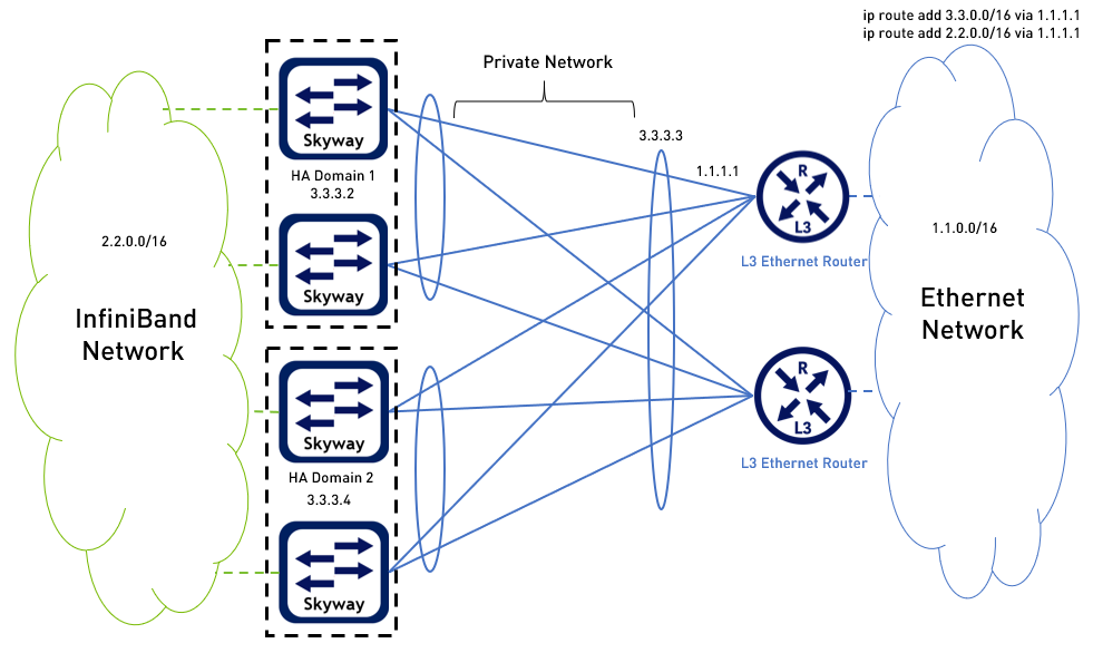
|
Skyway Connectivity to the Ethernet Using L2 Ethernet Switches
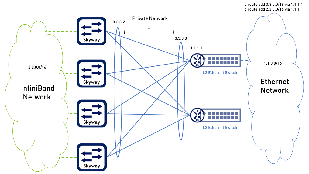
In this above use case, every Skyway-facing port on the side of the L2 Ethernet switches should be configured as a router port. In addition, a private network should be established (in the example above, 3.3.0.0/16) between the router ports mentioned above and the Skyways Ethernet port channel. |