Single Root IO Virtualization (SR-IOV)
Single Root IO Virtualization (SR-IOV) is a technology that allows a physical PCIe device to present itself multiple times through the PCIe bus. This technology enables multiple virtual instances of the device with separate resources. Mellanox adapters are capable of exposing in ConnectX®-3 adapter cards up to 126 virtual instances called Virtual Functions (VFs) and ConnectX-4/Connect-IB adapter cards up to 62 virtual instances. These virtual functions can then be provisioned separately. Each VF can be seen as an additional device connected to the Physical Function. It shares the same resources with the Physical Function, and its number of ports equals those of the Physical Function.
SR-IOV is commonly used in conjunction with an SR-IOV enabled hypervisor to provide virtual machines direct hardware access to network resources hence increasing its performance.
In this chapter we will demonstrate setup and configuration of SR-IOV in a Red Hat Linux environment using Mellanox ConnectX® VPI adapter cards family.
To set up an SR-IOV environment, the following is required:
MLNX_OFED Driver
A server/blade with an SR-IOV-capable motherboard BIOS
Hypervisor that supports SR-IOV such as: Red Hat Enterprise Linux Server Version 6.
Mellanox ConnectX® VPI Adapter Card family with SR-IOV capability
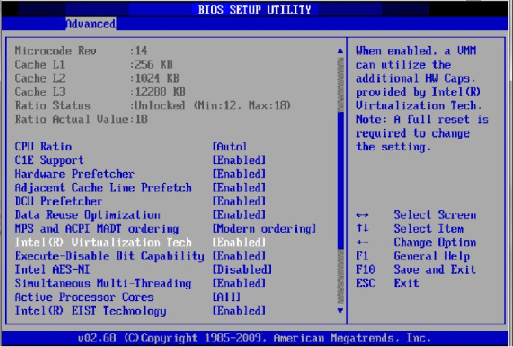
Depending on your system, perform the steps below to set up your BIOS. The figures used in this section are for illustration purposes only. For further information, please refer to the appropriate BIOS User Manual:
Enable "SR-IOV" in the system BIOS.
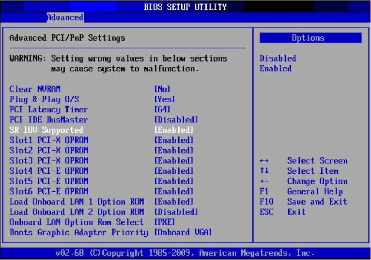
Enable "Intel Virtualization Technology".
Install a hypervisor that supports SR-IOV.
Depending on your system, update the /boot/grub/grub.conf file to include a similar command line load parameter for the Linux kernel.
For example, to Intel systems, add:default=0timeout=5splashimage=(hd0,0)/grub/splash.xpm.gz hiddenmenu title Red Hat Enterprise Linux Server (2.6.32-36.x86-645) root (hd0,0) kernel /vmlinuz-2.6.32-36.x86-64ro root=/dev/VolGroup00/LogVol00 rhgb quiet intel_iommu=on initrd /initrd-2.6.32-36.x86-64.imgNote: Please make sure the parameter "intel_iommu=on" exists when updating the /boot/grub/grub.conf file, otherwise SR-IOV cannot be loaded.
Some OSs use /boot/grub2/grub.cfg file. If your server uses such file, please edit this file instead (add “intel_iommu=on” for the relevant menu entry at the end of the line that starts with "linux16").
Configuring SR-IOV for ConnectX-3/ConnectX-3 Pro
Install the MLNX_OFED driver for Linux that supports SR-IOV.
SR-IOV can be enabled and managed by running the mlxconfig tool and setting the SRIOV_EN parameter to "1" without re-burning the firmware.
To find the mst device run: "mst start" and "mst status"mlxconfig -d <mst_device> s SRIOV_EN=
1For further information, please refer to section "mlxconfig-ChangingDeviceConfigurationTool" in the MFT User Manual (refer to the Firmware Tools (MFT) product page).
Verify the HCA is configured to support SR-IOV.
# mstflint -dev <PCI Device> dc
Verify in the [HCA] section the following fields appear:
[HCA] num_pfs =
1total_vfs = <0-126> sriov_en =truewhere:
Parameter
Recommended Value
num_pfs
1
Note: This field is optional and might not always appear.total_vfs
When using firmware version 2.31.5000 and above, the recommended value is 126.
When using firmware version 2.30.8000 and below, the recommended value is 63
Note: Before setting number of VFs in SR-IOV, please make sure your system can support that amount of VFs. Setting number of VFs larger than what your Hardware and Software can support may cause your system to cease working.
sriov_en
true
Notes:
- If SR-IOV is supported, to enable SR-IOV (if it is not enabled), it is sufficient to set “sriov_en = true” in the INI.
- If the HCA does not support SR-IOV, please contact enterprisesupport@nvidia.comAdd the above fields to the INI if they are missing.
Set the total_vfs parameter to the desired number if you need to change the number of total VFs.
Reburn the firmware using the mlxburn tool if the fields above were added to the INI, or the total_vfs parameter was modified.
If the mlxburn is not installed, please downloaded it from the Firmware Tools (MFT) product page.mlxburn -fw ./fw-ConnectX3-rel.mlx -dev /dev/mst/mt4099_pci_cr0 -conf ./MCX341A-XCG_Ax.ini
Create the text file /etc/modprobe.d/mlx4_core.conf if it does not exist.
Insert an "options" line in the /etc/modprobe.d/mlx4_core.conf file to set the number of VFs. The protocol type per port, and the allowed number of virtual functions to be used by the physical function driver (probe_vf).
For example:
options mlx4_core num_vfs=
5port_type_array=1,2probe_vf=1where:
Parameter
Recommended Value
num_vfs
If absent, or zero: no VFs will be available
If its value is a single number in the range of 0-63: The driver will enable the num_vfs VFs on the HCA and this will be applied to all ConnectX® HCAs on the host.
If its a triplet x,y,z (applies only if all ports are configured as Ethernet) the driver creates:
x single port VFs on physical port 1
y single port VFs on physical port 2 (applies only if such a port exist)
z n-port VFs (where n is the number of physical ports on device). This applies to all ConnectX® HCAs on the host
If it is a format is a string: The string specifies the num_vfs parameter separately per installed HCA.
The string format is: "bb:dd.f-v,bb:dd.f-v,…"bb:dd.f = bus:device.function of the PF of the HCA
v = number of VFs to enable for that HCA which is either a single value or a triplet, as described above.
For example:
num_vfs=5 - The driver will enable 5 VFs on the HCA and this will be applied to all ConnectX® HCAs on the host
num_vfs=00:04.0-5,00:07.0-8 - The driver will enable 5 VFs on the HCA positioned in BDF 00:04.0 and 8 on the one in 00:07.0)
num_vfs=1,2,3 - The driver will enable 1 VF on physical port 1, 2 VFs on physical port 2 and 3 dual port VFs (applies only to dual port HCA when all ports are Ethernet ports).
num_vfs=00:04.0-5;6;7,00:07.0-8;9;10 - the driver will enable:
HCA positioned in BDF 00:04.0
5 single VFs on port 1
6 single VFs on port 2
7 dual port VFs
HCA positioned in BDF 00:07.0
8 single VFs on port 1
9 single VFs on port 2
10 dual port VFs
Applies when all ports are configure as Ethernet in dual port HCAs
Notes:
PFs not included in the above list will not have SR-IOV enabled.
Triplets and single port VFs are only valid when all ports are configured as Ethernet. When an InfiniBand port exists, only num_vfs=a syntax is valid where "a" is a single value that represents the number of VFs.
The second parameter in a triplet is valid only when there are more than 1 physical port.
In a triplet, x+z<=63 and y+z<=63, the maximum number of VFs on each physical port must be 63.
port_type_array
Specifies the protocol type of the ports. It is either one array of 2 port types 't1,t2' for all devices or list of BDF to port_type_array 'bb:dd.f-t1;t2,...'. (string)
Valid port types: 1-ib, 2-eth, 3-auto, 4-N/A
If only a single port is available, use the N/A port type for port2 (e.g '1,4').
Note that this parameter is valid only when num_vfs is not zero (i.e., SRIOV is enabled). Otherwise, it is ignored.probe_vf
If absent or zero: no VF interfaces will be loaded in the Hypervisor/host
If num_vfs is a number in the range of 1-63, the driver running on the Hypervisor will itself activate that number of VFs. All these VFs will run on the Hypervisor. This number will apply to all ConnectX® HCAs on that host.
If its a triplet x,y,z (applies only if all ports are configured as Ethernet), the driver probes:
x single port VFs on physical port 1
y single port VFs on physical port 2 (applies only if such a port exist)
z n-port VFs (where n is the number of physical ports on device). Those VFs are attached to the hypervisor.
If its format is a string: the string specifies the probe_vf parameter separately per installed HCA.
The string format is: "bb:dd.f-v,bb:dd.f-v,…bb:dd.f = bus:device.function of the PF of the HCA
v = number of VFs to use in the PF driver for that HCA which is either a single value or a triplet, as described above
For example:
probe_vfs=5 - The PF driver will activate 5 VFs on the HCA and this will be applied to all ConnectX® HCAs on the host
probe_vfs=00:04.0-5,00:07.0-8 - The PF driver will acti- vate 5 VFs on the HCA positioned in BDF 00:04.0 and 8 for the one in 00:07.0)
probe_vf=1,2,3 - The PF driver will activate 1 VF on physical port 1, 2 VFs on physical port 2 and 3 dual port VFs (applies only to dual port HCA when all ports are Ethernet ports).
This applies to all ConnectX® HCAs in the host.probe_vf=00:04.0-5;6;7,00:07.0-8;9;10 - The PF driver will activate:
HCA positioned in BDF 00:04.0
5 single VFs on port 1
6 single VFs on port 2
7 dual port VFs
HCA positioned in BDF 00:07.0
8 single VFs on port 1
9 single VFs on port 2
10 dual port VFs
Applies when all ports are configure as Ethernet in dual port HCAs.
Notes:
PFs not included in the above list will not activate any of their VFs in the PF driver
Triplets and single port VFs are only valid when all ports are configured as Ethernet. When an InfiniBand port exist, only probe_vf=a syntax is valid where "a" is a single value that represents the number of VFs
The second parameter in a triplet is valid only when there are more than 1 physical port
Every value (either a value in a triplet or a single value) should be less than or equal to the respective value of num_vfs parameter
The example above loads the driver with 5 VFs (num_vfs). The standard use of a VF is a single VF per a single VM. However, the number of VFs varies upon the working mode requirements.
The protocol types are:
- Port 1 = IB
- Port 2 = Ethernet
- port_type_array=2,2 (Ethernet, Ethernet)
- port_type_array=1,1 (IB, IB)
- port_type_array=1,2 (VPI: IB, Ethernet)
- NO port_type_array module parameter: ports are IBWarningFor single port HCAs the possible values are (1,1) or (2,2).
Reboot the server.
WarningIf the SR-IOV is not supported by the server, the machine might not come out of boot/load.
Load the driver and verify the SR-IOV is supported. Run:
lspci | grep Mellanox
03:00.0InfiniBand: Mellanox Technologies MT26428 [ConnectX VPI PCIe2.05GT/s - IB QDR / 10GigE] (rev b0)03:00.1InfiniBand: Mellanox Technologies MT27500 Family [ConnectX-3Virtual Function] (rev b0)03:00.2InfiniBand: Mellanox Technologies MT27500 Family [ConnectX-3Virtual Function] (rev b0)03:00.3InfiniBand: Mellanox Technologies MT27500 Family [ConnectX-3Virtual Function] (rev b0)03:00.4InfiniBand: Mellanox Technologies MT27500 Family [ConnectX-3Virtual Function] (rev b0)03:00.5InfiniBand: Mellanox Technologies MT27500 Family [ConnectX-3Virtual Function] (rev b0)where:
- “03:00” represents the Physical Function
- “03:00.X” represents the Virtual Function connected to the Physical Function
Configuring SR-IOV for ConnectX-4/ConnectX-5/ConnectX-6
(Ethernet)
To set SR-IOV in Ethernet mode, refer to HowTo Configure SR-IOV for ConnectX-4/ConnectX-5/ConnectX-6 with KVM (Ethernet) Community Post.
Configuring SR-IOV for ConnectX-4/Connect-IB/ConnectX-5 (InfiniBand)
Install the MLNX_OFED driver for Linux that supports SR-IOV.
Check if SR-IOV is enabled in the firmware.
mlxconfig -d /dev/mst/mt4113_pciconf0 q Device #
1: ---------- Device type: Connect4 PCI device: /dev/mst/mt4115_pciconf0 Configurations: Current SRIOV_EN1NUM_OF_VFS8FPP_EN1WarningFPP_EN=1 is relevant only for Connect-IB and will fail in ConnectX-4.
If needed, use mlxconfig to set the relevant fields:
mlxconfig -d /dev/mst/mt4113_pciconf0 set SRIOV_EN=1 NUM_OF_VFS=16 FPP_EN=1WarningThe supported number of VFs is 95 per PF.
Reboot the server.
Write to the sysfs file the number of Virtual Functions you need to create for the PF. You can use one of the following equivalent files:
You can use one of the following equivalent files:
- A standard Linux kernel generated file that is available in the new kernels.echo [num_vfs] > /sys/
class/infiniband/mlx5_0/device/sriov_numvfsNote: This file will be generated only if IOMMU is set in the grub.conf file (by adding intel_iommu=on, as seen in the fourth step under “Setting Up SR-IOV”).
- A file generated by the mlx5_core driver with the same functionality as the kernel generated one.echo [num_vfs] > /sys/
class/infiniband/mlx5_0/device/mlx5_num_vfsNote: This file is used by old kernels that do not support the standard file. In such kernels, using sriov_numvfs results in the following error: “bash: echo: write error: Function not implemented”.
The following rules apply when writing to these files:
- If there are no VFs assigned, the number of VFs can be changed to any valid value (0 - max #VFs as set during FW burning)- If there are VFs assigned to a VM, it is not possible to change the number of VFs
- If the administrator unloads the driver on the PF while there are no VFs assigned, the driver will unload and SRI-OV will be disabled
- If there are VFs assigned while the driver of the PF is unloaded, SR-IOV will not be disabled. This means that VFs will be visible on the VM. However, they will not be operational. This is applicable to OSs with kernels that use pci_stub and not vfio.
- The VF driver will discover this situation and will close its resources
- When the driver on the PF is reloaded, the VF becomes operational. The administrator of the VF will need to restart the driver in order to resume working with the VF.Load the driver. To verify that the VFs were created. Run:
lspci | grep Mellanox
08:00.0Infiniband controller: Mellanox Technologies MT27700 Family [ConnectX-4]08:00.1Infiniband controller: Mellanox Technologies MT27700 Family [ConnectX-4]08:00.2Infiniband controller: Mellanox Technologies MT27700 Family [ConnectX-4Virtual Function]08:00.3Infiniband controller: Mellanox Technologies MT27700 Family [ConnectX-4Virtual Function]08:00.4Infiniband controller: Mellanox Technologies MT27700 Family [ConnectX-4Virtual Function]08:00.5Infiniband controller: Mellanox Technologies MT27700 Family [ConnectX-4Virtual Function]Configure the VFs.
After VFs are created, 3 sysfs entries per VF are available under /sys/class/infiniband/mlx5_<PF INDEX>/device/sriov (shown below for VFs 0 to 2):+--
0| +-- node | +-- policy | +-- port +--1| +-- node | +-- policy | +-- port +--2+-- node +-- policy +-- portFor each Virtual Function, the following files are available:
- Node - Node’s GUID:
The user can set the node GUID by writing to the /sys/class/infiniband/<PF>/device/sriov/<index>/node file. The example below, shows how to set the node GUID for VF 0 of mlx5_0.echo
00:11:22:33:44:55:1:0> /sys/class/infiniband/mlx5_0/device/sriov/0/node- Port - Port’s GUID:
The user can set the port GUID by writing to the /sys/class/infiniband/<PF>/device/sriov/<index>/port file. The example below, shows how to set the port GIUID for VF 0 of mlx5_0.echo
00:11:22:33:44:55:2:0> /sys/class/infiniband/mlx5_0/device/sriov/0/port- Policy - The vport's policy. The user can set the port GUID by writing to the /sys/class/infiniband/<PF>/device/sriov/<index>/port file. The policy can be one of:
- Down - the VPort PortState remains 'Down'
- Up - if the current VPort PortState is 'Down', it is modified to 'Initialize'. In all other states, it is unmodified. The result is that the SM may bring the VPort up.
- Follow - follows the PortState of the physical port. If the PortState of the physical port is 'Active', then the VPort implements the 'Up' policy. Otherwise, the VPort PortState is 'Down'.Notes:
- The policy of all the vports is initialized to “Down” after the PF driver is restarted except for VPort0 for which the policy is modified to 'Follow' by the PF driver.
- To see the VFs configuration, you must unbind and bind them or reboot the VMs if the VFs were assigned.Make sure that OpenSM supports Virtualization (Virtualization must be enabled).
The /etc/opensm/opensm.conf file should contain the following line:virt_enabled
2Note: OpenSM and any other utility that uses SMP MADs (ibnetdiscover, sminfo, iblink- info, smpdump, ibqueryerr, ibdiagnet and smpquery) should run on the PF and not on the VFs. In case of multi PFs (multi-host), OpenSM should run on Host0.
VFs Initialization Note
Since the same mlx5_core driver supports both Physical and Virtual Functions, once the Virtual Functions are created, the driver of the PF will attempt to initialize them so they will be available to the OS owning the PF. If you want to assign a Virtual Function to a VM, you need to make sure the VF is not used by the PF driver. If a VF is used, you should first unbind it before assigning to a VM.
To unbind a device use the following command:
Get the full PCI address of the device.
lspci -D
Example:
0000:09:00.2Unbind the device.
echo
0000:09:00.2> /sys/bus/pci/drivers/mlx5_core/unbindBind the unbound VF.
echo
0000:09:00.2> /sys/bus/pci/drivers/mlx5_core/bind
PCI BDF Mapping of PFs and VFs
PCI addresses are sequential for both of the PF and their VFs. Assuming the card's PCI slot is 05:00 and it has 2 ports, the PFs PCI address will be 05:00.0 and 05:00.1.
Given 3 VFs per PF, the VFs PCI addresses will be:
            05:00.2-4 for VFs 0-2 of PF 0 (mlx5_0)
05:00.5-7 for VFs 0-2 of PF 1 (mlx5_1)
Assigning a Virtual Function to a Virtual Machine
This section describes a mechanism for adding a SR-IOV VF to a Virtual Machine.
Assigning the SR-IOV Virtual Function to the Red Hat KVM VM Server
Run the virt-manager.
Double click on the virtual machine and open its Properties.
Go to Details → Add hardware → PCI host device.
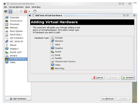
Choose a Mellanox virtual function according to its PCI device (e.g., 00:03.1)
If the Virtual Machine is up reboot it, otherwise start it.
Log into the virtual machine and verify that it recognizes the Mellanox card. Run:
lspci | grep Mellanox
Example:
lspci | grep Mellanox
00:03.0InfiniBand: Mellanox Technologies MT27500 Family [ConnectX-3Virtual Function] (rev b0)[ConnectX-3/ConnectX-3 Pro] Add the device to the /etc/sysconfig/network-scripts/ifcfg-ethX configuration file. The MAC address for every virtual function is configured randomly, therefore it is not necessary to add it.
Ethernet Virtual Function Configuration when Running SR-IOV
SR-IOV Virtual function configuration can be done through Hypervisor iprout2/netlink tool, if present. Otherwise, it can be done via sysfs.
            ip link set { dev DEVICE | group DEVGROUP } [ { up | down } ]
...
[ vf NUM [ mac LLADDR ] [ vlan VLANID [ qos VLAN-QOS ] ]
...
[ spoofchk { on | off} ] ]
...

sysfs configuration (ConnectX-4):

/sys/class/net/enp8s0f0/device/sriov/[VF]

+-- [VF]
| +-- config
| +-- link_state
| +-- mac
| +-- mac_list
| +-- max_tx_rate
| +-- min_tx_rate
| +-- spoofcheck
| +-- stats
| +-- trunk
| +-- trust
| +-- vlan
VLAN Guest Tagging (VGT) and VLAN Switch Tagging (VST)
When running ETH ports on VGT, the ports may be configured to simply pass through packets as is from VFs (VLAN Guest Tagging), or the administrator may configure the Hypervisor to silently force packets to be associated with a VLAN/Qos (VLAN Switch Tagging).
In the latter case, untagged or priority-tagged outgoing packets from the guest will have the VLAN tag inserted, and incoming packets will have the VLAN tag removed.
The default behavior is VGT.
To configure VF VST mode, run:
ip link set dev <PF device> vf <NUM> vlan <vlan_id> [qos <qos>]
where:
NUM = 0..max-vf-num
vlan_id = 0..4095
qos = 0..7
For example:
ip link set dev eth2 vf 2 vlan 10 qos 3 - sets VST mode for VF #2 belonging to PF eth2, with vlan_id = 10 and qos = 3
ip link set dev eth2 vf 2 vlan 0 - sets mode for VF 2 back to VGT
Note: In ConnectX-3 adapter cards family, switching to VGT mode can also be done by setting vlan_id to 4095.
Additional Ethernet VF Configuration Options
Guest MAC configuration - by default, guest MAC addresses are configured to be all zeroes. If the administrator wishes the guest to always start up with the same MAC, he/she should configure guest MACs before the guest driver comes up. The guest MAC may be configured by using:
ip link set dev <PF device> vf <NUM> mac <LLADDR>
For legacy and ConnectX-4 guests, which do not generate random MACs, the administrator should always configure their MAC addresses via IP link, as above.
Spoof checking - Spoof checking is currently available only on upstream kernels newer than 3.1.
ip link set dev <PF device> vf <NUM> spoofchk [on | off]
Guest Link State
ip link set dev <PF device> vf <UM> state [enable| disable| auto]
Virtual Function Statistics
Virtual function statistics can be queried via sysfs:
            cat /sys/class/infiniband/mlx5_2/device/sriov/2/stats tx_packets : 5011
tx_bytes : 4450870
tx_dropped : 0
rx_packets : 5003
rx_bytes : 4450222
rx_broadcast : 0
rx_multicast : 0
tx_broadcast : 0
tx_multicast : 8
rx_dropped : 0
Mapping VFs to Ports
To view the VFs mapping to ports:
Use the ip link tool v2.6.34~3 and above.
ip link
Output:
            61: p1p1: <BROADCAST,MULTICAST> mtu 1500 qdisc noop state DOWN mode DEFAULT group default qlen 1000
    link/ether 00:02:c9:f1:72:e0 brd ff:ff:ff:ff:ff:ff
    vf 0 MAC 00:00:00:00:00:00, vlan 4095, spoof checking off, link-state auto
    vf 37 MAC 00:00:00:00:00:00, vlan 4095, spoof checking off, link-state auto
    vf 38 MAC ff:ff:ff:ff:ff:ff, vlan 65535, spoof checking off, link-state disable
    vf 39 MAC ff:ff:ff:ff:ff:ff, vlan 65535, spoof checking off, link-state disable
When a MAC is ff:ff:ff:ff:ff:ff, the VF is not assigned to the port of the net device it is listed under. In the example above, vf38 is not assigned to the same port as p1p1, in contrast to vf0.
However, even VFs that are not assigned to the net device, could be used to set and change its settings. For example, the following is a valid command to change the spoof check:
ip link set dev p1p1 vf 38 spoofchk on
This command will affect only the vf38. The changes can be seen in ip link on the net device that this device is assigned to.
Mapping VFs to Ports using the mlnx_get_vfs.pl tool
To map the PCI representation in BDF to the respective ports, run:
mlnx_get_vfs.pl
Output:
            BDF 0000:04:00.0
	Port 1:	    2
		        vf0	   0000:04:00.1
		        vf1	   0000:04:00.2
	Port 2:	    2
		        vf2	   0000:04:00.3
		        vf3	   0000:04:00.4
	Both:	    1
		vf4	0000:04:00.5
RoCE Support
RoCE is supported on Virtual Functions and VLANs may be used with it. For RoCE, the hypervisor GID table size is of 16 entries while the VFs share the remaining 112 entries. When the number of VFs is larger than 56 entries, some of them will have GID table with only a single entry which is inadequate if VF's Ethernet device is assigned with an IP address.
When setting num_vfs in mlx4_core module parameter it is important to check that the number of the assigned IP addresses per VF does not exceed the limit for GID table size.
Configuring Pkeys and GUIDs under SR-IOV in ConnectX-3/ConnectX-3 Pro
Port Type Management
Port Type management is static when enabling SR-IOV (the connectx_port_config script will not work). The port type is set on the Host via a module parameter, port_type_array, in mlx- 4_core. This parameter may be used to set the port type uniformly for all installed ConnectX® HCAs, or it may specify an individual configuration for each HCA.
This parameter should be specified as an options line in the file /etc/modprobe.d/mlx- 4_core.conf.
For example, to configure all HCAs to have Port1 as IB and Port2 as ETH, insert the following line:
options mlx4_core port_type_array=1,2
To set HCAs individually, you may use a string of Domain:bus:device.function=x;y
For example, if you have a pair of HCAs, whose PFs are 0000:04:00.0 and 0000:05:00.0, you may specify that the first will have both ports as IB, and the second will have both ports as ETH as follows:
options mlx4_core port_type_array='0000:04:00.0-1;1,0000:05:00.0-2;2
Only the PFs are set via this mechanism. The VFs inherit their port types from their associated PF.
Virtual Function InfiniBand Ports
Each VF presents itself as an independent vHCA to the host, while a single HCA is observable by the network which is unaware of the vHCAs. No changes are required by the InfiniBand sub- system, ULPs, and applications to support SR-IOV, and vHCAs are interoperable with any exist- ing (non-virtualized) IB deployments.
Sharing the same physical port(s) among multiple vHCAs is achieved as follows:
Each vHCA port presents its own virtual GID table
For further details, please refer to Configuring an Alias GUID (under ports/<n>/admin_guids)Each vHCA port presents its own virtual PKey table
The virtual PKey table (presented to a VF) is a mapping of selected indexes of the physical PKey table. The host admin can control which PKey indexes are mapped to which virtual indexes using a sysfs interface. The physical PKey table may contain both full and partial memberships of the same PKey to allow different membership types in different virtual tables.Each vHCA port has its own virtual port state
A vHCA port is up if the following conditions apply:The physical port is up
The virtual GID table contains the GIDs requested by the host admin
The SM has acknowledged the requested GIDs since the last time that the physical port went up
Other port attributes are shared, such as: GID prefix, LID, SM LID, LMC mask
To allow the host admin to control the virtual GID and PKey tables of vHCAs, a new sysfs 'iov sub-tree has been added under the PF InfiniBand device.
If the vHCA comes up without a GUID, make sure you are running the latest version of SM/OpenSM. The SM on QDR switches do not support SR-IOV.
SR-IOV sysfs Administration Interfaces on the Hypervisor
Administration of GUIDs and PKeys is done via the sysfs interface in the Hypervisor (Dom0). This interface is under:
/sys/class/infiniband/<infiniband device>/iov
Under this directory, the following subdirectories can be found:
ports - The actual (physical) port resource tables
Port GID tables:ports/<n>/gids/<n> where 0 <= n <= 127 (the physical port gids)
ports/<n>/admin_guids/<n> where 0 <= n <= 127 (allows examining or changing the administrative state of a given GUID>
ports/<n>/pkeys/<n> where 0 <= n <= 126 (displays the contents of the physical pkey table)
<pci id> directories - one for Dom0 and one per guest. Here, you may see the map- ping between virtual and physical pkey indices, and the virtual to physical gid 0.
Currently, the GID mapping cannot be modified, but the pkey virtual to physical mapping can.
These directories have the structure:<pci_id>/port/<m>/gid_idx/0 where m = 1..2 (this is read-only)
and<pci_id>/port/<m>/pkey_idx/<n>, where m = 1..2 and n = 0..126
For instructions on configuring pkey_idx, please see below.
Configuring an Alias GUID (under ports//admin_guids)
Determine the GUID index of the PCI Virtual Function that you want to pass through to a guest.
For example, if you want to pass through PCI function 02:00.3 to a certain guest, you initially need to see which GUID index is used for this function.
To do so:cat /sys/
class/infiniband/mlx4_0/iov/0000:02:00.3/port/<port_num>/gid_idx/0The value returned will present which guid index to modify on Dom0.
Modify the physical GUID table via the admin_guids sysfs interface.
To configure the GUID at index <n> on port <port_num>:echo NEWGUID > /sys/
class/infiniband/mlx4_0/iov/ports/<port_num>/admin_guids/<guid_in- dex>Example:
echo
"0x002fffff8118"> /sys/class/infiniband/mlx4_0/iov/ports/1/admin_guids/3Note:
/sys/class/infiniband/mlx4_0/iov/ports/<port_num>/admin_guids/0 is read only and cannot be changed.Read the administrative status of the GUID index.
To read the administrative status of GUID index <guid_index> on port number <port_- num>::cat /sys/
class/infiniband/mlx4_0/iov/ports/<port_num>/admin_guids/<guid_index>Check the operational state of a GUID.
/sys/
class/infiniband/mlx4_0/iov/ports/<port_num>/gids (where port_num =1or2)The values indicate what gids are actually configured on the firmware/hardware, and all the entries are R/O.
Compare the value you read under the "admin_guids" directory at that index with the value under the "gids" directory, to verify the change requested in Step 3 has been accepted by the SM, and programmed into the hardware port GID table.
If the value under admin_guids/<m> is different that the value under gids/<m>, the request is still in progress.
Alias GUID Support in InfiniBand
Admin VF GUIDs
As of MLNX_OFED v3.0, the query_gid verb (e.g. ib_query_gid()) returns the admin desired value instead of the value that was approved by the SM to prevent a case where the SM is unreachable or a response is delayed, or if the VF is probed into a VM before their GUID is registered with the SM. If one of the above scenarios occurs, the VF sees an incorrect GID (i.e., not the GID that was intended by the admin).
Despite the new behavior, if the SM does not approve the GID, the VF sees its link as down.
On Demand GUIDs
GIDs are requested from the SM on demand, when needed by the VF (e.g. become active), and are released when the GIDs are no longer in use.
Since a GID is assigned to a VF on the destination HCA, while the VF on the source HCA is shut down (but not administratively released), using GIDs on demand eases the GID migrations.
For compatibility reasons, an explicit admin request to set/change a GUID entry is done immediately, regardless of whether the VF is active or not to allow administrators to change the GUID without the need to unbind/bind the VF.
Alias GUIDs Default Mode
Due to the change in the Alias GUID support in InfiniBand behavior, its default mode is now set as HOST assigned instead of SM assigned. To enable out-of-the-box experience, the PF generates random GUIDs as the initial admin values instead of asking the SM.
Initial GUIDs' Values
Initial GUIDs' values depend on the mlx4_ib module parameter 'sm_guid_assign' as follows:
Mode Type | Description |
admin assigned | Each admin_guid entry has the random generated GUID value. |
sm assigned | Each admin_guid entry for non-active VFs has a value of 0. Meaning, asking a GUID from the SM upon VF activation. When a VF is active, the returned value from the SM becomes the admin value to be asked later again. |
When a VF becomes active, and its admin value is approved, the operational GID entry is changed accordingly. In both modes, the administrator can set/delete the value by using the sysfs Administration Interfaces on the Hypervisor as described above.
Single GUID per VF
Each VF has a single GUID entry in the table based on the VF number. (e.g. VF 1 expects to use GID entry 1). To determine the GUID index of the PCI Virtual Function to pass to a guest, use the sysfs mechanism <gid_idx> directory as described above.
Persistency Support
Once admin request is rejected by the SM, a retry mechanism is set. Retry time is set to 1 second, and for each retry it is multiplied by 2 until reaching the maximum value of 60 seconds. Additionally, when looking for the next record to be updated, the record having the lowest time to be executed is chosen.
Any value reset via the admin_guid interface is immediately executed and it resets the entry's timer.
Partitioning IPoIB Communication using PKeys
PKeys are used to partition IPoIB communication between the Virtual Machines and the Dom0 by mapping a non-default full-membership PKey to virtual index 0, and mapping the default PKey to a virtual pkey index other than zero.
The below describes how to set up two hosts, each with 2 Virtual Machines. Host-1/vm-1 will be able to communicate via IPoIB only with Host2/vm1,and Host1/vm2 only with Host2/vm2.
In addition, Host1/Dom0 will be able to communicate only with Host2/Dom0 over ib0. vm1 and vm2 will not be able to communicate with each other, nor with Dom0.
This is done by configuring the virtual-to-physical PKey mappings for all the VMs, such that at virtual PKey index 0, both vm-1s will have the same pkey and both vm-2s will have the same
PKey (different from the vm-1's), and the Dom0's will have the default pkey (different from the vm's pkeys at index 0).
OpenSM must be used to configure the physical Pkey tables on both hosts.
The physical Pkey table on both hosts (Dom0) will be configured by OpenSM to be:
index
0=0xffffindex1=0xb000index2=0xb030The vm1's virt-to-physical PKey mapping will be:
pkey_idx
0=1pkey_idx1=0The vm2's virt-to-phys pkey mapping will be:
pkey_idx
0=2pkey_idx1=0So that the default pkey will reside on the vms at index 1 instead of at index 0.
The IPoIB QPs are created to use the PKey at index 0. As a result, the Dom0, vm1 and vm2 IPoIB QPs will all use different PKeys.
To partition IPoIB communication using PKeys:
Create a file "/etc/opensm/partitions.conf" on the host on which OpenSM runs, containing lines.
Default=
0x7fff,ipoib : ALL=full ; Pkey1=0x3000,ipoib : ALL=full; Pkey3=0x3030,ipoib : ALL=full;This will cause OpenSM to configure the physical Port Pkey tables on all physical ports on the network as follows:
pkey idx | pkey value --------- |---------
0|0xFFFF1|0xB0002|0xB030The most significant bit indicates if a PKey is a full PKey.
WarningThe ",ipoib" causes OpenSM to pre-create IPoIB the broadcast group for the indicated PKeys.
Configure (on Dom0) the virtual-to-physical PKey mappings for the VMs.
Check the PCI ID for the Physical Function and the Virtual Functions.
lspci | grep Mel
Assuming that on Host1, the physical function displayed by lspci is "0000:02:00.0", and that on Host2 it is "0000:03:00.0"
On Host1 do the following.cd /sys/
class/infiniband/mlx4_0/iov0000:02:00.00000:02:00.10000:02:00.2...Note: 0000:02:00.0 contains the virtual-to-physical mapping tables for the physical function.
0000:02:00.X contain the virt-to-phys mapping tables for the virtual functions.
Do not touch the Dom0 mapping table (under <nnnn>:<nn>:00.0). Modify only tables under 0000:02:00.1 and/or 0000:02:00.2. We assume that vm1 uses VF 0000:02:00.1 and vm2 uses VF 0000:02:00.2Configure the virtual-to-physical PKey mapping for the VMs.
echo
0>0000:02:00.1/ports/1/pkey_idx/1echo1>0000:02:00.1/ports/1/pkey_idx/0echo0>0000:02:00.2/ports/1/pkey_idx/1echo2>0000:02:00.2/ports/1/pkey_idx/0vm1 pkey index 0 will be mapped to physical pkey-index 1, and vm2 pkey index 0 will be mapped to physical pkey index 2. Both vm1 and vm2 will have their pkey index 1 mapped to the default pkey.
On Host2 do the following.
cd /sys/
class/infiniband/mlx4_0/iov echo0>0000:03:00.1/ports/1/pkey_idx/1echo1>0000:03:00.1/ports/1/pkey_idx/0echo0>0000:03:00.2/ports/1/pkey_idx/1echo2>0000:03:00.2/ports/1/pkey_idx/0Once the VMs are running, you can check the VM's virtualized PKey table by doing (on the vm).
cat /sys/
class/infiniband/mlx4_0/ports/[1,2]/pkeys/[0,1]
Start up the VMs (and bind VFs to them).
Configure IP addresses for ib0 on the host and on the guests.
Running Network Diagnostic Tools on a Virtual Function in ConnectX-3/ConnectX-3 Pro
Until now, in MLNX_OFED, administrators were unable to run network diagnostics from a VF since sending and receiving Subnet Management Packets (SMPs) from a VF was not allowed, for security reasons: SMPs are not restricted by network partitioning and may affect the physical network topology. Moreover, even the SM may be denied access from portions of the network by setting management keys unknown to the SM.
However, it is desirable to grant SMP capability to certain privileged VFs, so certain network management activities may be conducted within virtual machines rather than only on the hypervisor.
Granting SMP Capability to a Virtual Function
To enable SMP capability for a VF, one must enable the Subnet Management Interface (SMI) for that VF. By default, the SMI interface is disabled for VFs. To enable SMI mads for VFs, there are two new sysfs entries per VF per on the Hypervisor (under /sys/class/infiniband/mlx4_X/ iov/<b.d.f>/ports/<1 or 2>. These entries are displayed only for VFs (not for the PF), and only for IB ports (not ETH ports).
The first entry, enable_smi_admin, is used to enable SMI on a VF. By default, the value of this entry is zero (disabled). When set to "1", the SMI will be enabled for the VF on the next rebind or openibd restart on the VM that the VF is bound to. If the VF is currently bound, it must be unbound and then re-bound.
The second sysfs entry, smi_enabled, indicates the current enablement state of the SMI. 0 indicates disabled, and 1 indicates enabled. This entry is read-only.
When a VF is initialized (bound), during the initialization sequence, the driver copies the requested smi_state (enable_smi_admin) for that VF/port to the operational SMI state (smi_enabled) for that VF/port, and operate according to the operational state.
Thus, the sequence of operations on the hypervisor is:
Enable SMI for any VF/port that you wish.
Restart the VM that the VF is bound to (or just run /etc/init.d/openibd restart on that VM)
The SMI will be enabled for the VF/port combinations that you set in step 2 above. You will then be able to run network diagnostics from that VF.
Installing MLNX_OFED with Network Diagnostics on a VM
To install MLNX_OFED on a VF which will be enabled to run the tools, run the following on the VM:
mlnx_en_install
MAC Forwarding DataBase (FDB) Management in ConnectX-3/ConnectX-3 Pro
FDB Status Reporting
FDB also know as Forwarding Information Base (FIB) or the forwarding table, is most commonly used in network bridging, routing, and similar functions to find the proper interface to which the input interface should forward a packet.
In the SR-IOV environment, the Ethernet driver can share the existing 128 MACs (for each port) among the Virtual interfaces (VF) and Physical interfaces (PF) that share the same table as follow:
Each VF gets 2 granted MACs (which are taken from the general pool of the 128 MACs)
Each VF/PF can ask for up to 128 MACs on the policy of first-asks first-served (meaning, except for the 2 granted MACs, the other MACs in the pool are free to be asked)
To check if there are free MACs for its interface (PF or VF), run:
/sys/class/net/<ethX>/ fdb_det.
Example:
            cat /sys/class/net/eth2/fdb_det
device eth2: max: 112, used: 2, free macs: 110
To add a new MAC to the interface:
echo +<MAC> > /sys/class/net/eth<X>/fdb
Once running the command above, the interface (VF/PF) verifies if a free MAC exists. If there is a free MAC, the VF/PF takes it from the global pool and allocates it. If there is no free MAC, an error is returned notifying the user of lack of MACs in the pool.
To delete a MAC from the interface:
echo -<MAC> > /sys/class/net/eth<X>/fdb
If /sys/class/net/eth<X>/fdb does not exist, use the Bridge tool from the ip-route2 package which includes the tool to manage FDB tables as the kernel supports FDB callbacks:
            bridge fdb add 00:01:02:03:04:05 permanent self dev p3p1
bridge fdb del 00:01:02:03:04:05 permanent self dev p3p1
bridge fdb show dev p3p1
If adding a new MAC from the kernel's NDO function fails due to insufficient MACs in
the pool, the following error flow will occur:
If the interface is a PF, it will automatically enter the promiscuous mode
If the interface is a VF, it will try to enter the promiscuous mode and since it does not support it, the action will fail and an error will be printed in the kernel's log
Virtual Guest Tagging (VGT+)
VGT+ is an advanced mode of Virtual Guest Tagging (VGT), in which a VF is allowed to tag its own packets as in VGT, but is still subject to an administrative VLAN trunk policy. The policy determines which VLAN IDs are allowed to be transmitted or received. The policy does not determine the user priority, which is left unchanged.
Packets can be sent in one of the following modes: when the VF is allowed to send/receive untagged and priority tagged traffic and when it is not. No default VLAN is defined for VGT+ port. The send packets are passed to the eSwitch only if they match the set, and the received packets are forwarded to the VF only if they match the set.
In some old OSs, such as SLES11 SP4, any VLAN can be created in the VM, regardless of the VGT+ configuration, but traffic will only pass for the allowed VLANs.
Configuring VGT+ for ConnectX-3/ConnectX-3 Pro
The following are the current VGT+ limitations:
The size of the VLAN set is defined to be up to 10 VLANs including the VLAN 0 that is added for untagged/priority-tagged traffic
This behavior applies to all VF traffic: plain Ethernet, and all RoCE transports
VGT+ allowed VLAN sets may be only extended when the VF is online
An operational VLAN set becomes identical as the administration VLAN set only after a VF reset
VGT+ is available in DMFS mode only
The default operating mode is VGT:
            cat /sys/class/net/eth5/vf0/vlan_set
oper:
admin:
Both states (operational and administrative) are empty.
If you set the vlan_set parameter with more the 10 VLAN IDs, the driver chooses the first 10 VLAN IDs provided and ignores all the rest.
To enable VGT+ mode:
Set the corresponding port/VF (in the example below port eth5 VF0) list of allowed VLANs.
echo
0123456789> /sys/class/net/eth5/vf0/vlan_setWhere 0 specifies if untagged/priority tagged traffic is allowed.
Meaning if the below command is run, you will not be able to send/receive untagged traffic.echo
12345678910> /sys/class/net/eth5/vf0/vlan_setReboot the relevant VM for changes to take effect, or run: /etc/init.d/openibd restart
To disable VGT+ mode:
Set the VLAN.
echo > /sys/
class/net/eth5/vf0/vlan_setReboot the relevant VM for changes to take effect, or run: /etc/init.d/openibd restart
To add a VLAN:
In the example below, the following state exist:
            cat /sys/class/net/eth5/vf0/vlan_set
oper: 0 1 2 3
admin: 0 1 2 3
Make an operational VLAN set identical to the administration VLAN.
echo
23456> /sys/class/net/eth5/vf0/vlan_setThe delta will be added to the operational state immediately (4 5 6):
cat /sys/
class/net/eth5/vf0/vlan_set oper:0123456admin:23456Reset the VF for changes to take effect.
Configuring VGT+for ConnectX-4/ConnectX-5
When working in SR-IOV, the default operating mode is VGT.
To enable VGT+ mode:
Set the corresponding port/VF (in the example below port eth5, VF0) range of allowed VLANs.
echo "<add> <start_vid> <end_vid>" > /sys/class/net/eth5/device/sriov/0/trunk
Examples:
Adding VLAN ID range (4-15) to trunk:
echo add
415> /sys/class/net/eth5/device/sriov/0/trunkAdding a single VLAN ID to trunk:
echo add
1717> /sys/class/net/eth5/device/sriov/0/trunk
Note: When VLAN ID = 0, it indicates that untagged and priority-tagged traffics are allowed
To disable VGT+ mode, make sure to remove all VLANs.
echo rem 0 4095 > /sys/class/net/eth5/device/sriov/0/trunk
To remove selected VLANs.
Remove VLAN ID range (4-15) from trunk:
echo rem
415> /sys/class/net/eth5/device/sriov/0/trunkRemove a single VLAN ID from trunk:
echo rem
1717> /sys/class/net/eth5/device/sriov/0/trunk
Virtualized QoS per VF (Rate Limit per VF) in ConnectX-3/ConnectX-3 Pro
Virtualized QoS per VF, (supported in ConnectX®-3/ConnectX®-3 Pro adapter cards only with firmware v2.33.5100 and above), limits the chosen VFs' throughput rate limitations (Maximum throughput). The granularity of the rate limitation is 1Mbits.
The feature is disabled by default. To enable it, set the "enable_vfs_qos" module parameter to "1" and add it to the "options mlx4_core". When set, and when feature is supported, it will be shown upon PF driver load time (in DEV_CAP in kernel log: GranularQoSRatelimitperVFsupport), when mlx4_core module parameter debug_level is set to 1. For further information, please refer to " mlx4_coreParameters "- debug_level parameter).
When set, and supported by the firmware, running as SR-IOV Master and Ethernet link, the driver also provides information on the number of total available vPort Priority Pair (VPPs) and how many VPPs are allocated per priority. All the available VPPs will be allocated on priority 0.
            mlx4_core 0000:1b:00.0: Port 1 Available VPPs 63
mlx4_core 0000:1b:00.0: Port 1 UP 0 Allocated 63 VPPs
mlx4_core 0000:1b:00.0: Port 1 UP 1 Allocated 0 VPPs
mlx4_core 0000:1b:00.0: Port 1 UP 2 Allocated 0 VPPs
mlx4_core 0000:1b:00.0: Port 1 UP 3 Allocated 0 VPPs
mlx4_core 0000:1b:00.0: Port 1 UP 4 Allocated 0 VPPs
mlx4_core 0000:1b:00.0: Port 1 UP 5 Allocated 0 VPPs
mlx4_core 0000:1b:00.0: Port 1 UP 6 Allocated 0 VPPs
mlx4_core 0000:1b:00.0: Port 1 UP 7 Allocated 0 VPPs
Configuring Rate Limit for VFs
The rate limit configuration will take effect only when the VF is in VST mode configured with priority 0.
Rate limit can be configured using the iproute2/netlink tool.
ip link set dev <PF device> vf <NUM> rate <TXRATE>
where:
NUM = 0...<Num of VF>
<TXRATE> in units of 1Mbit/s
The rate limit for VF can be configured:
While setting it to the VST mode.
ip link set dev <PF device> vf <NUM> vlan <vlan_id> [qos <qos>] rate <TXRATE>
Before the VF enters the VST mode with a supported priority.
In this case, the rate limit value is saved and the rate limit configuration is applied when VF state is changed to VST mode.
To disable rate limit configured for a VF set the VF with rate 0. Once the rate limit is set, you cannot switch to VGT or change VST priority.
To view current rate limit configurations for VFs, use the iproute2 tool.
ip link show dev <PF device>
Example:
            89: eth1: <BROADCAST,MULTICAST> mtu 1500 qdisc noop state DOWN mode DEFAULT qlen 1000
    link/ether f4:52:14:5e:be:20 brd ff:ff:ff:ff:ff:ff
    vf 0 MAC 00:00:00:00:00:00, vlan 2, tx rate 1500 (Mbps), spoof checking off, link-state auto
    vf 1 MAC 00:00:00:00:00:00, vlan 4095, spoof checking off, link-state auto
    vf 2 MAC 00:00:00:00:00:00, vlan 4095, spoof checking off, link-state auto
    vf 3 MAC 00:00:00:00:00:00, vlan 4095, spoof checking off, link-state auto
On some OSs, the iptool may not display the configured rate, or any of the VF information, although the both the VST and the rate limit are set through the netlink command. In order to view the rate limit configured, use sysfs provided by the driver. Its location can be found at:
/sys/class/net/<eth-x>/<vf-i>/tx_rate
SR-IOV Advanced Security Features
SR-IOV MAC Anti-Spoofing
Normally, MAC addresses are unique identifiers assigned to network interfaces, and they are fixed addresses that cannot be changed. MAC address spoofing is a technique for altering the MAC address to serve different purposes. Some of the cases in which a MAC address is altered can be legal, while others can be illegal and abuse security mechanisms or disguises a possible attacker.
The SR-IOV MAC address anti-spoofing feature, also known as MAC Spoof Check provides protection against malicious VM MAC address forging. If the network administrator assigns a MAC address to a VF (through the hypervisor) and enables spoof check on it, this will limit the end user to send traffic only from the assigned MAC address of that VF.
MAC Anti-Spoofing Configuration
MAC anti-spoofing is disabled by default.
In the configuration example below, the VM is located on VF-0 and has the following MAC address: 11:22:33:44:55:66.
There are two ways to enable or disable MAC anti-spoofing:
Use the standard IP link commands - available from Kernel 3.10 and above.
To enable MAC anti-spoofing, run:
ip link set ens785f1 vf
0spoofchk onTo disable MAC anti-spoofing, run:
ip link set ens785f1 vf
0spoofchk off
Specify echo "ON" or "OFF" to the file located under /sys/class/net/<ETH_IF_NAME> / device/sriov/<VF index>/spoofchk.
To enable MAC anti-spoofing, run:
echo
"ON"> /sys/class/net/ens785f1/vf/0/spoofchkTo disable MAC anti-spoofing, run:
echo
"OFF"> /sys/class/net/ens785f1/vf/0/spoofchk
This configuration is non-persistent and does not survive driver restart.
In order for spoof-check enabling/disabling to take effect while the VF is up and running on ConnectX-3 Pro adapter cards, it is required to perform a driver restart on the guest OS.
Limit and Bandwidth Share Per VF
This feature enables rate limiting traffic per VF in SR-IOV mode for ConnectX-4/ConnectX-4 Lx/ConnectX-5 adapter cards. For details on how to configure rate limit per VF for ConnectX-4/ ConnectX-5, refer to HowTo Configure Rate Limit per VF for ConnectX-4/ConnectX-5/ConnectX-6 Community post.
Limit Bandwidth per Group of VFs
VFs Rate Limit for vSwitch (OVS) feature allows users to join available VFs into groups and set a rate limitation on each group. Rate limitation on a VF group ensures that the total Tx bandwidth that the VFs in this group get (altogether combined) will not exceed the given value.
With this feature, a VF can still be configured with an individual rate limit as in the past (under /sys/class/net/<ifname>/device/sriov/<vf_num>/max_tx_rate). However, the actual bandwidth limit on the VF will eventually be determined considering the VF group limitation and how many VFs are in the same group.
For example: 2 VFs (0 and 1) are attached to group 3.
Case 1: The rate limitation on the group is set to 20G. Rate limit of each VF is 15G
Result: Each VF will have a rate limit of 10G
Case 2: Group’s max rate limitation is still set to 20G. VF 0 is configured to 30G limit, while VF 1 is configured to 5G rate limit
Result: VF 0 will have 15G de-facto. VF 1 will have 5G
The rule of thumb is that the group’s bandwidth is distributed evenly between the number of VFs in the group. If there are leftovers, they will be assigned to VFs whose individual rate limit has not been met yet.
VFs Rate Limit Feature Configuration
When VF rate group is supported by FW, the driver will create a new hierarchy in the SRI-OV sysfs named “groups” (/sys/class/net/<ifname>/device/sriov/groups/). It will contain all the info and the configurations allowed for VF groups.
All VFs are placed in group 0 by default since it is the only existing group following the initial driver start. It would be the only group available under /sys/class/net/<ifname>/device/sriov/groups/
The VF can be moved to a different group by writing to the group file -> echo $GROUP_ID > /sys/class/net/<ifname>/device/sriov/<vf_id>/group
The group IDs allowed are 0-255
Only when there is at least 1 VF in a group, there will be a group configuration available under /sys/class/net/<ifname>/device/sriov/groups/ (Except for group 0, which is always available even when it’s empty).
Once the group is created (by moving at least 1 VF to that group), users can configure the group’s rate limit. For example:
echo 10000 > /sys/class/net/<ifname>/device/sriov/5/max_tx_rate – setting individual rate limitation of VF 5 to 10G (Optional)
echo 7 > /sys/class/net/<ifname>/device/sriov/5/group – moving VF 5 to group 7
echo 5000 > /sys/class/net/<ifname>/device/sriov/groups/7/max_tx_rate – setting group 7 with rate limitation of 5G
When running traffic via VF 5 now, it will be limited to 5G because of the group rate limit even though the VF itself is limited to 10G
echo 3 > /sys/class/net/<ifname>/device/sriov/5/group – moving VF 5 to group 3
Group 7 will now disappear from /sys/class/net/<ifname>/device/sriov/groups since there are 0 VFs in it. Group 3 will now appear. Since there’s no rate limit on group 3, VF 5 can transmit at 10G (thanks to its individual configuration)
Notes:
You can see to which group the VF belongs to in the ‘stats’ sysfs (cat /sys/class/net/<ifname>/device/sriov/<vf_num>/stats)
You can see the current rate limit and number of attached VFs to a group in the group’s ‘config’ sysfs (cat /sys/class/net/<ifname>/device/sriov/groups/<group_id>/config)
Bandwidth Guarantee per Group of VFs
Bandwidth guarantee (minimum BW) can be set on a group of VFs to ensure this group is able to transmit at least the amount of bandwidth specified on the wire.
Note the following:
The minimum BW settings on VF groups determine how the groups share the total BW between themselves. It does not impact an individual VF’s rate settings.
The total minimum BW that is set on the VF groups should not exceed the total line rate. Otherwise, results are unexpected.
It is still possible to set minimum BW on the individual VFs inside the group. This will determine how the VFs share the group’s minimum BW between themselves. The total minimum BW of the VF member should not exceed the minimum BW of the group.
For instruction on how to create groups of VFs, see Limit Bandwidth per Group of VFs above.
Example
With a 40Gb link speed, assuming 4 groups and default group 0 have been created:
            echo 20000 > /sys/class/net/<ifname>/device/sriov/group/1/min_tx_rate
echo 5000 > /sys/class/net/<ifname>/device/sriov/group/2/min_tx_rate
echo 15000 > /sys/class/net/<ifname>/device/sriov/group/3/min_tx_rate
            Group 0(default) : 0 - No BW guarantee is configured.
Group 1 : 20000 - This is the maximum min rate among groups
Group 2 : 5000 which is 25% of the maximum min rate
Group 3 : 15000 which is 75% of the maximum min rate
Group 4 : 0 - No BW guarantee is configured.
Assuming there are VFs attempting to transmit in full line rate in all groups, the results would look like: In which case, the minimum BW allocation would be:
            Group0 – Will have no BW to use since no BW guarantee was set on it while other groups do have such settings.
Group1 – Will transmit at 20Gb/s
Group2 – Will transmit at 5Gb/s
Group3 – Will transmit at 15Gb/s
Group4 - Will have no BW to use since no BW guarantee was set on it while other groups do have such settings.
Privileged VFs
In case a malicious driver is running over one of the VFs, and in case that VF's permissions are not restricted, this may open security holes. However, VFs can be marked as trusted and can thus receive an exclusive subset of physical function privileges or permissions. For example, in case of allowing all VFs, rather than specific VFs, to enter a promiscuous mode as a privilege, this will enable malicious users to sniff and monitor the entire physical port for incoming traffic, including traffic targeting other VFs, which is considered a severe security hole.
Privileged VFs Configuration
In the configuration example below, the VM is located on VF-0 and has the following MAC address: 11:22:33:44:55:66.
There are two ways to enable or disable trust:
Use the standard IP link commands - available from Kernel 4.5 and above.
To enable trust for a specific VF, run:
ip link set ens785f1 vf
0trust onTo disable trust for a specific VF, run:
ip link set ens785f1 vf
0trust off
Specify echo "ON" or "OFF" to the file located under /sys/class/net/<ETH_IF_NAME> / device/sriov/<VF index>/trust.
To enable trust for a specific VF, run:
echo
"ON"> /sys/class/net/ens785f1/device/sriov/0/trustTo disable trust for a specific VF, run:
echo
"OFF"> /sys/class/net/ens785f1/device/sriov/0/trust
Probed VFs
Probing Virtual Functions (VFs) after SR-IOV is enabled might consume the adapter cards' resources. Therefore, it is recommended not to enable probing of VFs when no monitoring of the VM is needed.
VF probing can be disabled in two ways, depending on the kernel version installed on your server:
If the kernel version installed is v4.12 or above, it is recommended to use the PCI sysfs interface sriov_drivers_autoprobe. For more information, see linux-nextbranch.
If the kernel version installed is older than v4.12, it is recommended to use the mlx5_core module parameter probe_vf with MLNX_OFED v4.1 or above.
Example:
echo 0 > /sys/module/mlx5_core/parameters/probe_vf
For more information on how to probe VFs, see HowTo Configure and Probe VFs on mlx5 DriversCommunity post.
VF Promiscuous Rx Modes
VF Promiscuous Mode
VFs can enter a promiscuous mode that enables receiving the unmatched traffic and all the multicast traffic that reaches the physical port in addition to the traffic originally targeted to the VF. The unmatched traffic is any traffic's DMAC that does not match any of the VFs' or PFs' MAC addresses.
Note: Only privileged/trusted VFs can enter the VF promiscuous mode.
To set the promiscuous mode on for a VF, run:
ifconfig eth2 promisc
ifconfig eth2 –promisc
VF All-Multi Mode
VFs can enter an all-multi mode that enables receiving all the multicast traffic sent from/to the other functions on the same physical port in addition to the traffic originally targeted to the VF.
Note: Only privileged/trusted VFs can enter the all-multi RX mode.
ifconfig eth2 allmulti
#ifconfig eth2 –allmulti
For Hypervisors, detach all the Virtual Functions (VF) from all the Virtual Machines (VM) or stop the Virtual Machines that use the Virtual Functions.
Please be aware that stopping the driver when there are VMs that use the VFs, will cause machine to hang.Run the script below. Please be aware, uninstalling the driver deletes the entire driver's file, but does not unload the driver.
[root
@swl022~]# /usr/sbin/ofed_uninstall.sh This program will uninstall all OFED packages on your machine. Do you want tocontinue?[y/N]:y Running /usr/sbin/vendor_pre_uninstall.sh Removing OFED Software installations Running /bin/rpm -e --allmatches kernel-ib kernel-ib-devel libibverbs libibverbs-devel libibverbs-devel-staticlibibverbs-utils libmlx4 libmlx4-devel libibcm libibcm-devel libibumad libibumad-devel libibumad-staticlibibmad libibmad-devel libibmad-staticlibrdmacm librdmacm-utils librdmacm-devel ibacm opensm-libs opensm-devel perftest compat-dapl compat-dapl-devel dapl dapl-devel dapl-devel-staticdapl-utils srptools infiniband-diags-guest ofed-scripts opensm-devel warning: /etc/infiniband/openib.conf saved as /etc/infiniband/openib.conf.rpmsave Running /tmp/2818-ofed_vendor_post_uninstall.shRestart the server.