Appendix: Optical Connector and Fiber Cable
The optical port in the parallel 2 x 4-lane optical transceiver is a male MPO connector with alignment pins, mating with fiber-optic cables with female MPO connector.
QSFP28 Optical Receptacle and Lane Assignment (transceiver, front view)
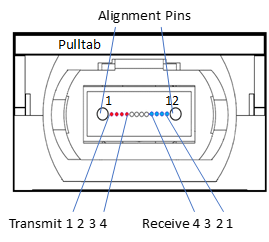
Reference: IEC specification IEC 61754-7.
The fiber which connects transceiver A’s lane 1 must end at transceiver B’s lane 12 at the other end of the link. This calls for a crossed MPO cable, also referred to as ‘Type B’. The fiber is standard OM3 or OM4 multi-mode fiber. The maximum length is found in Optical Specifications.
MPO to MPO Patch Cable Fiber Connections
Connector A MPO/UPC Female | Connection | Connector B MPO/UPC Female |
1 | → | 12 |
2 | → | 11 |
3 | → | 10 |
4 | → | 9 |
5 | Not Connected | 8 |
6 | Not Connected | 7 |
7 | Not Connected | 6 |
8 | Not Connected | 5 |
9 | ← | 4 |
10 | ← | 3 |
11 | ← | 2 |
12 | ← | 1 |
Multiple MPO patch cables can be connected in series, but each added connector pair increases modal dispersion in the link which again impairs performance. An odd number of ‘crosses’ must be used between transceivers at the two ends.
Typical look of the Fiber Cable
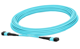
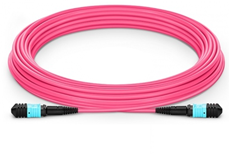
OM3 Multimode Cable OM4 Multimode Cable
Some vendors use aqua color for OM4 cables.