Tool-Less 4-Post Mounting Rail-Kit
Kit Part Number | Kit Legacy Part Number | Rack Size and Rack Depth Range |
930-9NRKT-00JS-000 | MTEF-KIT-M-TL | NVIDIA Tool-less rack installation kit, 4-post rack, for SN2201 switch |
The following parts are included in the tool-less rail kit (see figure below):
2x Rack mount rails (A)
2x Rack mount blades (B)
2x Inner rails (C)
Rail-Kit Parts
2xA 2xB 2xC 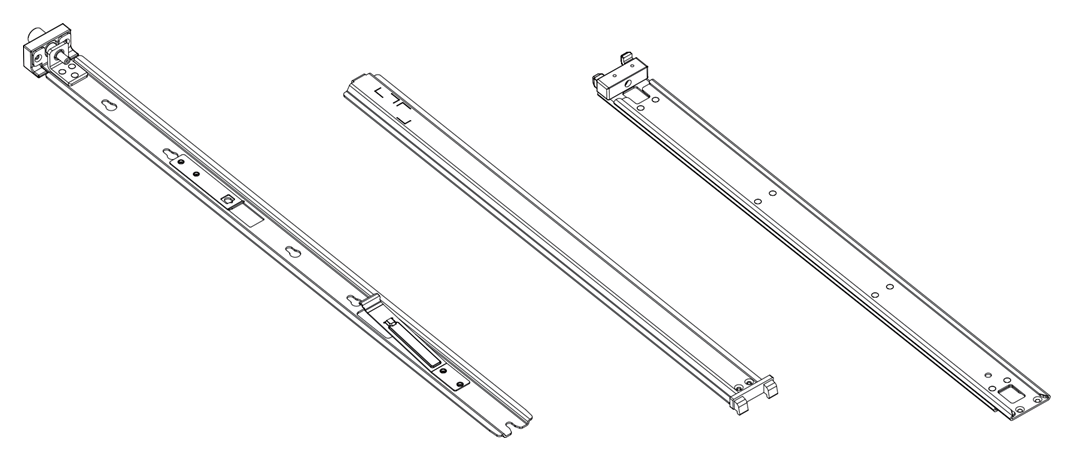
|
Prerequisites:
At least two people are required to safely mount the system in the rack.
All servers and systems in the rack should be planned with the same airflow direction.
All FRU components must have the same airflow direction. A mismatch in the airflow will affect the heat dissipation.
The part of the system to which you choose to attach the rails will determine the system’s adjustable side. The system’s part to which the brackets are attached will be adjacent to the cabinet.
The FRU side is extractable. Mounting the rack brackets inverted to the FRU side will allow you to slide the FRUs, in and out.
Installation
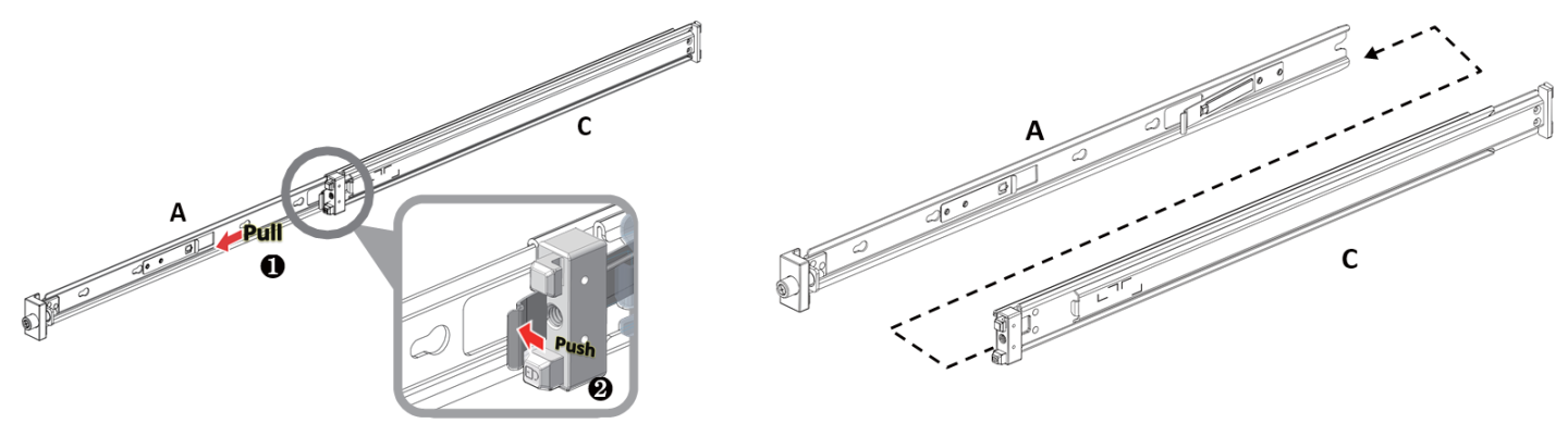
Extract the inner rails (A) from the other rails by pressing the spring latch and pulling it out, as shown in the following illustration:
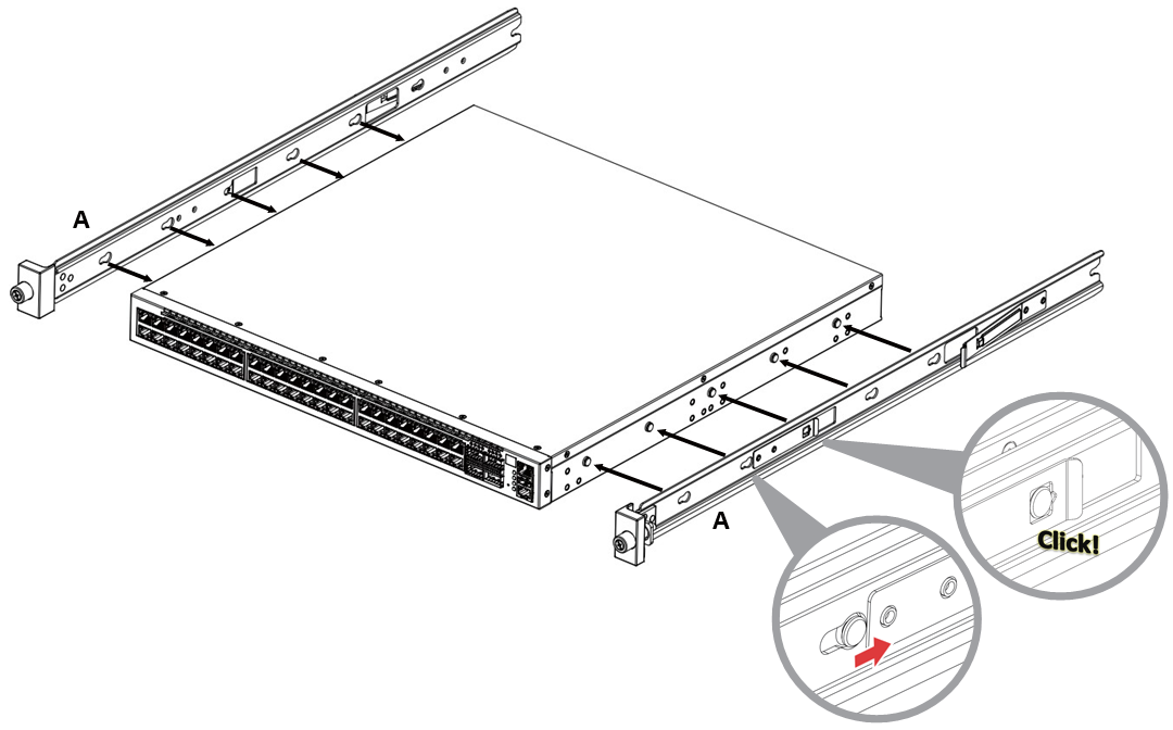
Mount the inner rails (A) onto the chassis:
Attach the switch to the left and right inner rails according to your installation selection -
Standard Installation:
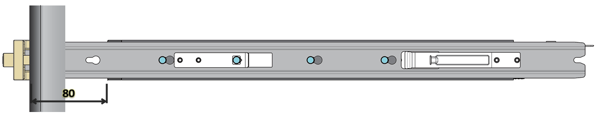
The inner rails should be assembled to the switch using the first five holes (from its front side).
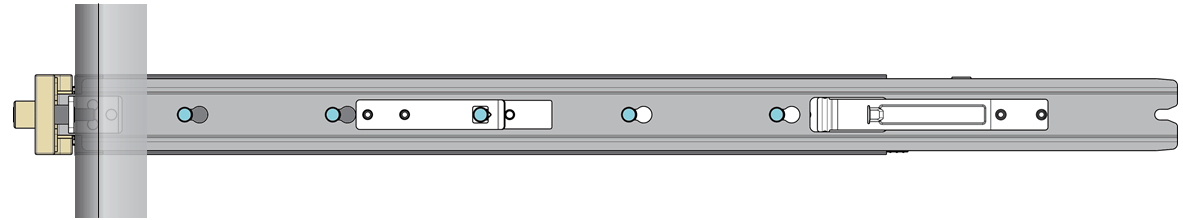
Recessed Installation:
The inner rails should be assembled to the switch skipping the first hole (from its front side).
Secure the assembly by pushing the chassis’ pins through the slider key holes, until a click is heard and locking occurs.
-
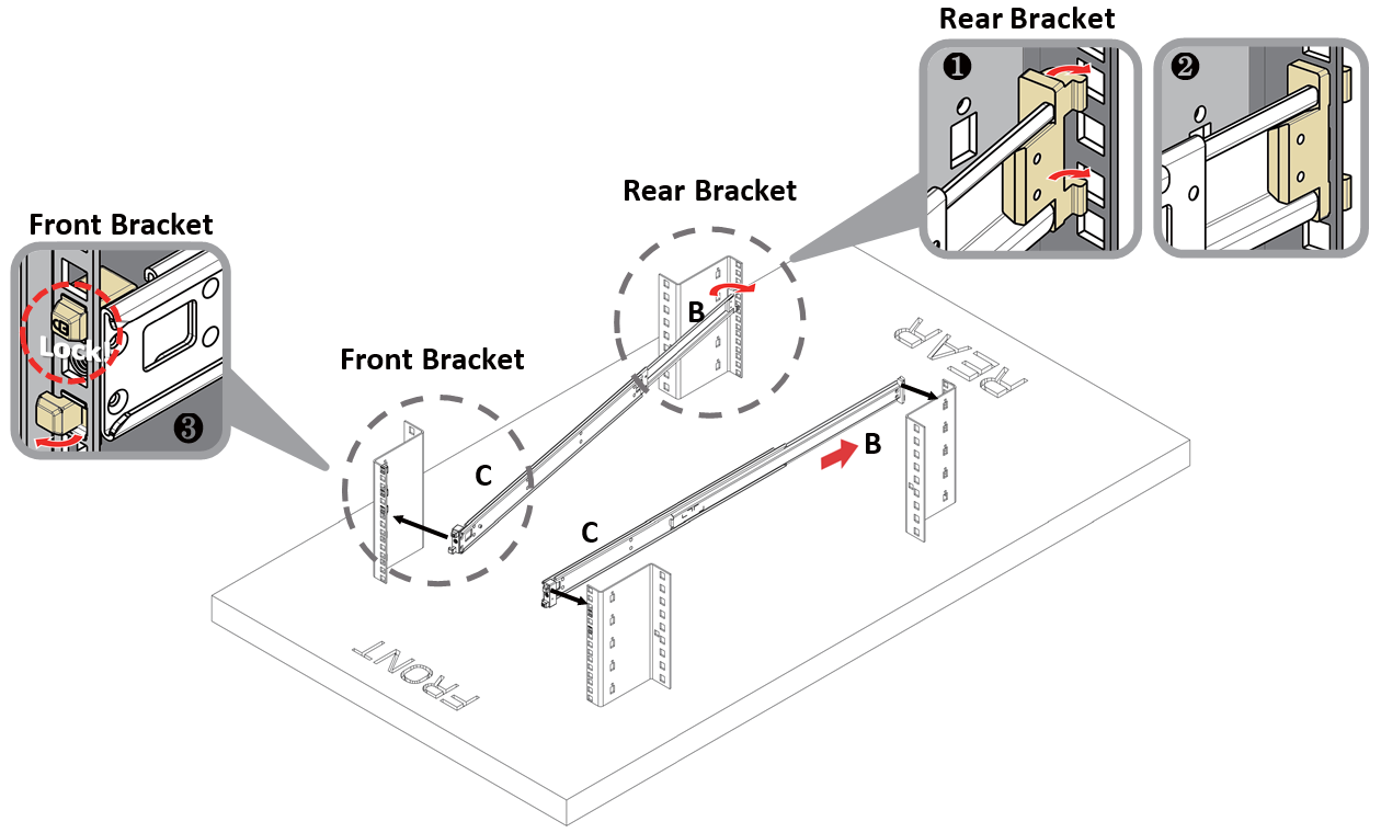
Install the outer rails (B+C) in the rack, as shown in the following illustration:
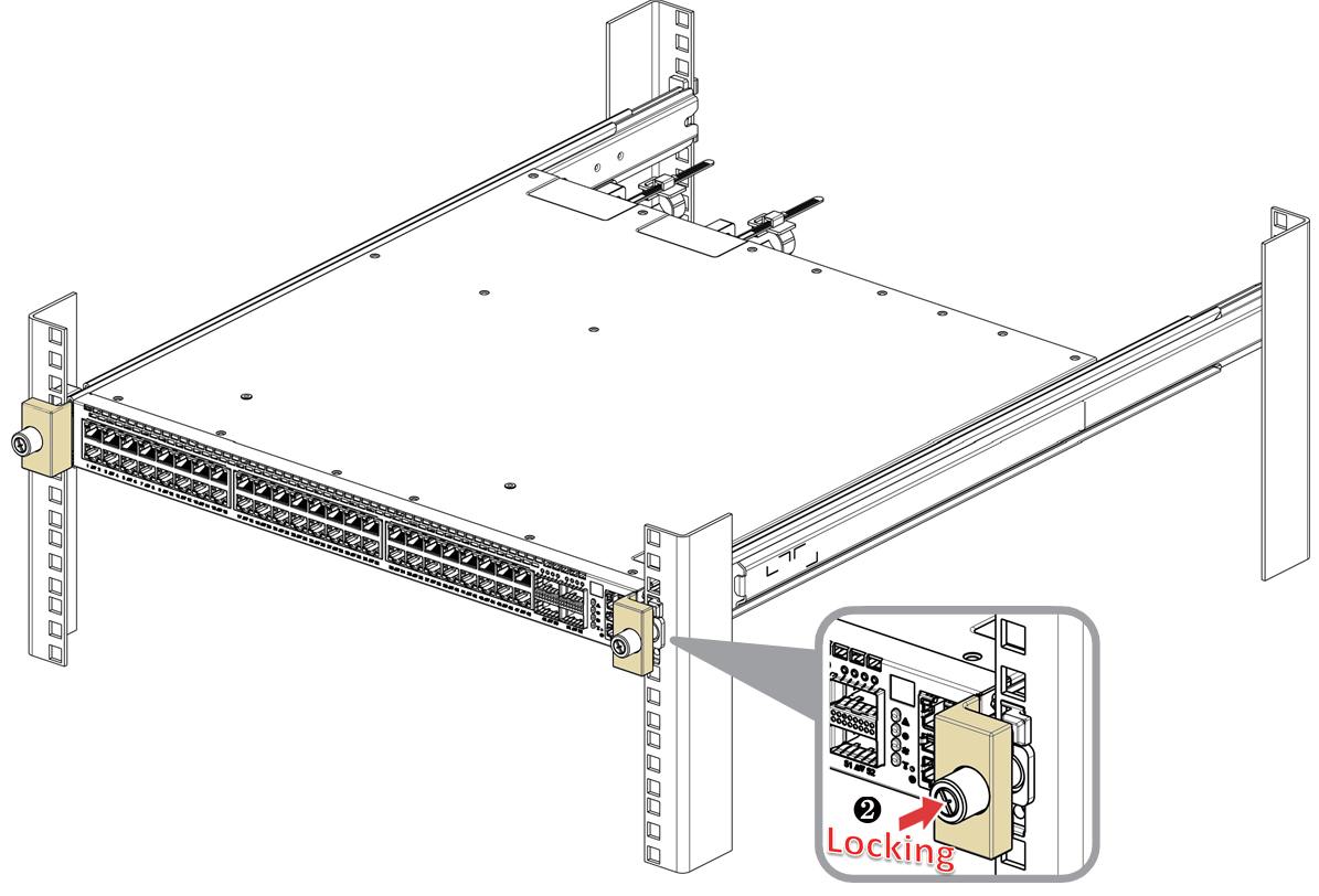
Mount the chassis onto the rack:
Insert the chassis into the middle-outer rails installed in the rack (C).
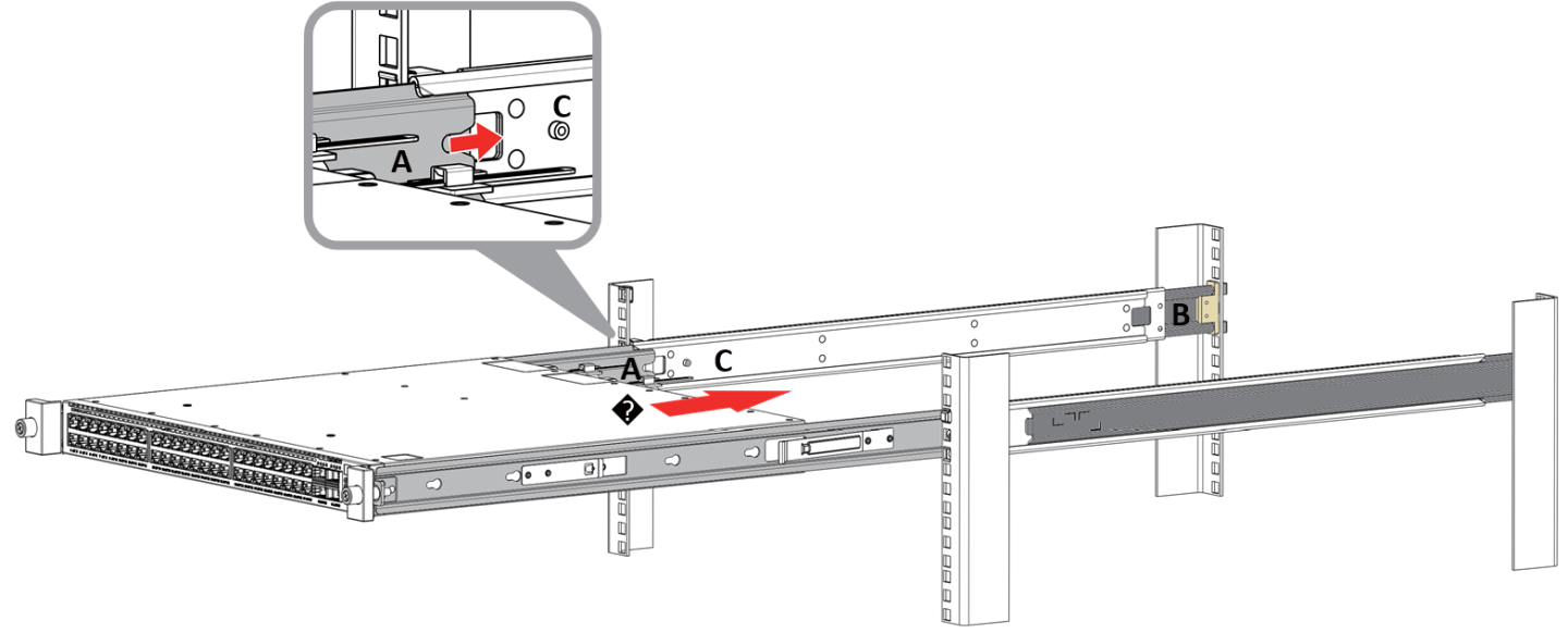
Secure the chassis in place by tightening the thumb-screws.