System Admin
This page is only supported for Admin users
The Summary Report View offers a comprehensive overview of the loaded topology, providing information about the state of devices and their associated agents.
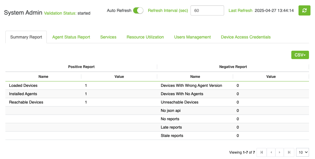
The report includes the following details:
Number of loaded Devices
Number of installed Agents
Number of reachable devices
Number of unreachable devices
Number of Devices with wrong agent version
Number of Devices with no agents
Number of no json api
Number of no reports
Number of late reports
Number of stale reports
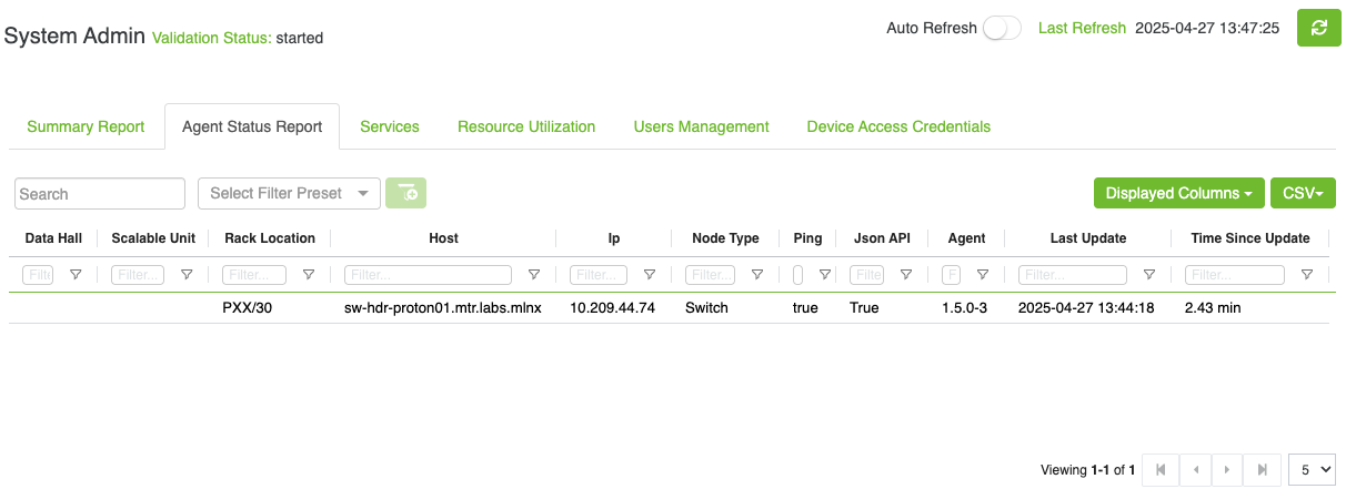
The Agent Status Report delivers detailed information about the agent installed on each node. The report will also include the node location (rack, unit), type, name and IP.
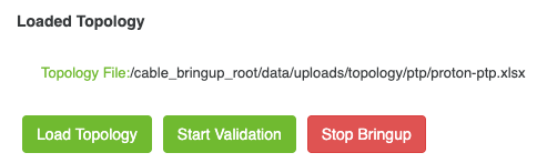
The Service View provides the ability to the user to Load Topology, Start Validation and Stop Bringup.
The Service View enables users to manage the topology by allowing them to load a topology and start/stop validation process.
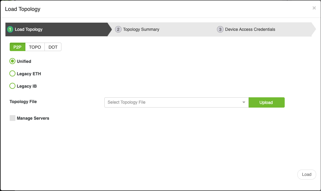
Load Topology
Depending on the fabric type, the Load Topology feature allows users to upload and load a PTP, dot, or topology file. The process involves the following steps:
Accessing the Load Topology Wizard:
Click on the Load Topology button in the UI to open a wizard.
Wizard Steps
The wizard contains 3 steps
Step 1 - Load Topology
In this step, users can choose from three options to load the desired topology file:
P2P: This option uses the load_ptp command to load a P2P file.
Users must provide the following inputs:
Format: PTP file format, which can be one of the following:
Unified: I t accepts various cluster types, including InfiniBand , Ethernet, and NVLink. For more information, please visit Unified Topology Format.
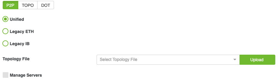
Legace ETH: It accepts only Ethernet fabric. For more information, please visit PTP ETH.
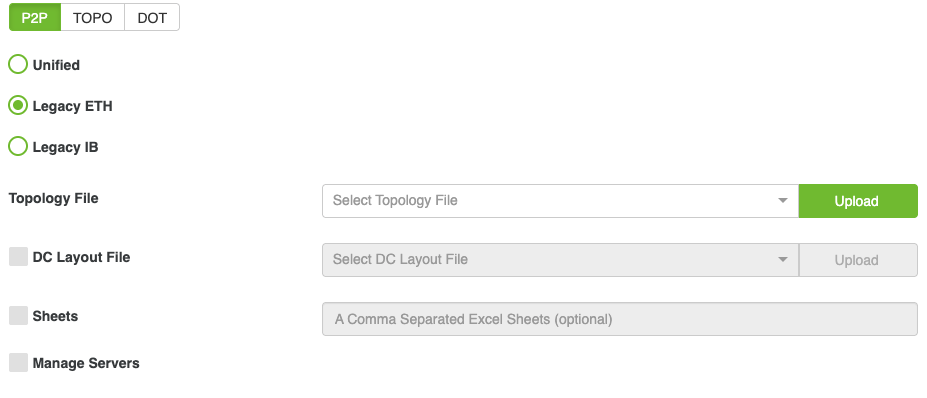
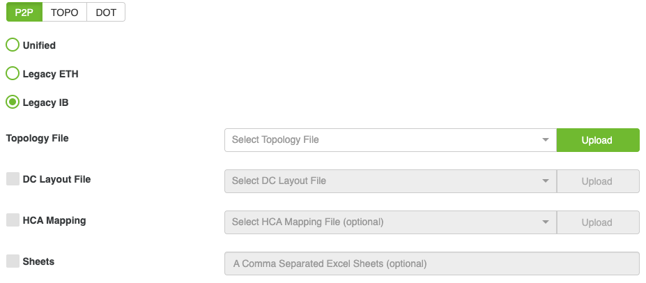
Legacy IB: It accepts only InfiniBand fabric. For more information, please visit PTP IB.
Topology File:
Allows users to select or upload a PTP file.
Files can be chosen from a dropdown menu listing all .xlsx files in the directory: /opt/bringup_data/data/uploads/topology/ptp/
This directory is a shared volume linked to:/cable_bringup_root/data/uploads/topology/ptp/
Users can also upload a file directly from their computer using the Upload button located next to the dropdown menu.
DC Layout File (Optional, Appears Only with Legacy formats):
Used for selecting or uploading a data center floor layout file.
Files can be chosen from a dropdown menu listing all .csv files in the directory: /opt/bringup_data/data/uploads/topology/dc_layout/
This directory is a shared volume linked to: /cable_bringup_root/data/uploads/topology/dc_layout/
Users can upload a file directly from their computer using the Upload button.
Users can enable the DC Layout field by selecting the HCA Mapping checkbox.
HCA Mapping (Optional, Appears Only with Legacy formats):
Allows users to select or upload an HCA mapping file.
Files can be chosen from a dropdown menu listing all .csv files in the directory:/opt/bringup_data/data/uploads/topology/hca_mapping/
This directory is a shared volume linked to:
/cable_bringup_root/data/uploads/topology/hca_mapping/
Users can enable the HCA Mapping field by selecting the HCA Mapping checkbox.
Sheets (Optional, Appears Only with Legacy formats): The user can specify sheets to be included in the file by enabling the Sheets input field (via checkbox) and entering the sheet names as comma-separated values.
Manage Servers: If checked, it manages the servers in the topology file; otherwise, it only manages the switches and ignores the servers.
Topo: This option uses the
load_topocommand to load a topology file.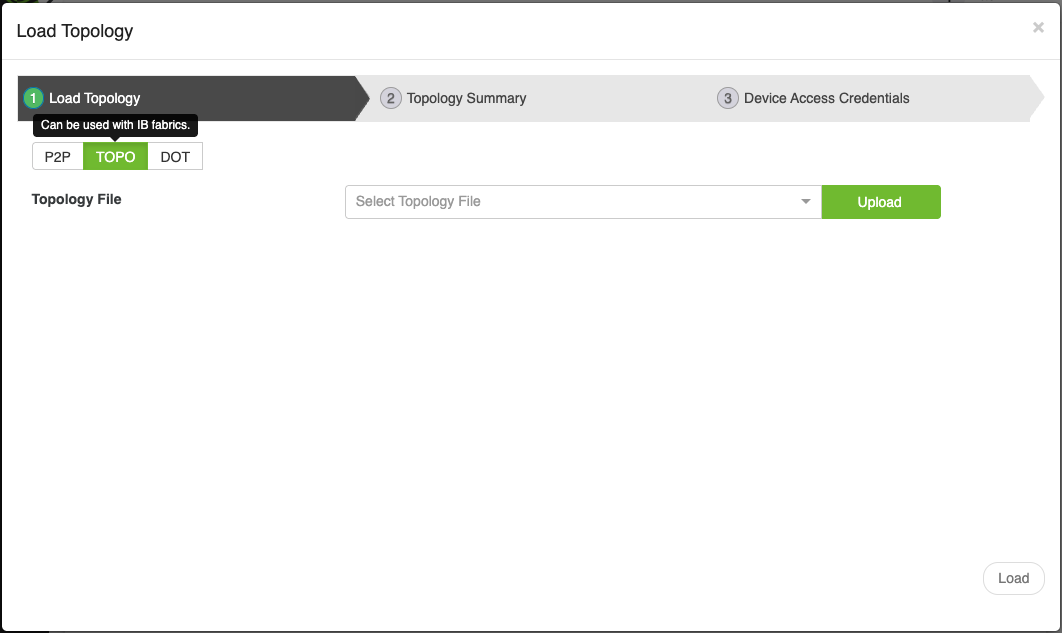
User must provide the following input:
Topology File:
Allows users to select or upload a .topo file.
Files can be chosen from a dropdown menu listing all .topo files in the directory:/opt/bringup_data/data/uploads/topology/topo/
This directory is a shared volume linked to:/cable_bringup_root/data/uploads/topology/topo/
Users can upload a file directly from their computer using the Upload button.
Dot: This option uses the
load_topocommand to load a DOT file.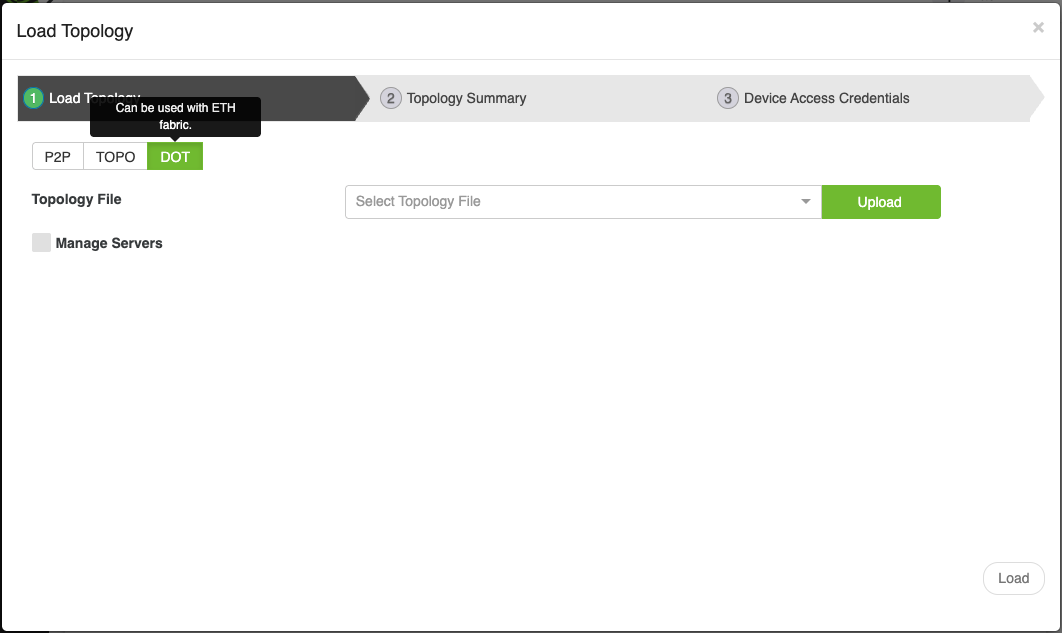
This option uses the
load_topocommand to load a DOT file. User must provide the following inputTopology File:
Allows users to select or upload a .dot file.
Files can be chosen from a dropdown menu listing all .topo files in the directory: /opt/bringup_data/data/uploads/topology/dot/
This directory is a shared volume linked to :/cable_bringup_root/data/uploads/topology/dot/
Users can upload a file directly from their computer using the Upload button.
Manage Servers: If checked, it manages the servers in the topology file; otherwise, it only manages the switches and ignores the servers.
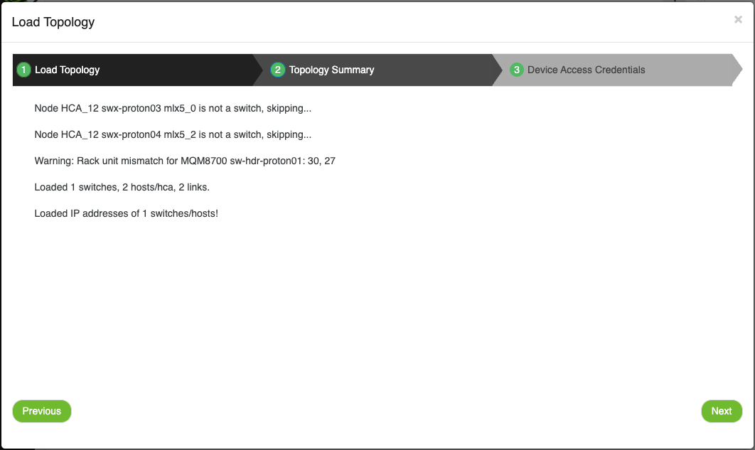
Step 2 - Topology Summary:
After loading the file, this step provides a summary of the loaded topology. Users can review the details to confirm that the correct file and settings have been applied.
Step 3 - Device Access Credentials:
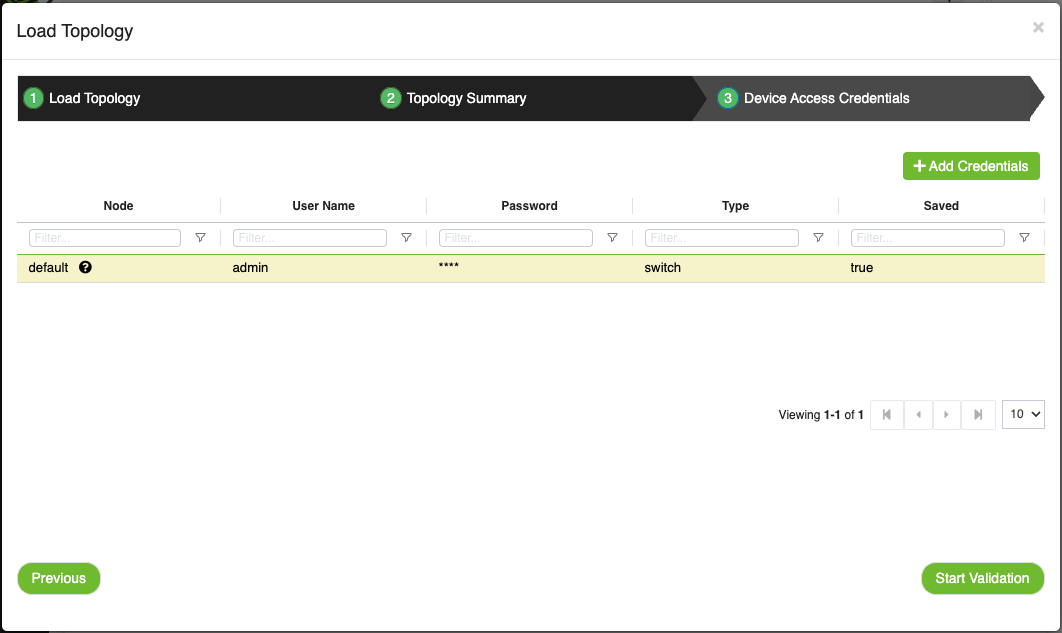
For more information, please visit Device Access Credentials
Proceeding After 'Device Access Credentials':
To continue with validation, users can click the Start Validation button.
Note: If users only want to upload the topology file without starting validation, they can close the wizard by clicking the X button at the top.
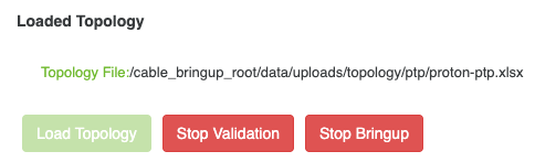
Start Validation
The Start Validation button is used to initiate the validation of the currently loaded topology.
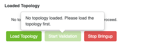
If no topology has been loaded, the Start Validation button will be disabled. Hovering over the button will display a message explaining the requirement to load a topology first.
After loading a topology (as described in the Load Topology section), click the Start Validation if it was not started yet to begin the validation process.
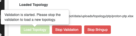
Users can also stop the validation at any time by clicking the Stop Validation button.
While the validation process is running, the Load Topology button is disabled. This restriction ensures that users cannot load a new topology during an ongoing validation process.
Resource utilization is used to track CVT system health and understand how it impacts resource consumption. It will be analyzed across three key areas: storage, memory, and CPU usage.
This analysis will help monitor system performance, optimize resource allocation, and ensure efficient operation.
CPU utilization is calculated over a 3-second interval, meaning it will take 3 seconds for the CPU utilization data to be available.
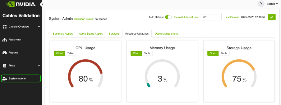
The tab will present resource data in two formats:
Tachometer Chart: A visual gauge that displays the usage percentage for each resource.
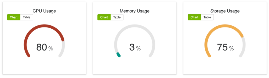
Table: A structured table displaying resource information in detail
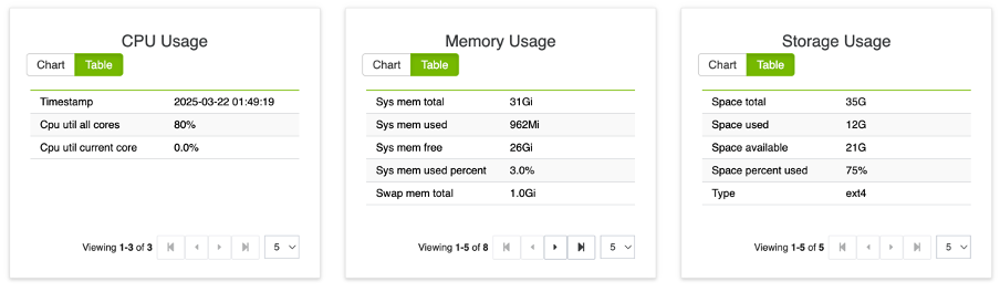
To get the latest data, the user can refresh the view manually by clicking the refresh button or enable automatic refresh.
Tachometer Chart Color Thresholds
The color of the tachometer chart will be determined based on the percentage value of each resource, following these predefined thresholds:
CPU Usage Thresholds
0 - 50% | Normal | 
Blue |
51 - 75% | Warning | 🟠 Orange |
76 - 100% | Critical | 🔴 Red |
Storage Usage Thresholds
0 - 70% | Normal |
Blue |
71 - 90% | Warning | 🟠 Orange |
91 - 100% | Critical | 🔴 Red |
Memory Usage Thresholds
0 - 60% | Normal |
Blue |
61 - 80% | Warning | 🟠 Orange |
81 - 100% | Critical | 🔴 Red |
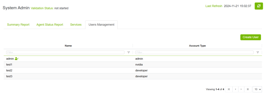
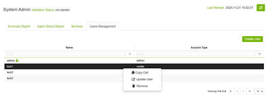
The User Management view allows admin users to manage user accounts within the application. admin can create, update, or delete user accounts as needed.
The tab displays all users in a table, with a special icon indicating the currently logged-in user.
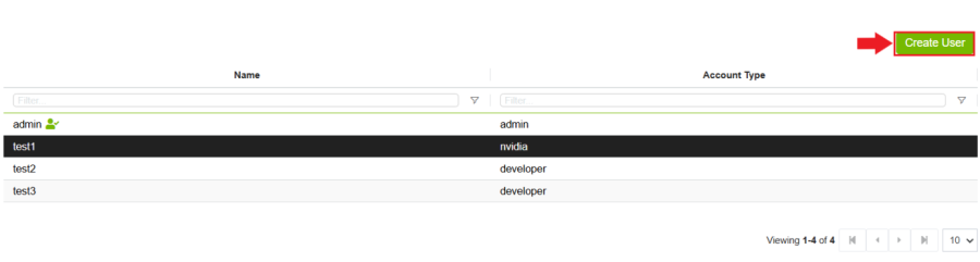
Create Users
Admin can create new user accounts by following these steps:
Accessing the Create User Modal:
Click the Create User button to open a modal for adding a new user.
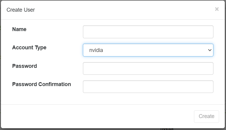
Supported Account Types:
The tool supports the following four account types:
admin: Full access to all features and settings.
nvidia: can access circuits view, rack view and reports only.
cabler: can access circuits view, rack view and reports only.
developer: can access circuits view, rack view and reports only.
Adding User Details:
Fill in the required fields in the modal to create the user account.
Completing the Process:
Click Create to add the new user to the system.
Update user
Admin user can also update the account type or the password or both for any user he wants
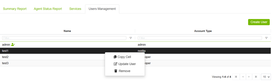
That can be done by right click then click on Update User.
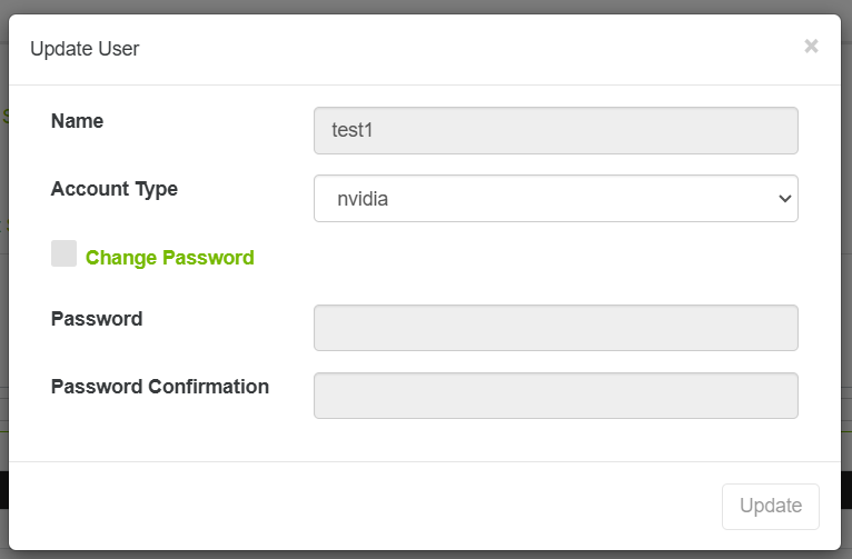
To change the password user, need to check change password checkbox then fill the passwords input.
Delete Use
Admin user can also delete the user by right click then click on Remove User.
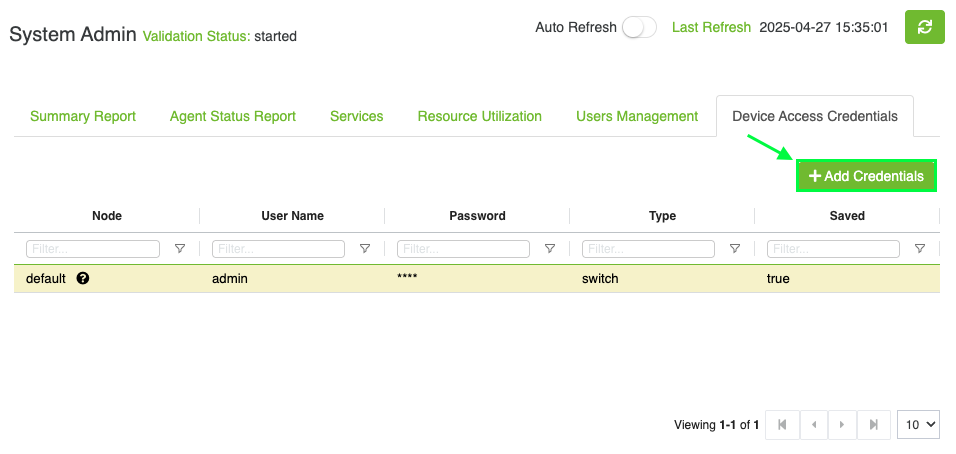
The Device Access Credentials Management component allows you to securely manage credentials (username, password, etc.) for devices in your system.
You can add, view, update, and remove device access credentials through a table and modal interface.
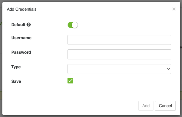
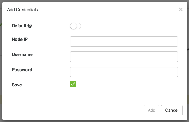
Add Credentials
Admin can add new Credentials by following these steps:
Accessing the Credentials Modal:
Click the 'Add Credentials' button to open a modal for adding a new credential.
2. Fill in the required fields:
Default: Toggle if these are default credentials (applied to all devices without credentials).
Node IP: Enter the device IP (only if not default).
Username: Enter the username for device access.
Password: Enter the password.
Type: Select the device type (only if default).
Save: Check if you want to save these credentials.
Update Existing Credentials
Admin user can also update the existing credentials by right click then clicking on Update Node.
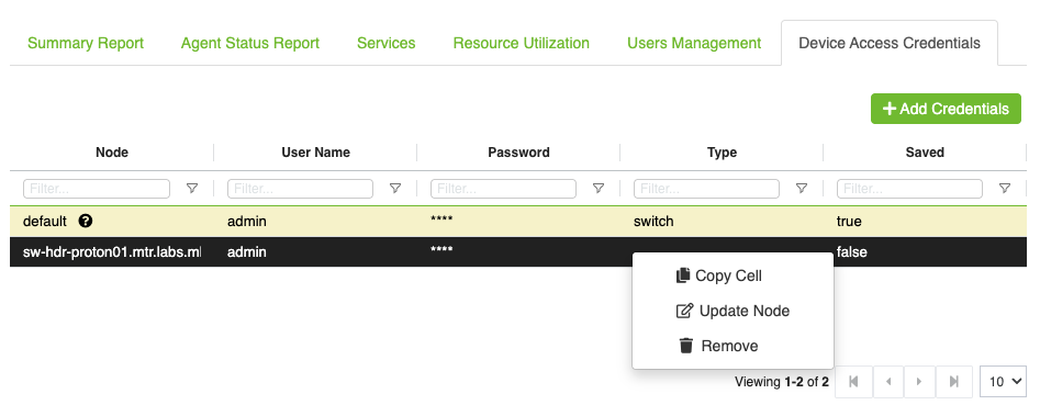
The user can update the username, password, and save status. Updating the password is mandatory when updating the credentials.
Remove Credentials
Admin user can also remove the credentials by right click then click on Remove. only non-default credentials can be removed