Application
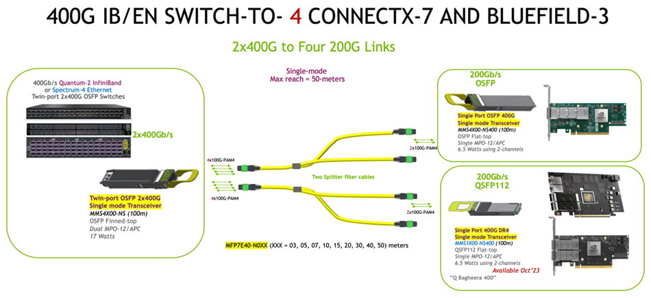
The MFP7E40 Fiber Cable is intended for interconnection of 2 compute or storage servers sharing a port in a high-speed switch in the data center. The cable mates with pluggable optical 400GbE/NDR transceivers such as NVIDIA’s MMX4S00-NS twin-port OSFP DR8 transceiver for InfiniBand and Ethernet systems in the switch end, and MMS4X00-NS400 (OSFP) or MMS1X00-NS400 (QSFP112) in ConnectX-7 network adapters and BlueField-3 DPUs.
Twin port OSFP transceivers must use the same fiber type in both MPO-12/APC ports (straight or 1:2 splitter) and cannot be mixed.
50-meter specification assumes two optical patch panels in the link with total of 4 optical connector junctions
Single-mode fibers use an industry standard yellow fiber jacket color
Jacket is Low-Smoke, Zero-Halogen (LSZH) type to reduce toxic smoke in event of a fire.
The connector has an NVIDIA green connector shell denoting MPO-12/APC. The MPO-12/UPC typically a blue shell for Ultra-flat Polish Connectors.
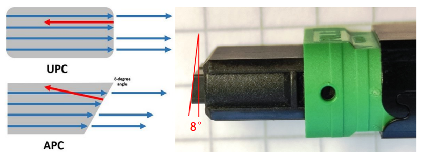
MPO-12/APC connectors cannot be used with MPO-12/UPC Ultra-flat Polished Connectors which are typically used in 4x25G-NRZ (100G) and 4x50G-PAM4 (200G) transceivers as the fiber polishes are different and will not mate.
The split ends can support either OSFP and/or QSFP112 transceivers at the same time depending on the adapter type.
The MFP7E40-Nxxx Fiber Splitter Cable Application:
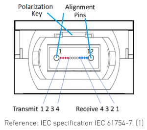
Transceivers have alignment pins for precise positioning of the cable connector against the optical beams. The fiber cable has alignment holes matching the transceiver’s pins.
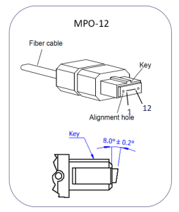
Single-Mode Fiber Cable with MPO/APC Connectors:
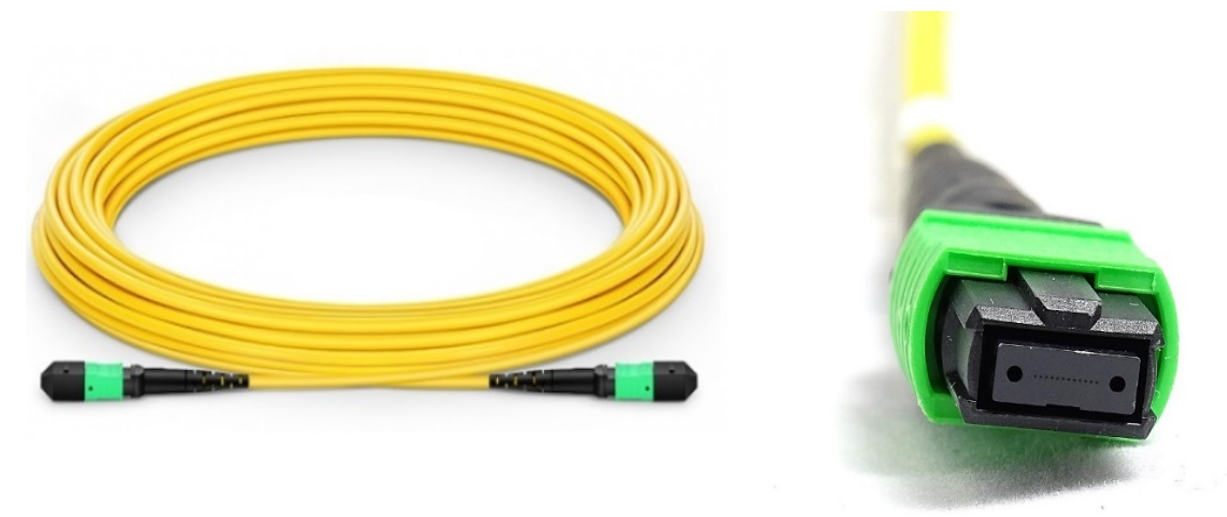
The MPO connectors are the angle-polished (APC) type which provide minimal reflection of the optical signal for optimal signal integrity.
Detail of the MPO/APC Connector:
The MFP7E30-Nxxx fiber cables have 8 individual fibers, 4 in each direction. A positioning key together with the alignment pins define the fiber position numbering scheme
Transceivers have alignment pins for precise positioning of the cable connector against the optical beams. The fiber cable has alignment holes matching the transceiver’s pins.
MPO Connector with Alignment Holes and Positioning Key:
Optical Receptacle and Lane Assignment (transceiver, front view):
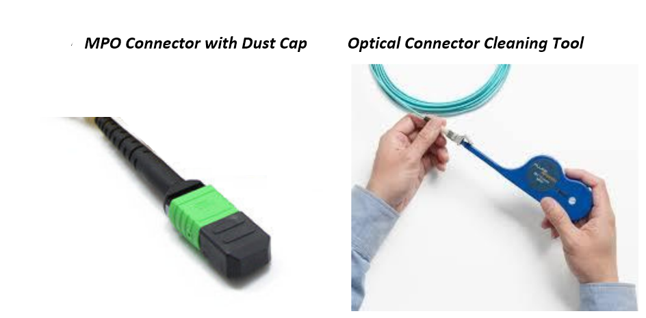
The cable is shipped with dust caps which protect the connectors from contamination during shipment and installation. The caps should stay in place until the cable is plugged in at the time of installation. Prior to insertion of the fiber cable into the transceiver, always clean both the cable and the transceiver connector using optical connector cleaners to remove any accidental contamination. Liquids must not be applied.
Fiber cables have no conductive parts and are not ESD sensitive. However, they plug into ESD sensitive transceivers. Due to that, standard ESD handling precautions must be observed during installation.