Appendix: Optical Connector
The optical port in the parallel 2 x 4-lane optical transceiver is a male MPO connector with alignment pins, mating with fiber-optic cables with female MPO connector. The connector contains a 12-channel MT ferrule.
QSFP+ Optical Receptacle and Channel Orientation for Male MPO Connector
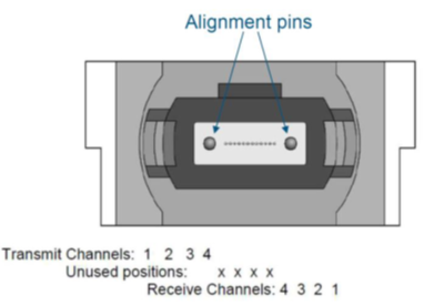
QSFP+ Optical Lane Assignment (Front View of Male MPO Receptacle)
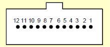
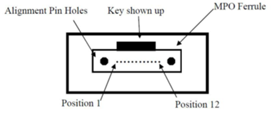
Female MPO Cable Connector Optical Lane Assignment
Reference: IEC specification IEC 61754-7.
The fiber that connects with the transmitter’s lane 1 must end at receiver lane 1 at the far end of the cable. Position 1 of the MPO connector at the near end of the cable connects to position 12 of the opposite MPO connector. This calls for a crossed MPO cable, which is the standard for MPO patch cables.
The fiber is standard OM3 or OM4 multi-mode fiber. The maximum length is found in the Optical Specifications table.
MPO to MPO Patch Cable Fiber Position
Left Cord | Connection | Right Cord |
1 | ---> | 12 |
2 | ---> | 11 |
3 | ---> | 10 |
4 | ---> | 9 |
5 | Not Connected | 8 |
6 | Not Connected | 7 |
7 | Not Connected | 6 |
8 | Not Connected | 5 |
9 | <--- | 4 |
10 | <--- | 3 |
11 | <--- | 2 |
12 | <--- | 1 |
Multiple MPO patch cables can be connected in series, but each added connector pair increases modal dispersion in the link which again impairs performance. An odd number of ‘crosses’ must be used between transceivers at the two ends.