RDG for DPF with HBN DPU Service
Created on September 10, 2025
Scope
This Reference Deployment Guide (RDG) provides detailed instructions for deploying a Kubernetes (K8s) cluster using the DOCA Platform Framework (DPF). The guide focuses on setting up an accelerated Host-Based Networking (HBN) service on NVIDIA® BlueField®-3 DPUs to deliver secure, isolated, and hardware-accelerated environments.
This guide is designed for experienced system administrators, system engineers, and solution architects who seek to deploy high-performance Kubernetes clusters with Host-Based Networking enabled on NVIDIA BlueField DPUs.
This reference implementation, as the name implies, is a specific, opiniated deployment example designed to address the use case described above.
While other approaches may exist to implement similar solutions, this document provides a detailed guide for this particular method.
Abbreviations and Acronyms
Term | Definition | Term | Definition |
BFB | BlueField Bootstream (OS Image) | MAAS | Metal as a Service |
BGP | Border Gateway Protocol | RDG | Reference Deployment Guide |
CNI | Container Network Interface | RDMA | Remote Direct Memory Access |
CSI | Container Storage Interface | SFC | Service Function Chaining |
DOCA | Data Center Infrastructure-on-a-Chip Architecture | SR-IOV | Single Root Input/Output Virtualization |
DPF | DOCA Platform Framework | TOR | Top of Rack |
DPU | Data Processing Unit | VLAN | Virtual LAN (Local Area Network) |
GENEVE | Generic Network Virtualization Encapsulation | VNI | Virtual Network Interface |
HBN | Host Based Networking | VRF | Virtual Router/Forwarder |
IPAM | IP Address Management | VRR | Virtual Router Redundancy |
K8S | Kubernetes | VTEP | Virtual Tunnel End Point |
Introduction
The NVIDIA BlueField-3 Data Processing Unit (DPU) is a 400 Gb/s infrastructure compute platform designed for line-rate processing of software-defined networking, storage, and cybersecurity workloads. It combines powerful compute resources, high-speed networking, and advanced programmability to deliver hardware-accelerated, software-defined solutions for modern data centers.
NVIDIA DOCA unleashes the full potential of the BlueField platform by enabling rapid development of applications and services that offload, accelerate, and isolate data center workloads.
One such service is Host-Based Networking (HBN) - a DOCA-enabled solution that allows network architects to design networks based on Layer 3 (L3) protocols. HBN enables routing on the server side by using BlueField as a BGP router. It encapsulates key networking functions in a containerized service pod, deployed directly on the BlueField’s ARM cores.
However, deploying and managing DPUs and their associated DOCA services, especially at scale, presents operational challenges. Without a robust provisioning and orchestration system, tasks such as lifecycle management, service deployment, and network configuration for service function chaining (SFC) can quickly become complex and error prone. This is where the DOCA Platform Framework (DPF) comes into play.
DPF automates the full DPU lifecycle, streamlines the deployment of DOCA services, and simplifies advanced network configurations. With DPF, services such as HBN can be deployed seamlessly, allowing for efficient offloading and intelligent routing of traffic through the DPU data plane.
By leveraging DPF, users can scale and automate DPU management across Kubernetes customer environments - optimizing performance while simplifying operations.
As part of the reference implementation, open-source components outside the scope of DPF (e.g., MAAS, pfSense, Kubespray) are used to simulate a realistic customer deployment environment.
The guide includes the full end-to-end deployment process, including:
- Infrastructure provisioning
- DPF deployment
- DPU provisioning
- Service configuration and deployment
- Service chaining
It also demonstrates some performance optimizations, with results validated through standard RDMA and TCP workload tests.
References
- NVIDIA BlueField DPU
- NVIDIA DOCA
- NVIDIA DOCA HBN Service
- NVIDIA DPF Release Notes
- NVIDIA DPF GitHub Repository
- NVIDIA DPF System Overview
- NVIDIA DPF with HBN User Guide
- NVIDIA Ethernet Switching
- NVIDIA Cumulus Linux
- NVIDIA Network Operator
- What is K8s?
- Kubespray
- RDG for DPF with OVN-Kubernetes and HBN Services
Solution Architecture
Key Components and Technologies
NVIDIA BlueField® Data Processing Unit (DPU)
The NVIDIA® BlueField® data processing unit (DPU) ignites unprecedented innovation for modern data centers and supercomputing clusters. With its robust compute power and integrated software-defined hardware accelerators for networking, storage, and security, BlueField creates a secure and accelerated infrastructure for any workload in any environment, ushering in a new era of accelerated computing and AI.
NVIDIA DOCA Software Framework
NVIDIA DOCA™ unlocks the potential of the NVIDIA® BlueField® networking platform. By harnessing the power of BlueField DPUs and SuperNICs, DOCA enables the rapid creation of applications and services that offload, accelerate, and isolate data center workloads. It lets developers create software-defined, cloud-native, DPU- and SuperNIC-accelerated services with zero-trust protection, addressing the performance and security demands of modern data centers.
10/25/40/50/100/200 and 400G Ethernet Network Adapters
The industry-leading NVIDIA® ConnectX® family of smart network interface cards (SmartNICs) offer advanced hardware offloads and accelerations.
NVIDIA Ethernet adapters enable the highest ROI and lowest Total Cost of Ownership for hyperscale, public and private clouds, storage, machine learning, AI, big data, and telco platforms.
The NVIDIA® LinkX® product family of cables and transceivers provides the industry’s most complete line of 10, 25, 40, 50, 100, 200, and 400GbE in Ethernet and 100, 200 and 400Gb/s InfiniBand products for Cloud, HPC, hyperscale, Enterprise, telco, storage and artificial intelligence, data center applications.
NVIDIA Spectrum Ethernet Switches
Flexible form-factors with 16 to 128 physical ports, supporting 1GbE through 400GbE speeds.
Based on a ground-breaking silicon technology optimized for performance and scalability, NVIDIA Spectrum switches are ideal for building high-performance, cost-effective, and efficient Cloud Data Center Networks, Ethernet Storage Fabric, and Deep Learning Interconnects.
NVIDIA combines the benefits of NVIDIA Spectrum™ switches, based on an industry-leading application-specific integrated circuit (ASIC) technology, with a wide variety of modern network operating system choices, including NVIDIA Cumulus® Linux , SONiC and NVIDIA Onyx®.
NVIDIA® Cumulus® Linux is the industry's most innovative open network operating system that allows you to automate, customize, and scale your data center network like no other.
The NVIDIA Network Operator simplifies the provisioning and management of NVIDIA networking resources in a Kubernetes cluster. The operator automatically installs the required host networking software - bringing together all the needed components to provide high-speed network connectivity. These components include the NVIDIA networking driver, Kubernetes device plugin, CNI plugins, IP address management (IPAM) plugin and others. The NVIDIA Network Operator works in conjunction with the NVIDIA GPU Operator to deliver high-throughput, low-latency networking for scale-out, GPU computing clusters.
Kubernetes is an open-source container orchestration platform for deployment automation, scaling, and management of containerized applications.
Kubespray is a composition of Ansible playbooks, inventory, provisioning tools, and domain knowledge for generic OS/Kubernetes clusters configuration management tasks and provides:
- A highly available cluster
- Composable attributes
- Support for most popular Linux distributions
RDMA is a technology that allows computers in a network to exchange data without involving the processor, cache or operating system of either computer.
Like locally based DMA, RDMA improves throughput and performance and frees up compute resources.
Solution Design
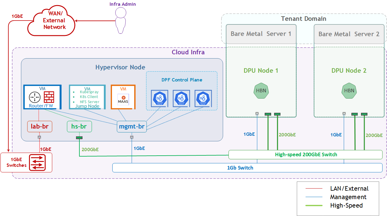
Solution Logical Design
The logical design includes the following components:
1 x Hypervisor node (KVM-based) with ConnectX-7
- 1 x Firewall VM
- 1 x Jump VM
- 1 X MaaS VM
- 3 x K8s Master VMs running all K8s management components
- 2 x Worker nodes (PCI Gen5), each with 1 x BlueField-3 NIC
- Single High-Speed (HS) switch
- 1 Gb Host Management network
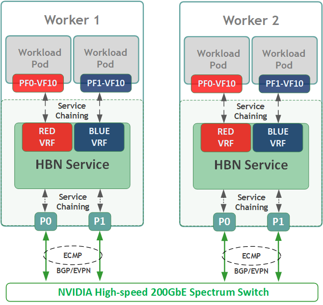
HBN service Logical Design
In this document, we will create two isolated networks on each worker node; one based on virtual function VF10 of PF0, and another based on virtual function VF10 of PF1.
Each network connects through the HBN service to a separate VLAN/VNI, on separate VRFs - RED and BLUE.
We will assign these virtual functions to workload pods as a secondary network using the hostdev plugin. Then we'll demonstrate accelerated RDMA and TCP traffic between pods that run on different workers within the same network (e.g., RED network) and validate network isolation between pods connected to different networks (RED vs BLUE).
If you are interested in accelerating the primary Kubernetes network, please refer to this RDG that covers DPF with both the HBN and OVN-Kubernetes services and the deployment of additional DOCA Services.
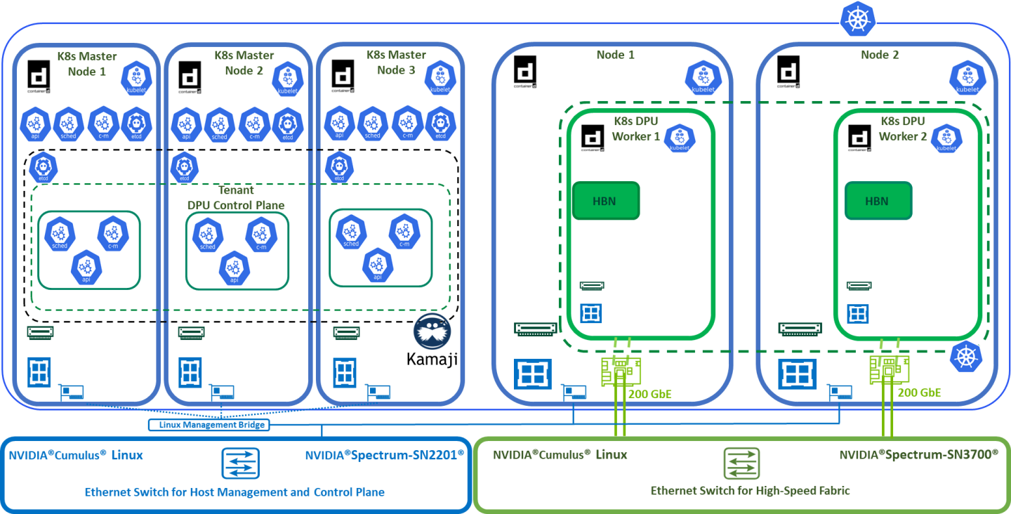
K8s Cluster Logical Design
The following K8s logical design illustration highlights the main components of the DPF system, including:
- 3 x K8s Master Node VMs running all K8s management components
- 2 x K8s Worker Nodes (x86)
- 2 x K8s DPU Workers running the DOCA service (HBN)
- 1 x Kamaji (K8s Control-Plane Manager)
- 1 x Tenant DPU Control Plane (Tenant Cluster)
- Connectivity to High-Speed and 1GbE networks
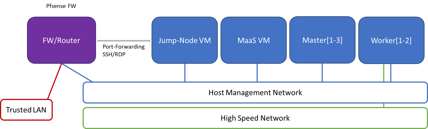
Firewall Design
The pfSense firewall in this solution serves two key roles:
- Firewall – provides an isolated environment for the DPF system, ensuring secure operations
- Router – enables Internet access for the management network
Port-forwarding rules for SSH and RDP are configured on the firewall to route traffic to the jump node’s IP address on the host management network. From the jump node, administrators can manage and access various devices in the setup, as well as handle the deployment of both the Kubernetes (K8s) cluster and DPF components.
The following diagram illustrates the firewall design used in this solution:
Software Stack Components
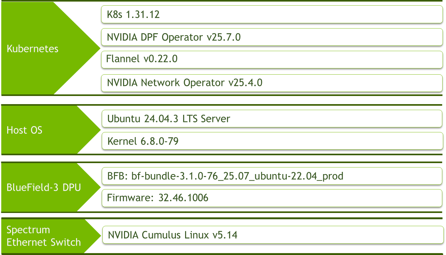
Make sure to use the exact same versions for the software stack as described above.
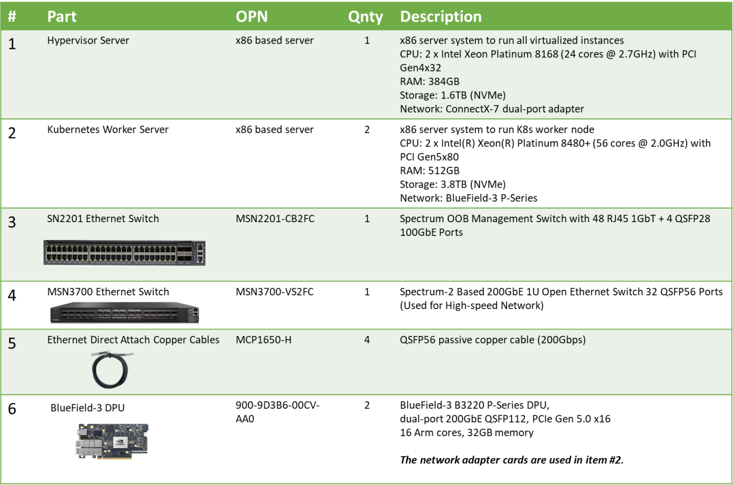
Bill of Materials
Deployment and Configuration
Node and Switch Definitions
The following definitions and parameters are used to deploy the demonstrated fabric:
Switches Ports Usage | ||
Hostname | Rack ID | Ports |
| 1 | swp1-4 |
| 1 | swp1-3 |
Hosts | |||||
Rack | Server Type | Server Name | Switch Port | IP and NICs | Default Gateway |
Rack1 | Hypervisor Node |
| mgmt-switch: | mgmt-br (interface eno2): - lab-br (interface eno1): Trusted LAN IP | Trusted LAN GW |
Rack1 | Worker Node |
| mgmt-switch: hs-switch: | ens15f0: 10.0.110.21/24 ens5f0np0/ens5f1np1: 10.0.120.0/22 | 10.0.110.254 |
Rack1 | Worker Node |
| mgmt-switch: hs-switch: | ens15f0: 10.0.110.22/24 ens5f0np0/ens5f1np1: 10.0.120.0/22 | 10.0.110.254 |
Rack1 | Firewall (Virtual) |
| - | LAN (mgmt-br): 10.0.110.254/24 WAN (lab-br): Trusted LAN IP | Trusted LAN GW |
Rack1 | Jump Node (Virtual) |
| - | enp1s0: 10.0.110.253/24 | 10.0.110.254 |
Rack1 | MaaS (Virtual) |
| - | enp1s0: 10.0.110.252/24 | 10.0.110.254 |
Rack1 | Master Node (Virtual) |
| - | enp1s0: 10.0.110.1/24 | 10.0.110.254 |
Rack1 | Master Node (Virtual) |
| - | enp1s0: 10.0.110.2/24 | 10.0.110.254 |
Rack1 | Master Node (Virtual) |
| - | enp1s0: 10.0.110.3/24 | 10.0.110.254 |
Wiring
Hypervisor Node

K8s Worker Node

Fabric Configuration
Updating Cumulus Linux
As a best practice, make sure to use the latest released Cumulus Linux NOS version.
For information on how to upgrade Cumulus Linux, refer to the Cumulus Linux User Guide.
Configuring the Cumulus Linux Switch
Configure the SN3700 switch (hs-switch) as follows:
SN3700 Switch Console
            nv set interface lo ip address 11.0.0.101/32
nv set interface lo type loopback
nv set interface swp1-4 link state up
nv set interface swp1-4 type swp
nv set router bgp autonomous-system 65001
nv set router bgp enable on
nv set router bgp graceful-restart mode full
nv set router bgp router-id 11.0.0.101
nv set vrf default router bgp address-family ipv4-unicast enable on
nv set vrf default router bgp address-family ipv4-unicast redistribute connected enable on
nv set vrf default router bgp address-family ipv6-unicast enable on
nv set vrf default router bgp address-family ipv6-unicast redistribute connected enable on
nv set vrf default router bgp enable on
nv set evpn enable on
nv set vrf default router bgp neighbor swp1-4 peer-group hbn
nv set vrf default router bgp neighbor swp1-4 type unnumbered
nv set vrf default router bgp path-selection multipath aspath-ignore on
nv set vrf default router bgp peer-group hbn remote-as external
nv set vrf default router bgp address-family l2vpn-evpn enable on
nv set vrf default router bgp peer-group hbn address-family l2vpn-evpn enable on
nv config apply -y
Configure the SN2201 switch (mgmt-switch) as follows:
SN2201 Switch Console
            nv set bridge domain br_default untagged 1
nv set interface swp1-3 link state up
nv set interface swp1-3 type swp
nv set interface swp1-3 bridge domain br_default
nv config apply -y
Host Configuration
Enure that SR-IOV is enabled in the BIOS settings on the worker node servers, and that the servers are tuned for maximum performance.
Make sure all worker nodes have the same PCIe placement for the BlueField-3 NIC and that they show the same interface name.
Hypervisor Installation and Configuration
The hypervisor used in this Reference Deployment Guide (RDG) is based on Ubuntu 24.04 with KVM.
While this document does not detail the KVM installation process, it is important to note that the setup requires the following ISOs to deploy the Firewall, Jump, and MaaS virtual machines (VMs):
- Ubuntu 24.04
- pfSense-CE-2.7.2
To implement the solution, two Linux bridges must be created on the hypervisor:
Ensure a DHCP record is configured for the lab-br bridge interface in your trusted LAN to assign it an IP address.
lab-br– connects the Firewall VM to the trusted LAN.mgmt-br– Connects the various VMs to the host management network.
Hypervisor netplan configuration
            network:
    ethernets:
        eno1:
            dhcp4: false
        eno2:
            dhcp4: false
    bridges:
      lab-br:
         interfaces: [eno1]
         dhcp4: true
      mgmt-br:
         interfaces: [eno2]
         dhcp4: false
    version: 2
Apply the configuration:
Hypervisor Console
$ sudo netplan apply
Prepare Infrastructure Servers
Firewall VM - pfSense Installation and Interface Configuration
Download the pfSense CE (Community Edition) ISO to your hypervisor and proceed with the software installation.
Suggested spec:
- vCPU: 2
- RAM: 2GB
- Storage: 10GB
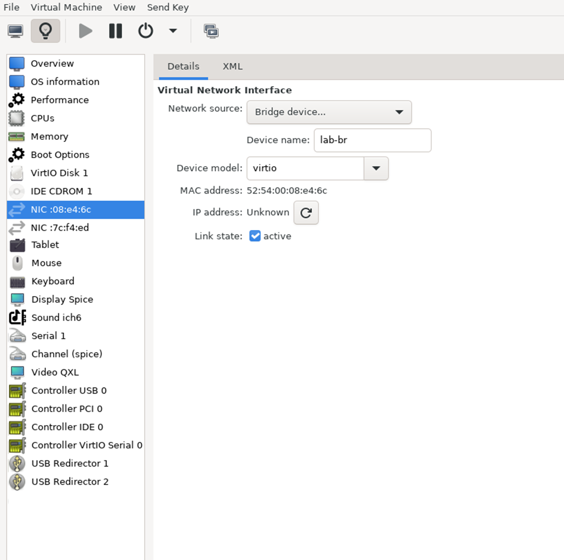
Network interfaces
- Bridge device connected to
lab-br - Bridge device connected to
mgmt-br
- Bridge device connected to
The Firewall VM must be connected to the two Linux bridges on the hypervisor. Before beginning the installation, ensure that three virtual network interfaces of type "Bridge device" are configured. Each interface should be connected to a different bridge (lab-br and mgmt-br) as illustrated in the diagram below.
After completing the installation, the setup wizard displays a menu with several options, such as "Assign Interfaces" and "Reboot System." During this phase, configure the network interfaces for the Firewall VM:
Select Option 2: "Set interface(s) IP address" and configure the interfaces as follows:
- WAN – Trusted LAN IP (Static/DHCP)
- LAN – Static IP
10.0.110.254/24
- Once the interface configuration is complete, use a web browser within the host management network to access the Firewall web interface and finalize the configuration.
Next, proceed with the installation of the Jump VM. This VM will serve as a platform for running a browser to access the Firewall’s web interface for post-installation configuration.
Jump VM
Suggested specifications:
- vCPU: 4
- RAM: 8GB
- Storage: 25GB
- Network interface: Bridge device, connected to
mgmt-br
Procedure:
Proceed with a standard Ubuntu 24.04 installation. Use the following login credentials across all hosts in this setup:
Username
Password
depuser
user
Enable internet connectivity and DNS resolution by creating the following Netplan configuration:
NoteUse
10.0.110.254as a temporary DNS nameserver until the MaaS VM is installed and configured. After completing the MaaS installation, update the Netplan file to replace this address with the MaaS IP:10.0.110.252.Jump Node netplan
network: ethernets: enp1s0: dhcp4:
falseaddresses: [10.0.110.253/24] nameservers: search: [dpf.rdg.local.domain] addresses: [10.0.110.254] routes: - to:defaultvia:10.0.110.254version:2Apply the configuration:
Jump Node Console
depuser@jump:~$ sudo netplan apply
Update and upgrade the system:
Jump Node Console
            depuser@jump:~$ sudo apt update -y
depuser@jump:~$ sudo apt upgrade -y
Install and configure the Xfce desktop environment and XRDP (complementary packages for RDP):
Jump Node Console
            depuser@jump:~$ sudo apt install -y xfce4 xfce4-goodies
depuser@jump:~$ sudo apt install -y lightdm-gtk-greeter
depuser@jump:~$ sudo apt install -y xrdp
depuser@jump:~$ echo "xfce4-session" | tee .xsession
depuser@jump:~$ sudo systemctl restart xrdp
Install Firefox for accessing the Firewall web interface:
Jump Node Console
$ sudo apt install -y firefox
Install and configure an NFS server with the
/mnt/dpf_sharedirectory:Jump Node Console
            $ sudo apt install -y nfs-server
$ sudo mkdir -m 777 /mnt/dpf_share
$ sudo vi /etc/exports
Add the following line to
/etc/exports:Jump Node Console
/mnt/dpf_share 10.0.110.0/24(rw,sync,no_subtree_check)
Restart the NFS server:
Jump Node Console
$ sudo systemctl restart nfs-server
Create the directory
bfbunder/mnt/dpf_sharewith the same permissions as the parent directory:Jump Node Console
$ sudo mkdir -m 777 /mnt/dpf_share/bfb
Generate an SSH key pair for
depuserin the jump node (later on will be imported to the admin user in MaaS to enable password-less login to the provisioned servers):Jump Node Console
depuser@jump:~$ ssh-keygen -t rsa
Finally, reboot the VM to load the graphical interface:
Jump Node Console
depuser@jump:~$ sudo reboot
After setting up the port-forwarding rules on the firewall (see next steps), you will be able to remotely log into the graphical interface of the Jump node via RDP and SSH.
Please note that you can not be logged in to both the local graphical console and the RDP client at the same time. Be sure to log out before switching to an RDP connection.
Firewall VM – Web Configuration
From the Jump node graphical interface, open a Firefox web browser and go to the pfSense web UI (http://10.0.110.254; default credentials are admin/pfsense). You should see a page similar to the following:
The IP addresses from the trusted LAN network under "DNS servers" and "Interfaces - WAN" are blurred.

Proceed with the following configurations:
The following screenshots display only part of the configuration view. Be sure to follow all of the steps mentioned below!
Interfaces
- WAN (lab-br) – mark “Enable interface”, unmark “Block private networks and loopback addresses”
LAN (mgmt-br) – mark “Enable interface”, “IPv4 configuration type”: Static IPv4 ("IPv4 Address": 10.0.110.254/24, "IPv4 Upstream Gateway": None)

Firewall:
- NAT -> Port Forward -> Add rule -> “Interface”: WAN, “Address Family”: IPv4, “Protocol”: TCP, “Destination”: WAN address, “Destination port range”: (“From port”: SSH, “To port”: SSH), “Redirect target IP”: (“Type”: Address or Alias, “Address”: 10.0.110.253), “Redirect target port”: SSH, “Description”: NAT SSH
- NAT -> Port Forward -> Add rule -> “Interface”: WAN , “Address Family”: IPv4 , “Protocol”: TCP , “Destination”: WAN address , “Destination port range”: (“From port”: MS RDP , “To port”: MS RDP ), “Redirect target IP”: (“Type”: Address or Alias , “Address”: 10.0.110.253 ), “Redirect target port”: MS RDP , “Description”: NAT RDP
MaaS VM
Suggested specifications:
- vCPU: 4
- RAM: 4GB
- Storage: 50GB
- Network interface: Bridge device, connected to
mgmt-br
Procedure:
- Perform a regular Ubuntu installation on the MaaS VM.
Create the following Netplan configuration to enable internet connectivity and DNS resolution:
NoteUse
10.0.110.254as a temporary DNS nameserver. After the MaaS installation, replace this with the MaaS IP address (10.0.110.252) in both the Jump and MaaS VM Netplan files.MaaS netplan
network: ethernets: enp1s0: dhcp4:
falseaddresses: [10.0.110.252/24] nameservers: search: [dpf.rdg.local.domain] addresses: [10.0.110.254] routes: - to:defaultvia:10.0.110.254version:2Apply the netplan configuration:
MaaS Console
depuser@maas:~$ sudo netplan apply
Update and upgrade the system:
MaaS Console
            depuser@maas:~$ sudo apt update -y
depuser@maas:~$ sudo apt upgrade -y
Install PostgreSQL and configure the database for MaaS:
MaaS Console
            $ sudo -i
# apt install -y postgresql
# systemctl disable --now systemd-timesyncd
# export MAAS_DBUSER=maasuser
# export MAAS_DBPASS=maaspass
# export MAAS_DBNAME=maas
# sudo -i -u postgres psql -c "CREATE USER \"$MAAS_DBUSER\" WITH ENCRYPTED PASSWORD '$MAAS_DBPASS'"
# sudo -i -u postgres createdb -O "$MAAS_DBUSER" "$MAAS_DBNAME"
Install MaaS:
MaaS Console
# snap install --channel=3.5/stable maas
Initialize MaaS:
MaaS Console
# maas init region+rack --maas-url http://10.0.110.252:5240/MAAS --database-uri "postgres://$MAAS_DBUSER:$MAAS_DBPASS@localhost/$MAAS_DBNAME"
Create an admin account:
MaaS Console
# maas createadmin --username admin --password admin --email admin@example.com
Save the admin API key:
MaaS Console
# maas apikey --username admin > admin-apikey
Log in to the MaaS server:
MaaS Console
# maas login admin http://localhost:5240/MAAS "$(cat admin-apikey)"
Configure MaaS (Substitute <Trusted_LAN_NTP_IP> and <Trusted_LAN_DNS_IP> with the IP addresses in your environment):
MaaS Console
            # maas admin domain update maas name="dpf.rdg.local.domain"
# maas admin maas set-config name=ntp_servers value="<Trusted_LAN_NTP_IP>"
# maas admin maas set-config name=network_discovery value="disabled"
# maas admin maas set-config name=upstream_dns value="<Trusted_LAN_DNS_IP>"
# maas admin maas set-config name=dnssec_validation value="no"
# maas admin maas set-config name=default_osystem value="ubuntu"
Define and configure IP ranges and subnets:
MaaS Console
            # maas admin ipranges create type=dynamic start_ip="10.0.110.51" end_ip="10.0.110.120"
# maas admin ipranges create type=dynamic start_ip="10.0.110.21" end_ip="10.0.110.30"
# maas admin ipranges create type=reserved start_ip="10.0.110.10" end_ip="10.0.110.10" comment="c-plane VIP"
# maas admin ipranges create type=reserved start_ip="10.0.110.200" end_ip="10.0.110.200" comment="kamaji VIP"
# maas admin ipranges create type=reserved start_ip="10.0.110.251" end_ip="10.0.110.254" comment="dpfmgmt"
# maas admin vlan update 0 untagged dhcp_on=True primary_rack=maas
# maas admin dnsresources create fqdn=kube-vip.dpf.rdg.local.domain ip_addresses=10.0.110.10
# maas admin dnsresources create fqdn=jump.dpf.rdg.local.domain ip_addresses=10.0.110.253
# maas admin dnsresources create fqdn=fw.dpf.rdg.local.domain ip_addresses=10.0.110.254
# maas admin fabrics create
Success.
Machine-readable output follows:
{
"class_type": null,
"name": "fabric-1",
"id": 1,
...
Configure static DHCP leases for the worker nodes (replace MAC address as appropriate with your workers MGMT interface MAC ):
MaaS Console
            # maas admin reserved-ips create ip="10.0.110.21" mac_address="04:32:01:60:0d:da" comment="worker1"
# maas admin reserved-ips create ip="10.0.110.22" mac_address="04:32:01:5f:cb:e0" comment="worker2"
Complete MaaS setup:
- Connect to the Jump node GUI and access the MaaS UI at
http://10.0.110.252:5240/MAAS. - On the first page, verify the "Region Name" and "DNS Forwarder," then continue.
On the image selection page, select Ubuntu 24.04 LTS (amd64) and sync the image.

Import the previously generated SSH key (
id_rsa.pub) for thedepuserinto the MaaS admin user profile and finalize the setup.
- Connect to the Jump node GUI and access the MaaS UI at
Go to Settings → Deploy, set "Default OS release" to Ubuntu 24.04 LTS Noble Numbat, and save.

- Update the DNS nameserver IP address in both Jump and MaaS VM Netplan files from
10.0.110.254to10.0.110.252and reapply the configuration.
K8s Master VMs
Suggested specifications:
- vCPU: 8
- RAM: 16GB
- Storage: 100GB
- Network interface: Bridge device, connected to
mgmt-br
Before provisioning the Kubernetes (K8s) Master VMs with MaaS, create the required virtual disks with empty storage. Use the following one-liner to create three 100 GB QCOW2 virtual disks:
Hypervisor Console
$ for i in $(seq 1 3); do qemu-img create -f qcow2 /var/lib/libvirt/images/master$i.qcow2 100G; done
This command generates the following disks in the
/var/lib/libvirt/images/directory:master1.qcow2master2.qcow2master3.qcow2
Configure VMs in virt-manager:
Open virt-manager and create three virtual machines:
- Assign the corresponding virtual disk (
master1.qcow2,master2.qcow2, ormaster3.qcow2) to each VM. - Configure each VM with the suggested specifications (vCPU, RAM, storage, and network interface).
- Assign the corresponding virtual disk (
- During the VM setup, ensure the NIC is selected under the Boot Options tab. This ensures the VMs can PXE boot for MaaS provisioning.
- Once the configuration is complete, shut down all the VMs.
- After the VMs are created and configured, proceed to provision them via the MaaS interface. MaaS will handle the OS installation and further setup as part of the deployment process.
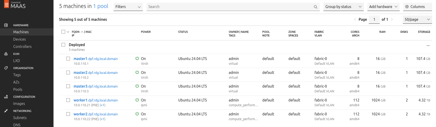
Provision Master VMs and Worker Nodes Using MaaS
Master VMs
Install virsh and Set Up SSH Access
SSH to the MaaS VM from the Jump node:
MaaS Console
            depuser@jump:~$ ssh maas
depuser@maas:~$ sudo -i
Install the
virshclient to communicate with the hypervisor:MaaS Console
# apt install -y libvirt-clients
Generate an SSH key for the
rootuser and copy it to the hypervisor user in thelibvirtdgroup:MaaS Console
            # ssh-keygen -t rsa
# ssh-copy-id ubuntu@<hypervisor_MGMT_IP>
Verify SSH access and
virshcommunication with the hypervisor:MaaS Console
# virsh -c qemu+ssh://ubuntu@<hypervisor_MGMT_IP>/system list --all
Expected output:
MaaS Console
             Id   Name          State
------------------------------
 1    fw     running
 2    jump   running
 3    maas   running
 -    master1       shut off
 -    master2       shut off
 -    master3       shut off
Copy the SSH key to the required MaaS directory (for snap-based installations):
MaaS Console
            # mkdir -p /var/snap/maas/current/root/.ssh
# cp .ssh/id_rsa* /var/snap/maas/current/root/.ssh/
Get MAC Addresses of the Master VMs
Retrieve the MAC addresses of the Master VMs:
MaaS Console
# for i in $(seq 1 3); do virsh -c qemu+ssh://ubuntu@<hypervisor_MGMT_IP>/system dumpxml master$i | grep 'mac address'; done
Example output:
MaaS Console
            <mac address='52:54:00:a9:9c:ef'/>
<mac address='52:54:00:19:6b:4d'/>
<mac address='52:54:00:68:39:7f'/>
Add Master VMs to MaaS
Add the Master VMs to MaaS:
InfoOnce added, MaaS will automatically start the newly added VMs commissioning (discovery and introspection).
MaaS Console
            # maas admin machines create hostname=master1 architecture=amd64/generic mac_addresses='52:54:00:a9:9c:ef' power_type=virsh power_parameters_power_address=qemu+ssh://ubuntu@<hypervisor_MGMT_IP>/system power_parameters_power_id=master1 skip_bmc_config=1 testing_scripts=none
Success.
Machine-readable output follows:
{
    "description": "",
    "status_name": "Commissioning",
...
    "status": 1,
...
    "system_id": "c3seyq",
...
    "fqdn": "master1.dpf.rdg.local.domain",
    "power_type": "virsh",
...
    "status_message": "Commissioning",
    "resource_uri": "/MAAS/api/2.0/machines/c3seyq/"
}

# maas admin machines create hostname=master2 architecture=amd64/generic mac_addresses='52:54:00:19:6b:4d' power_type=virsh power_parameters_power_address=qemu+ssh://ubuntu@<hypervisor_MGMT_IP>/system power_parameters_power_id=master2 skip_bmc_config=1 testing_scripts=none

# maas admin machines create hostname=master3 architecture=amd64/generic mac_addresses='52:54:00:68:39:7f' power_type=virsh power_parameters_power_address=qemu+ssh://ubuntu@<hypervisor_MGMT_IP>/system power_parameters_power_id=master3 skip_bmc_config=1 testing_scripts=none
- Repeat the command for
master2andmaster3with their respective MAC addresses. Verify commissioning by waiting for the status to change to "Ready" in MaaS.

After commissioning, the next phase is deployment (OS provisioning).
Configure Master VMs Network
To ensure persistence across reboots, assign a static IP address to the management interface of the master nodes.
For each Master VM:
Navigate to Network and click "actions" near the management interface (a small arrowhead pointing down). Then select "Edit Physical".
Configure as follows:
- Subnet: 10.0.110.0/24
- IP Mode: Static Assign
Address: Assign
10.0.110.1formaster1,10.0.110.2formaster2, and10.0.110.3formaster3.
- Save the interface settings for each VM.
Deploy Master VMs Using Cloud-Init
Use the following cloud-init script to configure the necessary software and ensure persistency:
Master nodes cloud-init
#cloud-config system_info: default_user: name: depuser passwd:
"$6$jOKPZPHD9XbG72lJ$evCabLvy1GEZ5OR1Rrece3NhWpZ2CnS0E3fu5P1VcZgcRO37e4es9gmriyh14b8Jx8gmGwHAJxs3ZEjB0s0kn/"lock_passwd:falsegroups: [adm, audio, cdrom, dialout, dip, floppy, lxd, netdev, plugdev, sudo, video] sudo: ["ALL=(ALL) NOPASSWD:ALL"] shell: /bin/bash ssh_pwauth: True package_upgrade:trueruncmd: - apt-get update - apt-get -y install nfs-commonDeploy the master VMs:
- Select all three Master VMs → Actions → Deploy.
- Toggle Cloud-init user-data and paste the cloud-init script.
Start the deployment and wait until the status to changes to "Ubuntu 24.04 LTS".


Verify Deployment
SSH into the Master VMs from the Jump node:
Jump Node Console
            depuser@jump:~$ ssh master1
depuser@master1:~$
Run
sudowithout a password:Master1 Console
            depuser@master1:~$ sudo -i
root@master1:~#
Verify the installed packages:
Master1 Console
            root@master1:~# apt list --installed | egrep 'nfs-common'
nfs-common/noble,now 1:2.6.4-3ubuntu5 amd64 [installed]
Finalize Setup
Reboot the Master VMs to complete the provisioning.
Master1 Console
root@master1:~# reboot
Worker Nodes
Create Worker Machines in MaaS
Add the worker nodes to MaaS using
ipmias the power type. Replace placeholders with your specific IPMI credentials and IP addresses:MAAS Console
# maas admin machines create hostname=worker1 architecture=amd64 power_type=ipmi power_parameters_power_driver=LAN_2_0 power_parameters_power_user=<IPMI_username_worker1> power_parameters_power_pass=<IPMI_password_worker1> power_parameters_power_address=<IPMI_address_worker1>
Output example:
MaaS Console
            ...
Success.
Machine-readable output follows:
{
    "description": "",
    "status_name": "Commissioning",
...
    "status": 1,
...
    "system_id": "pbskd3",
...
    "fqdn": "worker1.dpf.rdg.local.domain",
...
    "power_type": "ipmi",
...
    "resource_uri": "/MAAS/api/2.0/machines/pbskd3/"
}
Repeat the command for
worker2with its respective credentials:MAAS Console
# maas admin machines create hostname=worker2 architecture=amd64 power_type=ipmi power_parameters_power_driver=LAN_2_0 power_parameters_power_user=<IPMI_username_worker2> power_parameters_power_pass=<IPMI_password_worker2> power_parameters_power_address=<IPMI_address_worker2>
Once added, MaaS automatically starts commissioning the worker nodes (discovery and introspection).
Please ensure the worker nodes are properly configured to allow PXE booting on their management interface. Specific BIOS settings might be required.
Create a Tag for Kernel Parameters
Create an entity called "Tag" to configure kernel parameters for the worker nodes.
In the MaaS UI sidebar, go to Organization → Tags → Create New Tag and define:
- "Tag name":
compute_performance - "Kernel options":
- "Tag name":
Substitute the values for
isolcpus,nohz_full, andrcu_nocbswith the CPU cores from the NUMA node which the BlueField-3 is connected to:NoteIf you are not sure in which NUMA node BlueField is connected to, you can later perform this step after the worker node is deployed (although redeployment would be necessary).
MAAS Console
intel_iommu=on iommu=pt numa_balancing=disable processor.max_cstate=0 isolcpus=28-55,84-111 nohz_full=28-55,84-111 rcu_nocbs=28-55,84-111
Apply the tag:
- Go to Machines → Select a worker node → Configuration → Edit Tag → Select
compute_performance→ Save. - Repeat for the other worker node.
- Go to Machines → Select a worker node → Configuration → Edit Tag → Select
Adjust Network Settings
For each worker node, configure the network interfaces:
Management Adapter:
- Go to Network → Select the host management adapter (e.g.,
ens15f0) → Create Bridge - Name:
br-dpu - Bridge Type: Standard
- Subnet:
10.0.110.0/24 - IP Mode: DHCP
- Save the interface
- Go to Network → Select the host management adapter (e.g.,
Repeat the previous steps for the second worker node.
Deploy Worker Nodes Using Cloud-Init
Use the following cloud-init script for deployment:
Worker node cloud-init
#cloud-config system_info: default_user: name: depuser passwd:
"$6$jOKPZPHD9XbG72lJ$evCabLvy1GEZ5OR1Rrece3NhWpZ2CnS0E3fu5P1VcZgcRO37e4es9gmriyh14b8Jx8gmGwHAJxs3ZEjB0s0kn/"lock_passwd:falsegroups: [adm, audio, cdrom, dialout, dip, floppy, lxd, netdev, plugdev, sudo, video] sudo: ["ALL=(ALL) NOPASSWD:ALL"] shell: /bin/bash ssh_pwauth: True package_upgrade:truewrite_files: - path: /etc/sysctl.d/99-custom-netfilter.conf owner: root:root permissions:'0644'content: | net.bridge.bridge-nf-call-iptables=0runcmd: - apt-get update - apt-get -y install nfs-common - sysctl --system- Deploy the worker nodes by selecting the worker nodes in MaaS → Actions → Deploy → Customize options → Enable Cloud-init user-data → Paste the cloud-init script → Deploy.
Verify Deployment
After the deployment is complete, verify that the worker nodes have been deployed successfully using the following commands:
SSH without password from the jump node:
Jump Node Console
            depuser@jump:~$ ssh worker1
depuser@worker1:~$
Run
sudowithout a password:Worker1 Console
            depuser@worker1:~$ sudo -i
root@worker1:~#
Validate that the
nfs-commonpackage was installed:Worker1 Console
            root@worker1:~# apt list --installed | grep 'nfs-common'
nfs-common/noble,now 1:2.6.4-3ubuntu5 amd64 [installed]
Validate that
/proc/cmdlineis configured with the correct parameters and that IOMMU is indeed inpassthroughmode:Worker1 Console
            root@worker1:~# cat /proc/cmdline
BOOT_IMAGE=/boot/vmlinuz-6.8.0-60-generic root=UUID=5b74560e-130e-42db-a939-58a8d3003cbd ro intel_iommu=on iommu=pt numa_balancing=disable processor.max_cstate=0 isolcpus=28-55,84-111 nohz_full=28-55,84-111 rcu_nocbs=28-55,84-111

root@worker1:~# dmesg | grep 'type: Passthrough'
[    5.068360] iommu: Default domain type: Passthrough (set via kernel command line)
Validate that the
br_netfiltermodule is not loaded:Worker1 Console
            root@worker1:~# lsmod | grep br_netfilter
root@worker1:~#
Validate that the P0 interface has
dhcp4set totrue.Worker1 Console
            root@worker1:~# cat /etc/netplan/50-cloud-init.yaml
network:
...
		ens5f0np0:
            dhcp4: true
            match:
                macaddress: a0:88:c2:46:78:c4
            set-name: ens5f0np0
...
Finalize Deployment
Reboot the worker nodes:
Jump Node Console
root@worker1:~# reboot
The infrastructure is now ready for the K8s deployment.
K8s Cluster Deployment and Configuration
Kubespray Deployment and Configuration
In this solution, the Kubernetes (K8s) cluster is deployed using a modified Kubespray (based on release
v2.28.1
) from the Jump Node, utilizing a non-root depuser account. These Kubespray modifications align with the DPF prerequisites as described in the User Manual and facilitate both cluster deployment and scaling.
Our modified Kubespray installs Flannel CNI as the primary Kubernetes network plugin.
- Download the modified Kubespray archive: modified_kubespray_v2.28.1.tar.gz.
Extract the contents and navigate to the extracted directory:
Jump Node Console
            $ tar -xzf /home/depuser/modified_kubespray_v2.28.1.tar.gz
$ cd kubespray/
depuser@jump:~/kubespray$
Set the K8s API VIP address and DNS record. Replace the values with your own IP address and DNS record if they differ:
Jump Node Console
            depuser@jump:~/kubespray$ sed -i '/# kube_vip_address:/s/.*/kube_vip_address: 10.0.110.10/' inventory/mycluster/group_vars/k8s_cluster/addons.yml
depuser@jump:~/kubespray$ sed -i '/apiserver_loadbalancer_domain_name:/s/.*/apiserver_loadbalancer_domain_name: "kube-vip.dpf.rdg.local.domain"/' roles/kubespray_defaults/defaults/main/main.yml
Install the necessary dependencies and set up the Python virtual environment:
Jump Node Console
            depuser@jump:~/kubespray$ sudo apt -y install python3-pip jq python3.12-venv
depuser@jump:~/kubespray$ python3 -m venv .venv
depuser@jump:~/kubespray$ source .venv/bin/activate
(.venv) depuser@jump:~/kubespray$ python3 -m pip install --upgrade pip
(.venv) depuser@jump:~/kubespray$ pip install -U -r requirements.txt
(.venv) depuser@jump:~/kubespray$ pip install ruamel-yaml
Review and edit the
inventory/mycluster/hosts.yamlfile to define the cluster nodes. The following is the configuration for this deployment:Note- All of the nodes are already labeled and annotated by Kubespray as required by DPF prerequisites.
The worker nodes include additional kubelet configuration which will be applied during their deployment to achieve best performance, allowing:
- Container in Guaranteed pods, requesting an integer number of CPUs, will have dedicated CPU cores on the node.
- The NIC in our example is wired to NUMA node 1. T
o achieve maximum performance, we would need to prevent the pods from getting cores from NUMA 0, so we reserve these cores for the system using the
reservedSystemCPUsoption.
- The workers under the
kube_nodegroup are marked with # to only deploy the cluster with control plane nodes at the beginning (worker nodes will be added later on after the various components that are necessary for the DPF system are installed).
inventory/mycluster/hosts.yaml
all: hosts: master1: ansible_host:
10.0.110.1ip:10.0.110.1access_ip:10.0.110.1master2: ansible_host:10.0.110.2ip:10.0.110.2access_ip:10.0.110.2master3: ansible_host:10.0.110.3ip:10.0.110.3access_ip:10.0.110.3worker1: ansible_host:10.0.110.21ip:10.0.110.21access_ip:10.0.110.21node_labels:"node-role.kubernetes.io/worker":""kubelet_cpu_manager_policy:statickubelet_reservedSystemCPUs:0-27,56-83worker2: ansible_host:10.0.110.22ip:10.0.110.22access_ip:10.0.110.22node_labels:"node-role.kubernetes.io/worker":""kubelet_cpu_manager_policy:statickubelet_reservedSystemCPUs:0-27,56-83children: kube_control_plane: hosts: master1: master2: master3: kube_node: hosts: # worker1: # worker2: etcd: hosts: master1: master2: master3: k8s_cluster: children: kube_control_plane: kube_node:
Deploying Cluster Using Kubespray Ansible Playbook
Run the following command from the Jump Node to initiate the deployment process:
NoteEnsure you are in the Python virtual environment (
.venv) when running the command.Jump Node Console
(.venv) depuser@jump:~/kubespray$ ansible-playbook -i inventory/mycluster/hosts.yaml --become --become-user=root cluster.yml
It takes a while for this deployment to complete. Make sure there are no errors. Successful result example:
 Tip
TipIt is recommended to keep the shell where Kubespray has been running open, as it will be useful later for scaling out the cluster and adding worker nodes.
K8s Deployment Verification
To simplify K8s cluster management from the Jump Host, set up kubectl with bash auto-completion.
Copy
kubectland the kubeconfig file frommaster1to the Jump Host:Jump Node Console
            ## Connect to master1
depuser@jump:~$ ssh master1
depuser@master1:~$ cp /usr/local/bin/kubectl /tmp/
depuser@master1:~$ sudo cp /root/.kube/config /tmp/kube-config
depuser@master1:~$ sudo chmod 644 /tmp/kube-config
In another terminal tab, copy the files to the Jump Host:
Jump Node Console
            depuser@jump:~$ scp master1:/tmp/kubectl /tmp/
depuser@jump:~$ sudo chown root:root /tmp/kubectl
depuser@jump:~$ sudo mv /tmp/kubectl /usr/local/bin/
depuser@jump:~$ mkdir -p ~/.kube
depuser@jump:~$ scp master1:/tmp/kube-config ~/.kube/config
depuser@jump:~$ chmod 600 ~/.kube/config
Enable bash auto-completion for
kubectl:Verify if bash-completion is installed:
Jump Node Console
depuser@jump:~$ type _init_completion
If installed, the output will include:
Jump Node Console
_init_completion is a function
If not installed, install it:
Jump Node Console
depuser@jump:~$ sudo apt install -y bash-completion
Set up the
kubectlcompletion script:Jump Node Console
            depuser@jump:~$ kubectl completion bash | sudo tee /etc/bash_completion.d/kubectl > /dev/null
depuser@jump:~$ bash
Check the status of the nodes in the cluster:
Jump Node Console
depuser@jump:~$ kubectl get nodes
Expected output:
Jump Node Console
            NAME      STATUS     ROLES           AGE   VERSION
master1   Ready      control-plane   42m   v1.31.12
master2   Ready      control-plane   41m   v1.31.12
master3   Ready      control-plane   41m   v1.31.12
Check the pods in all namespaces:
Jump Node Console
depuser@jump:~$ kubectl get pods -A
Expected output:
Jump Node Console
            NAMESPACE     NAME                              READY   STATUS    RESTARTS   AGE
kube-system   coredns-776bb9db5d-cr56m          1/1     Running   0          12m
kube-system   coredns-776bb9db5d-dnhct          1/1     Running   0          12m
kube-system   dns-autoscaler-6ffb84bd6-5kvfc    1/1     Running   0          12m
kube-system   kube-apiserver-master1            1/1     Running   0          14m
kube-system   kube-apiserver-master2            1/1     Running   0          14m
kube-system   kube-apiserver-master3            1/1     Running   0          13m
kube-system   kube-controller-manager-master1   1/1     Running   1          14m
kube-system   kube-controller-manager-master2   1/1     Running   1          14m
kube-system   kube-controller-manager-master3   1/1     Running   1          13m
kube-system   kube-flannel-fm7fr                1/1     Running   0          13m
kube-system   kube-flannel-gtv6l                1/1     Running   0          13m
kube-system   kube-flannel-nqvxs                1/1     Running   0          13m
kube-system   kube-proxy-dspz6                  1/1     Running   0          14m
kube-system   kube-proxy-tntld                  1/1     Running   0          13m
kube-system   kube-proxy-ttfct                  1/1     Running   0          14m
kube-system   kube-scheduler-master1            1/1     Running   1          14m
kube-system   kube-scheduler-master2            1/1     Running   1          13m
kube-system   kube-scheduler-master3            1/1     Running   1          13m
kube-system   kube-vip-master1                  1/1     Running   0          14m
kube-system   kube-vip-master2                  1/1     Running   0          13m
kube-system   kube-vip-master3                  1/1     Running   0          13m
DPF Installation
Software Prerequisites and Required Variables
Start by installing the remaining software perquisites.
Jump Node Console
            ## Connect to master1 to copy helm client utility that was installed during kubespray deployment
$ depuser@jump:~$ ssh master1
depuser@master1:~$ cp /usr/local/bin/helm /tmp/

## In another tab
depuser@jump:~$ scp master1:/tmp/helm /tmp/
depuser@jump:~$ sudo chown root:root /tmp/helm
depuser@jump:~$ sudo mv /tmp/helm /usr/local/bin/

## Verify that envsubst utility is installed
depuser@jump:~$ which envsubst
/usr/bin/envsubst
Proceed to clone the doca-platform Git repository (and make sure to use tag v25.7.0):
Jump Node Console
            $ git clone https://github.com/NVIDIA/doca-platform.git
$ cd doca-platform
$ git checkout v25.7.0
Change to the directory containing the hbn-only readme.md, as all commands will be run from this location:
Jump Node Console
$ cd docs/public/user-guides/host-trusted/use-cases/hbn
Use the following file to define the required variables for the installation:
Replace the values for the variables in the following file with the values that fit your setup. Specifically, pay attention to
DPU_P0andDPUCLUSTER_INTERFACE
manifests/00-env-vars/envvars.env
            ## IP Address for the Kubernetes API server of the target cluster on which DPF is installed.
## This should never include a scheme or a port.
## e.g. 10.10.10.10
export TARGETCLUSTER_API_SERVER_HOST=10.0.110.10

## Port for the Kubernetes API server of the target cluster on which DPF is installed.
export TARGETCLUSTER_API_SERVER_PORT=6443

## Virtual IP used by the load balancer for the DPU Cluster. Must be a reserved IP from the management subnet and not allocated by DHCP.
export DPUCLUSTER_VIP=10.0.110.200

## DPU_P0 is the name of the first port of the DPU. This name must be the same on all worker nodes.
export DPU_P0=ens5f0np0

## Interface on which the DPUCluster load balancer will listen. Should be the management interface of the control plane node.
export DPUCLUSTER_INTERFACE=enp1s0

## IP address to the NFS server used as storage for the BFB.
export NFS_SERVER_IP=10.0.110.253

## The repository URL for the NVIDIA Helm chart registry.
## Usually this is the NVIDIA Helm NGC registry. For development purposes, this can be set to a different repository.
export HELM_REGISTRY_REPO_URL=https://helm.ngc.nvidia.com/nvidia/doca

## The repository URL for the HBN container image.
## Usually this is the NVIDIA NGC registry. For development purposes, this can be set to a different repository.
export HBN_NGC_IMAGE_URL=nvcr.io/nvidia/doca/doca_hbn

## The DPF REGISTRY is the Helm repository URL where the DPF Operator Chart resides.
## Usually this is the NVIDIA Helm NGC registry. For development purposes, this can be set to a different repository.
export REGISTRY=https://helm.ngc.nvidia.com/nvidia/doca

## The DPF TAG is the version of the DPF components which will be deployed in this guide.
export TAG=v25.7.0

## URL to the BFB used in the `bfb.yaml` and linked by the DPUSet.
export BFB_URL="https://content.mellanox.com/BlueField/BFBs/Ubuntu22.04/bf-bundle-3.1.0-76_25.07_ubuntu-22.04_prod.bfb"
Export environment variables for the installation:
Jump Node Console
$ source manifests/00-env-vars/envvars.env
DPF Operator Installation
Create Storage Required by the DPF Operator
The following YAML files define storage (for the BFB image) that are required by the DPF operator.
manifests/01-dpf-operator-installation/nfs-storage-for-bfb-dpf-ga.yaml
            ---
apiVersion: v1
kind: PersistentVolume
metadata:
  name: bfb-pv
spec:
  capacity:
    storage: 10Gi
  volumeMode: Filesystem
  accessModes:
    - ReadWriteMany
  nfs:
    path: /mnt/dpf_share/bfb
    server: $NFS_SERVER_IP
  persistentVolumeReclaimPolicy: Delete
---
apiVersion: v1
kind: PersistentVolumeClaim
metadata:
  name: bfb-pvc
  namespace: dpf-operator-system
spec:
  accessModes:
  - ReadWriteMany
  resources:
    requests:
      storage: 10Gi
  volumeMode: Filesystem
Run the following commands to create the namespace for the DPF Operator. Substitute the environment variables using envsubst and apply the YAML files:
Jump Node Console
            $ kubectl create namespace dpf-operator-system
$ cat manifests/01-dpf-operator-installation/*.yaml | envsubst | kubectl apply -f -
Additional Dependencies
The DPF Operator requires several prerequisite components to function properly in a Kubernetes environment. Starting with DPF v25.7, all Helm dependencies have been removed from the DPF chart. This means that all dependencies must be installed manually before installing the DPF chart itself. The following commands describe an opiniated approach to install those dependencies (for more information, check: Helm Prerequisites - NVIDIA Docs ).
Install
helmfilebinary:Jump Node Console
            $ wget https://github.com/helmfile/helmfile/releases/download/v1.1.2/helmfile_1.1.2_linux_amd64.tar.gz
$ tar  -xvf helmfile_1.1.2_linux_amd64.tar.gz
$ sudo mv ./helmfile /usr/local/bin/
Change directory to doca-platform :
TipUse another shell from the one where you run all the other installation commands for DPF.
Jump Node Console
$ cd doca-platform/
Change directory to deploy/helmfiles/ from where the prerequisites will be installed:
Jump Node Console
$ cd deploy/helmfiles/
Install
local-path-provisionermanually using the following commands:Jump Node Console
            $ curl https://codeload.github.com/rancher/local-path-provisioner/tar.gz/v0.0.31 | tar -xz --strip=3 local-path-provisioner-0.0.31/deploy/chart/local-path-provisioner/
$ kubectl create ns local-path-provisioner
$ helm upgrade --install -n local-path-provisioner local-path-provisioner ./local-path-provisioner --version 0.0.31 \
  --set 'tolerations[0].key=node-role.kubernetes.io/control-plane' \
  --set 'tolerations[0].operator=Exists' \
  --set 'tolerations[0].effect=NoSchedule' \
  --set 'tolerations[1].key=node-role.kubernetes.io/master' \
  --set 'tolerations[1].operator=Exists' \
  --set 'tolerations[1].effect=NoSchedule'
Ensure that the pod in local-path-provisioner namespace is in ready state:
Jump Node Console
            $ kubectl wait --for=condition=ready --namespace local-path-provisioner pods --all
pod/local-path-provisioner-59d776bf47-2j5fz condition met
Install Helm dependencies using the following commands:
Jump Node Console
            $ helmfile init --force
$ helmfile apply -f prereqs.yaml --color --suppress-diff --skip-diff-on-install --concurrency 0 --hide-notes
Ensure that the
KUBERNETES_SERVICE_HOSTandKUBERNETES_SERVICE_PORTenvironment variables are set in the node-feature-discovery-worker DaemonSet:NoteRun this command from the previous shell where the environment variables were exported.
Jump Node Console
            $ kubectl -n dpf-operator-system set env daemonset/node-feature-discovery-worker \
KUBERNETES_SERVICE_HOST=$TARGETCLUSTER_API_SERVER_HOST \
KUBERNETES_SERVICE_PORT=$TARGETCLUSTER_API_SERVER_PORT
DPF Operator Deployment
Run the following commands to install the DPF Operator:
Jump Node Console
            $ helm repo add --force-update dpf-repository ${REGISTRY}
$ helm repo update
$ helm upgrade --install -n dpf-operator-system dpf-operator dpf-repository/dpf-operator --version=$TAG

Release "dpf-operator" does not exist. Installing it now.
NAME: dpf-operator
LAST DEPLOYED: Mon Sep  8 14:35:45 2025
NAMESPACE: dpf-operator-system
STATUS: deployed
REVISION: 1
TEST SUITE: None
Verify the DPF Operator installation by ensuring the deployment is available and all pods are ready:
You may need to run the following verification commands multiple times to confirm that all conditions are met.
Jump Node Console
            $ kubectl rollout status deployment --namespace dpf-operator-system dpf-operator-controller-manager
deployment "dpf-operator-controller-manager" successfully rolled out

$ kubectl wait --for=condition=ready --namespace dpf-operator-system pods --all
pod/argo-cd-argocd-application-controller-0 condition met
pod/argo-cd-argocd-redis-6c6b84f6fb-dhfqx condition met
pod/argo-cd-argocd-repo-server-65cfb96746-fjqhn condition met
pod/argo-cd-argocd-server-5bbdb4b6b9-hbbsw condition met
pod/dpf-operator-controller-manager-5dd7555c6d-gpbss condition met
pod/kamaji-95587fbc7-xzfmn condition met
pod/kamaji-etcd-0 condition met
pod/kamaji-etcd-1 condition met
pod/kamaji-etcd-2 condition met
pod/maintenance-operator-74bd5774b7-v4kct condition met
pod/node-feature-discovery-gc-6b48f49cc4-l4p2w condition met
pod/node-feature-discovery-master-747d789485-x5hcb condition met
DPF System Installation
This section involves creating the DPF system components and some basic infrastructure required for a functioning DPF-enabled cluster.
The following YAML files define the DPFOperatorConfig to install the DPF System components and the DPUCluster to serve as Kubernetes control plane for DPU nodes.
Note that to achieve high performance results you need to adjust the operatorconfig.yaml to support MTU 9000.
manifests/02-dpf-system-installation/operatorconfig.yaml
            ---
apiVersion: operator.dpu.nvidia.com/v1alpha1
kind: DPFOperatorConfig
metadata:
  name: dpfoperatorconfig
  namespace: dpf-operator-system
spec:
  provisioningController:
    bfbPVCName: "bfb-pvc"
    dmsTimeout: 900
  kamajiClusterManager:
    disable: false
  networking:
    highSpeedMTU: 9000
manifests/02-dpf-system-installation/dpucluster.yaml
            ---
apiVersion: provisioning.dpu.nvidia.com/v1alpha1
kind: DPUCluster
metadata:
  name: dpu-cplane-tenant1
  namespace: dpu-cplane-tenant1
spec:
  type: kamaji
  maxNodes: 10
  clusterEndpoint:
    # deploy keepalived instances on the nodes that match the given nodeSelector.
    keepalived:
      # interface on which keepalived will listen. Should be the oob interface of the control plane node.
      interface: $DPUCLUSTER_INTERFACE
      # Virtual IP reserved for the DPU Cluster load balancer. Must not be allocatable by DHCP.
      vip: $DPUCLUSTER_VIP
      # virtualRouterID must be in range [1,255], make sure the given virtualRouterID does not duplicate with any existing keepalived process running on the host
      virtualRouterID: 126
      nodeSelector:
        node-role.kubernetes.io/control-plane: ""
Create a namespace for the Kubernetes control plane of the DPU nodes:
Jump Node Console
$ kubectl create ns dpu-cplane-tenant1
Apply the previous YAML files:
Jump Node Console
$ cat manifests/02-dpf-system-installation/*.yaml | envsubst | kubectl apply -f -
Verify the DPF system by ensuring that the provisioning and DPUService controller manager deployments are available, all other deployments in the DPF Operator system are available, and the DPUCluster is ready for nodes to join.
Jump Node Console
            $ kubectl rollout status deployment --namespace dpf-operator-system dpf-provisioning-controller-manager dpuservice-controller-manager
deployment "dpf-provisioning-controller-manager" successfully rolled out
deployment "dpuservice-controller-manager" successfully rolled out

$ kubectl rollout status deployment --namespace dpf-operator-system
deployment "argo-cd-argocd-applicationset-controller" successfully rolled out
deployment "argo-cd-argocd-redis" successfully rolled out
deployment "argo-cd-argocd-repo-server" successfully rolled out
deployment "argo-cd-argocd-server" successfully rolled out
deployment "dpf-operator-controller-manager" successfully rolled out
deployment "dpf-provisioning-controller-manager" successfully rolled out
deployment "dpuservice-controller-manager" successfully rolled out
deployment "kamaji" successfully rolled out
deployment "kamaji-cm-controller-manager" successfully rolled out
deployment "maintenance-operator" successfully rolled out
deployment "node-feature-discovery-gc" successfully rolled out
deployment "node-feature-discovery-master" successfully rolled out

$ kubectl wait --for=condition=ready --namespace dpu-cplane-tenant1 dpucluster --all
dpucluster.provisioning.dpu.nvidia.com/dpu-cplane-tenant1 condition met
Install components to enable Accelerated Interfaces
The HBN service can accelerate pod traffic by attaching a VF to each pod, which offloads flows to the DPU. This section details the components needed to connect pods to HBN.
Install Multus and SRIOV Network Operator using NVIDIA Network Operator.
Start by adding the NVIDIA Network Operator Helm repository:
Jump Node Console
$ helm repo add nvidia https://helm.ngc.nvidia.com/nvidia --force-update
The following network-operator.yaml values file are applied:
manifests/03-enable-accelerated-interfaces/helm-values/network-operator.yml
            nfd:
  enabled: false
  deployNodeFeatureRules: false
sriovNetworkOperator:
  enabled: true
sriov-network-operator:
  operator:
    affinity:
      nodeAffinity:
        requiredDuringSchedulingIgnoredDuringExecution:
          nodeSelectorTerms:
            - matchExpressions:
                - key: node-role.kubernetes.io/master
                  operator: Exists
            - matchExpressions:
                - key: node-role.kubernetes.io/control-plane
                  operator: Exists
  crds:
    enabled: true
  sriovOperatorConfig:
    deploy: true
    configDaemonNodeSelector: null
operator:
  affinity:
    nodeAffinity:
      requiredDuringSchedulingIgnoredDuringExecution:
        nodeSelectorTerms:
          - matchExpressions:
              - key: node-role.kubernetes.io/master
                operator: Exists
          - matchExpressions:
              - key: node-role.kubernetes.io/control-plane
                operator: Exists
Deploy the operator:
Jump Node Console
            $ helm upgrade --no-hooks --install --create-namespace --namespace nvidia-network-operator network-operator nvidia/network-operator --version 25.4.0 -f ./manifests/03-enable-accelerated-interfaces/helm-values/network-operator.yml

Release "network-operator" does not exist. Installing it now.
NAME: network-operator
LAST DEPLOYED: Tue Sep  9 07:08:10 2025
NAMESPACE: nvidia-network-operator
STATUS: deployed
REVISION: 1
TEST SUITE: None
NOTES:

...
Ensure that all the pods in the nvidia-network-operator namespace are ready:
Jump Node Console
            $ kubectl wait --for=condition=ready --namespace nvidia-network-operator pods --all
pod/network-operator-66b5cdbc79-8bv9c condition met
pod/network-operator-sriov-network-operator-6b87b5cf96-j6xx5 condition met
The following NicClusterPolicy and SriovNetworkNodePolicy configuration files should be applied.
manifests/03-enable-accelerated-interfaces/nic_cluster_policy.yaml
            ---
apiVersion: mellanox.com/v1alpha1
kind: NicClusterPolicy
metadata:
  name: nic-cluster-policy
spec:
  secondaryNetwork:
    multus:
      image: multus-cni
      imagePullSecrets: []
      repository: ghcr.io/k8snetworkplumbingwg
      version: v3.9.3
manifests/03-enable-accelerated-interfaces/sriov_network_operator_policy.yaml
            ---
apiVersion: sriovnetwork.openshift.io/v1
kind: SriovNetworkNodePolicy
metadata:
  name: bf3-p0-vfs
  namespace: nvidia-network-operator
spec:
  mtu: 1500
  nicSelector:
    deviceID: "a2dc"
    vendor: "15b3"
    pfNames:
    - $DPU_P0#2-45
  nodeSelector:
    node-role.kubernetes.io/worker: ""
  numVfs: 46
  resourceName: bf3-p0-vfs
  isRdma: true
  externallyManaged: true
  deviceType: netdevice
  linkType: eth
Apply the following configuration files:
Jump Node Console
$ cat manifests/03-enable-accelerated-interfaces/*.yaml | envsubst | kubectl apply -f -
Verify the DPF system by ensuring that all pods in nvidia-network-operator namespace are ready, and that the following DaemonSets have been successfully rolled out:
Jump Node Console
            $ kubectl wait --for=condition=ready --namespace nvidia-network-operator pods --all
pod/network-operator-7bc7b45d67-jftqg condition met
pod/network-operator-sriov-network-operator-86c9cd4899-5blhf condition met

$ kubectl rollout status daemonset --namespace nvidia-network-operator kube-multus-ds sriov-network-config-daemon sriov-device-plugin
daemon set "kube-multus-ds" successfully rolled out
daemon set "sriov-network-config-daemon" successfully rolled out
daemon set "sriov-device-plugin" successfully rolled out
DPU Deployment Installation
Before deploying the objects under manifests/04-dpudeployment-installation/directory, a few adjustments are needed to achieve better performance results.
Create a new DPUFlavor using the following YAML:
The parameter NUM_VF_MSIX is set to 48 in the provided example, which is suitable for the servers used in this RDG.
Set this value to match the physical number of cores in the NUMA node where the NIC is located.
manifests/04-dpudeployment-installation/hbn-dpuflavor-perf.yaml
            ---
apiVersion: provisioning.dpu.nvidia.com/v1alpha1
kind: DPUFlavor
metadata:
  name: dpf-provisioning-hbn-performance
  namespace: dpf-operator-system
spec:
  bfcfgParameters:
  - UPDATE_ATF_UEFI=yes
  - UPDATE_DPU_OS=yes
  - WITH_NIC_FW_UPDATE=yes
  configFiles:
  - operation: override
    path: /etc/mellanox/mlnx-bf.conf
    permissions: "0644"
    raw: |
      ALLOW_SHARED_RQ="no"
      IPSEC_FULL_OFFLOAD="no"
      ENABLE_ESWITCH_MULTIPORT="yes"
  - operation: override
    path: /etc/mellanox/mlnx-ovs.conf
    permissions: "0644"
    raw: |
      CREATE_OVS_BRIDGES="no"
      OVS_DOCA="yes"
  - operation: override
    path: /etc/mellanox/mlnx-sf.conf
    permissions: "0644"
    raw: ""
  grub:
    kernelParameters:
    - console=hvc0
    - console=ttyAMA0
    - earlycon=pl011,0x13010000
    - fixrttc
    - net.ifnames=0
    - biosdevname=0
    - iommu.passthrough=1
    - cgroup_no_v1=net_prio,net_cls
    - hugepagesz=2048kB
    - hugepages=8072
  nvconfig:
  - device: '*'
    parameters:
    - PF_BAR2_ENABLE=0
    - PER_PF_NUM_SF=1
    - PF_TOTAL_SF=20
    - PF_SF_BAR_SIZE=10
    - NUM_PF_MSIX_VALID=0
    - PF_NUM_PF_MSIX_VALID=1
    - PF_NUM_PF_MSIX=228
    - INTERNAL_CPU_MODEL=1
    - INTERNAL_CPU_OFFLOAD_ENGINE=0
    - SRIOV_EN=1
    - NUM_OF_VFS=46
    - LAG_RESOURCE_ALLOCATION=1
    - NUM_VF_MSIX=48
  ovs:
    rawConfigScript: |
      _ovs-vsctl() {
        ovs-vsctl --no-wait --timeout 15 "$@"
      }

      _ovs-vsctl set Open_vSwitch . other_config:doca-init=true
      _ovs-vsctl set Open_vSwitch . other_config:dpdk-max-memzones=50000
      _ovs-vsctl set Open_vSwitch . other_config:hw-offload=true
      _ovs-vsctl set Open_vSwitch . other_config:pmd-quiet-idle=true
      _ovs-vsctl set Open_vSwitch . other_config:max-idle=20000
      _ovs-vsctl set Open_vSwitch . other_config:max-revalidator=5000
      _ovs-vsctl --if-exists del-br ovsbr1
      _ovs-vsctl --if-exists del-br ovsbr2
      _ovs-vsctl --may-exist add-br br-sfc
      _ovs-vsctl set bridge br-sfc datapath_type=netdev
      _ovs-vsctl set bridge br-sfc fail_mode=secure
      _ovs-vsctl --may-exist add-port br-sfc p0
      _ovs-vsctl set Interface p0 type=dpdk
      _ovs-vsctl set Interface p0 mtu_request=9216
      _ovs-vsctl set Port p0 external_ids:dpf-type=physical
      _ovs-vsctl --may-exist add-port br-sfc p1
      _ovs-vsctl set Interface p1 type=dpdk
      _ovs-vsctl set Interface p1 mtu_request=9216
      _ovs-vsctl set Port p1 external_ids:dpf-type=physical

      cat <<EOT > /etc/netplan/99-dpf-comm-ch.yaml
      network:
        renderer: networkd
        version: 2
        ethernets:
          pf0vf0:
            dhcp4: no
        bridges:
          br-comm-ch:
            dhcp4: yes
            interfaces:
              - pf0vf0
      EOT
Adjust dpudeployment.yaml to reference the DPUFlavor suited for performance: (This component provisions DPUs on the worker nodes):
manifests/04-dpudeployment-installation/dpudeployment.yaml
            ---
apiVersion: svc.dpu.nvidia.com/v1alpha1
kind: DPUDeployment
metadata:
  name: hbn-only
  namespace: dpf-operator-system
spec:
  dpus:
    bfb: bf-bundle
    flavor: dpf-provisioning-hbn-performance
    dpuSets:
    - nameSuffix: "dpuset1"
      nodeSelector:
        matchLabels:
          feature.node.kubernetes.io/dpu-enabled: "true"
  services:
    doca-hbn:
      serviceTemplate: doca-hbn
      serviceConfiguration: doca-hbn
  serviceChains:
    switches:
      - ports:
        - serviceInterface:
            matchLabels:
              uplink: p0
        - service:
            name: doca-hbn
            interface: p0_if
      - ports:
        - serviceInterface:
            matchLabels:
              uplink: p1
        - service:
            name: doca-hbn
            interface: p1_if
      - ports:
        - serviceInterface:
            matchLabels:
              vf: pf0vf10
        - service:
            name: doca-hbn
            interface: pf0vf10_if
      - ports:
        - serviceInterface:
            matchLabels:
              vf: pf1vf10
        - service:
            name: doca-hbn
            interface: pf1vf10_if
The rest of the configuration files remain the same.
As explained in the introduction, they create service chains to connect two virtual functions (VF10 on PF0 and VF10 on PF1) to the outer fabric through HBN, providing EVPN VXLAN overlay, VNI based isolation, and ECMP redundancy through both DPU uplinks (p0 and p1).
These are the configuration files:
BFB to download BlueField BFB to a shared volume.
manifests/04-dpudeployment-installation/bfb.yaml
            ---
apiVersion: provisioning.dpu.nvidia.com/v1alpha1
kind: BFB
metadata:
  name: bf-bundle
  namespace: dpf-operator-system
spec:
  url: $BFB_URL
HBN DPUServiceConfig and DPUServiceTemplate to deploy HBN workloads to the DPUs.
manifests/04-dpudeployment-installation/hbn-dpuserviceconfig.yaml
--- apiVersion: svc.dpu.nvidia.com/v1alpha1 kind: DPUServiceConfiguration metadata: name: doca-hbn namespace: dpf-operator-system spec: deploymentServiceName:
"doca-hbn"serviceConfiguration: serviceDaemonSet: annotations: k8s.v1.cni.cncf.io/networks: |- [ {"name":"iprequest","interface":"ip_lo","cni-args": {"poolNames": ["loopback"],"poolType":"cidrpool"}}, {"name":"iprequest","interface":"ip_pf0vf10","cni-args": {"poolNames": ["pool1"],"poolType":"cidrpool","allocateDefaultGateway":true}}, {"name":"iprequest","interface":"ip_pf1vf10","cni-args": {"poolNames": ["pool2"],"poolType":"cidrpool","allocateDefaultGateway":true}} ] helmChart: values: configuration: perDPUValuesYAML: | - hostnamePattern:"*"values: bgp_peer_group: hbn vrf1: RED vrf2: BLUE l3vni1:100001l3vni2:100002- hostnamePattern:"worker1*"values: bgp_autonomous_system:65101- hostnamePattern:"worker2*"values: bgp_autonomous_system:65201startupYAMLJ2: | - header: model: bluefield nvue-api-version: nvue_v1 rev-id:1.0version: HBN2.4.0- set: evpn: enable: on route-advertise: {}interface: lo: ip: address: {{ ipaddresses.ip_lo.ip }}/32: {} type: loopback p0_if,p1_if,pf0vf10_if,pf1vf10_if: type: swp link: mtu:9000pf0vf10_if: ip: address: {{ ipaddresses.ip_pf0vf10.cidr }}: {} vrf: {{ config.vrf1 }} pf1vf10_if: ip: address: {{ ipaddresses.ip_pf1vf10.cidr }}: {} vrf: {{ config.vrf2 }} nve: vxlan: arp-nd-suppress: on enable: on source: address: {{ ipaddresses.ip_lo.ip }} router: bgp: enable: on graceful-restart: mode: full vrf:default: router: bgp: address-family: ipv4-unicast: enable: on redistribute: connected: enable: on multipaths: ebgp:16l2vpn-evpn: enable: on autonomous-system: {{ config.bgp_autonomous_system }} enable: on neighbor: p0_if: peer-group: {{ config.bgp_peer_group }} type: unnumbered address-family: l2vpn-evpn: enable: on add-path-tx: off p1_if: peer-group: {{ config.bgp_peer_group }} type: unnumbered address-family: l2vpn-evpn: enable: on add-path-tx: off path-selection: multipath: aspath-ignore: on peer-group: {{ config.bgp_peer_group }}: address-family: ipv4-unicast: enable: on l2vpn-evpn: enable: on remote-as: external router-id: {{ ipaddresses.ip_lo.ip }} {{ config.vrf1 }}: evpn: enable: on vni: {{ config.l3vni1 }}: {} router: bgp: address-family: ipv4-unicast: enable: on redistribute: connected: enable: on route-export: to-evpn: enable: on autonomous-system: {{ config.bgp_autonomous_system }} enable: on {{ config.vrf2 }}: evpn: enable: on vni: {{ config.l3vni2 }}: {} router: bgp: address-family: ipv4-unicast: enable: on redistribute: connected: enable: on route-export: to-evpn: enable: on autonomous-system: {{ config.bgp_autonomous_system }} enable: on interfaces: - name: p0_if network: mybrhbn - name: p1_if network: mybrhbn - name: pf0vf10_if network: mybrhbn - name: pf1vf10_if network: mybrhbnmanifests/04-dpudeployment-installation/hbn-dpuservicetemplate.yaml
--- apiVersion: svc.dpu.nvidia.com/v1alpha1 kind: DPUServiceTemplate metadata: name: doca-hbn namespace: dpf-operator-system spec: deploymentServiceName:
"doca-hbn"helmChart: source: repoURL: $HELM_REGISTRY_REPO_URL version:1.0.3chart: doca-hbn values: image: repository: $HBN_NGC_IMAGE_URL tag:3.1.0-doca3.1.0resources: memory: 6Gi nvidia.com/bf_sf:4Physical Interfaces for physical ports on the DPU.
manifests/04-dpudeployment-installation/physical-ifaces.yaml
--- apiVersion: svc.dpu.nvidia.com/v1alpha1 kind: DPUServiceInterface metadata: name: p0 namespace: dpf-operator-system spec: template: spec: template: metadata: labels: uplink:
"p0"spec: interfaceType: physical physical: interfaceName: p0 --- apiVersion: svc.dpu.nvidia.com/v1alpha1 kind: DPUServiceInterface metadata: name: p1 namespace: dpf-operator-system spec: template: spec: template: metadata: labels: uplink:"p1"spec: interfaceType: physical physical: interfaceName: p1 --- apiVersion: svc.dpu.nvidia.com/v1alpha1 kind: DPUServiceInterface metadata: name: pf0vf10-rep namespace: dpf-operator-system spec: template: spec: template: metadata: labels: vf:"pf0vf10"spec: interfaceType: vf vf: parentInterfaceRef: p0 pfID:0vfID:10--- apiVersion: svc.dpu.nvidia.com/v1alpha1 kind: DPUServiceInterface metadata: name: pf1vf10-rep namespace: dpf-operator-system spec: template: spec: template: metadata: labels: vf:"pf1vf10"spec: interfaceType: vf vf: parentInterfaceRef: p1 pfID:1vfID:10DPU Service IPAM objects to set up IP Address Management on the DPUCluster.
manifests/04-dpudeployment-installation/hbn-ipam.yaml
--- apiVersion: svc.dpu.nvidia.com/v1alpha1 kind: DPUServiceIPAM metadata: name: pool1 namespace: dpf-operator-system spec: ipv4Network: network:
"10.0.121.0/24"gatewayIndex:2prefixSize:29--- apiVersion: svc.dpu.nvidia.com/v1alpha1 kind: DPUServiceIPAM metadata: name: pool2 namespace: dpf-operator-system spec: ipv4Network: network:"10.0.122.0/24"gatewayIndex:2prefixSize:29manifests/04-dpudeployment-installation/hbn-loopback-ipam.yaml
--- apiVersion: svc.dpu.nvidia.com/v1alpha1 kind: DPUServiceIPAM metadata: name: loopback namespace: dpf-operator-system spec: ipv4Network: network:
"11.0.0.0/24"prefixSize:32
Apply all of the YAML files mentioned above using the following command:
Jump Node Console
$ cat manifests/04-dpudeployment-installation/*.yaml | envsubst | kubectl apply -f -
Verify the DPUService installation by ensuring that:
- HBN DPUService is created and reconciled
- DPUServiceIPAMs are reconciled
- DPUServiceInterfaces are reconciled, and
- DPUServiceChains are reconciled.
These verification commands may need to be run multiple times to ensure the conditions are met.
Jump Node Console
            $ kubectl get dpuservice -A | grep hbn
dpf-operator-system   doca-hbn-h6p5g                  True    Success   5m12s

$ kubectl wait --for=condition=DPUIPAMObjectReconciled --namespace dpf-operator-system dpuserviceipam --all
dpuserviceipam.svc.dpu.nvidia.com/loopback condition met
dpuserviceipam.svc.dpu.nvidia.com/pool1 condition met
dpuserviceipam.svc.dpu.nvidia.com/pool2 condition met
$ kubectl wait --for=condition=ServiceInterfaceSetReconciled --namespace dpf-operator-system dpuserviceinterface --all
dpuserviceinterface.svc.dpu.nvidia.com/hbn-only-doca-hbn-p0-if condition met
dpuserviceinterface.svc.dpu.nvidia.com/hbn-only-doca-hbn-p1-if condition met
dpuserviceinterface.svc.dpu.nvidia.com/hbn-only-doca-hbn-pf0vf10-if condition met
dpuserviceinterface.svc.dpu.nvidia.com/hbn-only-doca-hbn-pf1vf10-if condition met
dpuserviceinterface.svc.dpu.nvidia.com/p0 condition met
dpuserviceinterface.svc.dpu.nvidia.com/p1 condition met
dpuserviceinterface.svc.dpu.nvidia.com/pf0vf10-rep condition met
dpuserviceinterface.svc.dpu.nvidia.com/pf1vf10-rep condition met
$ kubectl wait --for=condition=ServiceChainSetReconciled --namespace dpf-operator-system dpuservicechain --all
dpuservicechain.svc.dpu.nvidia.com/hbn-only condition met
K8s Cluster Scale-out
At this point, workers should be added to the cluster. As they are added, DPUs will be provisioned and DPUServices will begin to be spun up.
For the scale-out procedure, return to the shell where Kubespray was previously used to deploy the cluster. Uncomment the workers under the kube_node group in the hosts.yaml file, then add the worker nodes to the cluster:
Ensure you are in the Python virtual environment (
.venv
) when running the command.
Jump Node Console
            (.venv) depuser@jump:~/kubespray$ cat inventory/mycluster/hosts.yaml
...
   kube_node:
     hosts:
       worker1:
       worker2:
...

(.venv) depuser@jump:~/kubespray$ ansible-playbook -i inventory/mycluster/hosts.yaml --become --become-user=root scale.yml
The scale-out process should not take long. A successful run should produce output similar to the following:
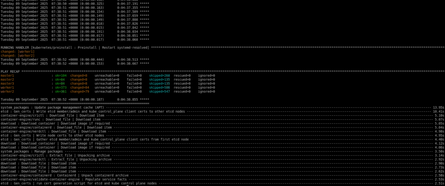
To follow the progress of DPU provisioning, run the following command to check its current phase:
Jump Node Console
            $ watch -n10 "kubectl describe dpu -n dpf-operator-system | grep 'Node Name\|Type\|Last\|Phase'"

  Dpu Node Name:                                       worker1
    Type:     InternalIP
    Type:     Hostname
    Last Transition Time:  2025-09-09T12:54:57Z
    Type:                  Initialized
    Last Transition Time:  2025-09-09T12:54:57Z
    Type:                  BFBReady
    Last Transition Time:  2025-09-09T12:55:17Z
    Type:                  NodeEffectReady
    Last Transition Time:  2025-09-09T12:55:19Z
    Type:                  InterfaceInitialized
    Last Transition Time:  2025-09-09T12:55:20Z
    Type:                  FWConfigured
    Last Transition Time:  2025-09-09T13:04:14Z
    Type:                  OSInstalled
    Last Transition Time:  2025-09-09T13:04:15Z
    Type:                  CheckedHostRebootNeed
    Last Transition Time:  2025-09-09T13:09:51Z
    Type:                  Rebooted
    Last Transition Time:  2025-09-09T13:10:51Z
    Type:                  HostNetworkReady
    Last Transition Time:  2025-09-09T13:11:01Z
    Type:                  DPUClusterReady
    Last Transition Time:  2025-09-09T13:11:02Z
    Type:                  Ready
  Phase:  Ready
  Dpu Node Name:                                       worker2
    Type:     InternalIP
    Type:     Hostname
    Last Transition Time:  2025-09-09T12:51:35Z
    Type:                  Initialized
    Last Transition Time:  2025-09-09T12:51:35Z
    Type:                  BFBReady
    Last Transition Time:  2025-09-09T12:51:51Z
    Type:                  NodeEffectReady
    Last Transition Time:  2025-09-09T12:51:52Z
    Type:                  InterfaceInitialized
    Last Transition Time:  2025-09-09T12:51:55Z
    Type:                  FWConfigured
    Last Transition Time:  2025-09-09T13:00:47Z
    Type:                  OSInstalled
    Last Transition Time:  2025-09-09T13:00:47Z
    Type:                  CheckedHostRebootNeed
    Last Transition Time:  2025-09-09T13:06:32Z
    Type:                  Rebooted
    Last Transition Time:  2025-09-09T13:07:32Z
    Type:                  HostNetworkReady
    Last Transition Time:  2025-09-09T13:07:42Z
    Type:                  DPUClusterReady
    Last Transition Time:  2025-09-09T13:07:42Z
    Type:                  Ready
  Phase:  Ready
Once it arrives at the "Ready" phase on both DPUs, validate that the DPUs have been provisioned successfully:
Jump Node Console
            $ kubectl wait --for=condition=ready --namespace dpf-operator-system dpu --all
dpu.provisioning.dpu.nvidia.com/worker1-mt2404xz0c98 condition met
dpu.provisioning.dpu.nvidia.com/worker2-mt2333xz0xq3 condition met
Ensure that the following DaemonSets have 2 ready replicas:
Jump Node Console
            $ kubectl wait ds --for=jsonpath='{.status.numberReady}'=2 --namespace nvidia-network-operator kube-multus-ds sriov-network-config-daemon sriov-device-plugin
daemonset.apps/kube-multus-ds condition met
daemonset.apps/sriov-network-config-daemon condition met
daemonset.apps/sriov-device-plugin condition met
Check that all the pods in the kube-system namespace are now ready:
Jump Node Console
            $ kubectl wait --for=condition=ready --namespace kube-system pods --all
pod/coredns-d665d669-lrz4s condition met
pod/coredns-d665d669-v2pzg condition met
pod/dns-autoscaler-79f85f486f-mh5p5 condition met
pod/kube-apiserver-master1 condition met
pod/kube-apiserver-master2 condition met
pod/kube-apiserver-master3 condition met
pod/kube-controller-manager-master1 condition met
pod/kube-controller-manager-master2 condition met
pod/kube-controller-manager-master3 condition met
pod/kube-flannel-fgknz condition met
pod/kube-flannel-p9zxr condition met
pod/kube-flannel-vjkrn condition met
pod/kube-flannel-wnfdr condition met
pod/kube-flannel-zktgn condition met
pod/kube-proxy-5ll4x condition met
pod/kube-proxy-k5m5w condition met
pod/kube-proxy-nn6mx condition met
pod/kube-proxy-srk6w condition met
pod/kube-proxy-t8mgs condition met
pod/kube-scheduler-master1 condition met
pod/kube-scheduler-master2 condition met
pod/kube-scheduler-master3 condition met
pod/kube-vip-master1 condition met
pod/kube-vip-master2 condition met
pod/kube-vip-master3 condition met
Finally, validate that all DPUServices, DPUServiceIPAMs, DPUServiceInterfaces and DPUServiceChains objects are now in the Ready state:
Jump Node Console
            $ kubectl get dpuservices -A | grep doca-hbn
dpf-operator-system   doca-hbn-clm7b                  True    Success   42m

$ kubectl wait --for=condition=DPUIPAMObjectReady --namespace dpf-operator-system dpuserviceipam --all
dpuserviceipam.svc.dpu.nvidia.com/loopback condition met
dpuserviceipam.svc.dpu.nvidia.com/pool1 condition met
dpuserviceipam.svc.dpu.nvidia.com/pool2 condition met

$ kubectl wait --for=condition=ServiceInterfaceSetReady --namespace dpf-operator-system dpuserviceinterface --all
dpuserviceinterface.svc.dpu.nvidia.com/doca-hbn-p0-if-xgrcl condition met
dpuserviceinterface.svc.dpu.nvidia.com/doca-hbn-p1-if-hpcbz condition met
dpuserviceinterface.svc.dpu.nvidia.com/doca-hbn-pf0vf10-if-52jnw condition met
dpuserviceinterface.svc.dpu.nvidia.com/doca-hbn-pf1vf10-if-4djh6 condition met
dpuserviceinterface.svc.dpu.nvidia.com/p0 condition met
dpuserviceinterface.svc.dpu.nvidia.com/p1 condition met
dpuserviceinterface.svc.dpu.nvidia.com/pf0vf10-rep condition met
dpuserviceinterface.svc.dpu.nvidia.com/pf1vf10-rep condition met

$ kubectl wait --for=condition=ServiceChainSetReady --namespace dpf-operator-system dpuservicechain --all
dpuservicechain.svc.dpu.nvidia.com/hbn-only-ljcqz condition met
Congratulations, the DPF system has been successfully installed!
Infrastructure Latency & Bandwidth Validation
Verify the deployment and that you can reach link-speed performance and good latency results on the DPF system by using various tests:
- RDMA - for latency measurements
- Iperf TCP - for bandwidth measurements
Each of the tests is described thoroughly. At the end of each test, you'll see the achieved performance.
Make sure that the servers are tuned for maximum performance (not covered in this document).
Performance Tests
RoCE Latency Test
Create Network Attachment Definitions (NADs) and test deployments using the following YAML files to create 4 pods running across two different worker nodes.
Each of these pods will have the host virtual function number 10 (VF10) device inserted into them using the hostdev plugin - one from PF0 and one from PF1 .
This deployment demonstrates that on each node, pods are isolated and connected to different networks over different VNIs.
We will show that:
- We can communicate and achieve accelerated traffic between pods running on different worker nodes but on the same network (performance testing)
- We can't communicate between pods connected to differenet networks (isolation test).
Below is the yaml file used for creating the NADs. Replace <PF0_VF_DEVICE> and <PF1_VF_DEVICE> with the correct device names on your worker node (e.g. ens5f0v10 and ens5f1v10):
nad-hostdev.yaml
            apiVersion: "k8s.cni.cncf.io/v1"
kind: NetworkAttachmentDefinition
metadata:
  name: hostdev-pf0vf10-worker1
spec:
  config: '{
    "cniVersion": "0.3.1",
    "name": "hostpf0vf10",
    "type": "host-device",
    "device": "<PF0_VF_DEVICE>",
    "ipam": {
        "type": "static",
        "addresses": [
          {
            "address": "10.0.121.1/29"
          }
        ],
        "routes": [
          {
            "dst": "10.0.121.8/29",
            "gw": "10.0.121.2"
          }
        ]
    }
  }'
---
apiVersion: "k8s.cni.cncf.io/v1"
kind: NetworkAttachmentDefinition
metadata:
  name: hostdev-pf1vf10-worker1
spec:
  config: '{
    "cniVersion": "0.3.1",
    "name": "hostpf1vf10",
    "type": "host-device",
    "device": "<PF1_VF_DEVICE>",
    "ipam": {
        "type": "static",
        "addresses": [
          {
            "address": "10.0.122.1/29"
          }
        ],
        "routes": [
          {
            "dst": "10.0.122.8/29",
            "gw": "10.0.122.2"
          }
        ]
    }
  }'
---
apiVersion: "k8s.cni.cncf.io/v1"
kind: NetworkAttachmentDefinition
metadata:
  name: hostdev-pf0vf10-worker2
spec:
  config: '{
    "cniVersion": "0.3.1",
    "name": "hostpf0vf10",
    "type": "host-device",
    "device": "<PF0_VF_DEVICE>",
    "ipam": {
        "type": "static",
        "addresses": [
          {
            "address": "10.0.121.9/29"
          }
        ],
        "routes": [
          {
            "dst": "10.0.121.0/29",
            "gw": "10.0.121.10"
          }
        ]
    }
  }'
---
apiVersion: "k8s.cni.cncf.io/v1"
kind: NetworkAttachmentDefinition
metadata:
  name: hostdev-pf1vf10-worker2
spec:
  config: '{
    "cniVersion": "0.3.1",
    "name": "hostpf1vf10",
    "type": "host-device",
    "device": "<PF1_VF_DEVICE>",
    "ipam": {
        "type": "static",
        "addresses": [
          {
            "address": "10.0.122.9/29"
          }
        ],
        "routes": [
          {
            "dst": "10.0.122.0/29",
            "gw": "10.0.122.10"
          }
        ]
    }
  }'
This is the YAML file used to create the deployments for PF0 (RED network). Replace <IMAGE_URL> with a relevant container image URL (The container image must include NVIDIA user space drivers and the perftest and iperf3 packages) :
testapp-performance-test-deployment-pf0.yaml
            apiVersion: apps/v1
kind: Deployment
metadata:
  name: sriov-hostdev-pf0vf10-test-worker1
  labels:
    app: sriov-hostdev-pf0vf10-test-worker1
spec:
  replicas: 1
  selector:
    matchLabels:
      app: sriov-hostdev-pf0vf10-test-worker1
  template:
    metadata:
      labels:
        app: sriov-hostdev-pf0vf10-test-worker1
      annotations:
        k8s.v1.cni.cncf.io/networks: hostdev-pf0vf10-worker1
    spec:
      topologySpreadConstraints:
      - maxSkew: 1
        topologyKey: kubernetes.io/hostname
        whenUnsatisfiable: DoNotSchedule
        labelSelector:
          matchLabels:
            app: sriov-test-worker
      nodeSelector:
        feature.node.kubernetes.io/dpu-enabled: "true"
        kubernetes.io/hostname: "worker1"
      containers:
      - name: testapp
        securityContext:
          privileged: true
          capabilities:
            add:
            - NET_ADMIN
            - IPC_LOCK
        image: <IMAGE_URL>
        command: ["sleep", "infinity"]
        ports:
        - containerPort: 5000
          name: tcp-server
        resources:
          requests:
            cpu: 24
            memory: 6Gi
          limits:
            cpu: 24
            memory: 6Gi
---
apiVersion: apps/v1
kind: Deployment
metadata:
  name: sriov-hostdev-pf0vf10-test-worker2
  labels:
    app: sriov-hostdev-pf0vf10-test-worker2
spec:
  replicas: 1
  selector:
    matchLabels:
      app: sriov-hostdev-pf0vf10-test-worker2
  template:
    metadata:
      labels:
        app: sriov-hostdev-pf0vf10-test-worker2
      annotations:
        k8s.v1.cni.cncf.io/networks: hostdev-pf0vf10-worker2
    spec:
      topologySpreadConstraints:
      - maxSkew: 1
        topologyKey: kubernetes.io/hostname
        whenUnsatisfiable: DoNotSchedule
        labelSelector:
          matchLabels:
            app: sriov-test-worker
      nodeSelector:
        feature.node.kubernetes.io/dpu-enabled: "true"
        kubernetes.io/hostname: "worker2"
      containers:
      - name: testapp
        securityContext:
          privileged: true
          capabilities:
            add:
            - NET_ADMIN
            - IPC_LOCK
        image: <IMAGE_URL>
        command: ["sleep", "infinity"]
        ports:
        - containerPort: 5000
          name: tcp-server
        resources:
          requests:
            cpu: 24
            memory: 6Gi
          limits:
            cpu: 24
            memory: 6Gi
Apply the following resources:
Jump Node Console
            $ kubectl apply -f nad-hostdev.yaml

$ kubectl apply -f testapp-performance-test-deployment-pf0.yaml
Validate that the deployment is running successfully:
Jump Node Console
            $ kubectl get pods -o wide
NAME                                              READY   STATUS    RESTARTS   AGE    IP              NODE      NOMINATED NODE   READINESS GATES
sriov-hostdev-pf0-test-worker1-76bbff86d-4gvsb    1/1     Running   0          3d1h   10.233.69.102   worker1   <none>           <none>
sriov-hostdev-pf0-test-worker2-649f58574c-5xrgw   1/1     Running   0          3d1h   10.233.70.177   worker2   <none>           <none>
Now that the test deployment is running, perform a latency performance test between two pods.
Connect to one of the pods in the deployment, specifically the pod running on the PF0 network on the first worker node:
Jump Node Console
$ kubectl exec -it sriov-hostdev-pf0-test-worker1-76bbff86d-4gvsb -- bash
From within the container, set an MTU value of 9000 and check the IP address on the net1 interface. Also identify the relevant RDMA device:
First Pod Console
            root@sriov-hostdev-pf0-test-worker1-76bbff86d-4gvsb:/# ip link set net1 mtu 9000

root@sriov-hostdev-pf0-test-worker1-76bbff86d-4gvsb:/# ip a
1: lo: <LOOPBACK,UP,LOWER_UP> mtu 65536 qdisc noqueue state UNKNOWN group default qlen 1000
    link/loopback 00:00:00:00:00:00 brd 00:00:00:00:00:00
    inet 127.0.0.1/8 scope host lo
       valid_lft forever preferred_lft forever
    inet6 ::1/128 scope host
       valid_lft forever preferred_lft forever
2: eth0@if185: <BROADCAST,MULTICAST,UP,LOWER_UP> mtu 1450 qdisc noqueue state UP group default
    link/ether 8a:d6:45:6a:b4:3d brd ff:ff:ff:ff:ff:ff link-netnsid 0
    inet 10.233.67.39/24 brd 10.233.67.255 scope global eth0
       valid_lft forever preferred_lft forever
    inet6 fe80::88d6:45ff:fe6a:b43d/64 scope link
       valid_lft forever preferred_lft forever
59: net1: <BROADCAST,MULTICAST,UP,LOWER_UP> mtu 9000 qdisc mq state UP group default qlen 1000
    link/ether 0e:a4:2e:4e:1f:9f brd ff:ff:ff:ff:ff:ff
    altname enp134s0f0v10
    inet 10.0.121.1/29 brd 10.0.121.7 scope global net1
       valid_lft forever preferred_lft forever
    inet6 fe80::ca4:2eff:fe4e:1f9f/64 scope link
       valid_lft forever preferred_lft forever

root@testapp-performance-6c69b69d9b-24gpj:/# rdma link | grep net1
link mlx5_12/1 state ACTIVE physical_state LINK_UP netdev net1
Start the ib_read_lat
server side:
First Pod Console
            root@sriov-hostdev-pf0-test-worker1-76bbff86d-4gvsb:/# ib_read_lat -F -n 20000 -d mlx5_12

************************************
* Waiting for client to connect... *
************************************
Using another console window , reconnect to the jump node and connect to a second pod running on the same network (PF0), on the second worker node.
Jump Node Console
$ kubectl exec -it sriov-hostdev-pf0-test-worker2-649f58574c-5xrgw -- bash
From within the container, set an MTU value of 9000 on the net1 interface, then identify the relevant RDMA Device and start the
ib_read_lat
client using the IP address from the server-side container, finally let's check the latency results:
First Pod Console
            root@sriov-hostdev-pf0-test-worker2-649f58574c-5xrgw:/# ip link set net1 mtu 9000

root@sriov-hostdev-pf0-test-worker2-649f58574c-5xrgw:/# rdma link | grep net1
link mlx5_12/1 state ACTIVE physical_state LINK_UP netdev net1

root@testapp-performance-6c69b69d9b-mrg4g:/# ib_read_lat -F -n 20000 -d mlx5_12 10.0.121.1
---------------------------------------------------------------------------------------
                    RDMA_Read Latency Test
 Dual-port       : OFF          Device         : mlx5_12
 Number of qps   : 1            Transport type : IB
 Connection type : RC           Using SRQ      : OFF
 PCIe relax order: ON
 ibv_wr* API     : ON
 TX depth        : 1
 Mtu             : 4096[B]
 Link type       : Ethernet
 GID index       : 3
 Outstand reads  : 16
 rdma_cm QPs     : OFF
 Data ex. method : Ethernet
---------------------------------------------------------------------------------------
 local address: LID 0000 QPN 0x04b9 PSN 0x4f96f3 OUT 0x10 RKey 0x078507 VAddr 0x006344ee3b0000
 GID: 00:00:00:00:00:00:00:00:00:00:255:255:10:00:121:09
 remote address: LID 0000 QPN 0x04b9 PSN 0x7fc74c OUT 0x10 RKey 0x07b607 VAddr 0x005a042c76c000
 GID: 00:00:00:00:00:00:00:00:00:00:255:255:10:00:121:01
---------------------------------------------------------------------------------------
 #bytes #iterations    t_min[usec]    t_max[usec]  t_typical[usec]    t_avg[usec]    t_stdev[usec]   99% percentile[usec]   99.9% percentile[usec]
 2       20000          3.99           166.68       4.12               8.26             9.08            44.07                   58.11
---------------------------------------------------------------------------------------
iPerf TCP Bandwidth Test
Connect to the first pods:
Jump Node Console
$ kubectl exec -it sriov-hostdev-pf0-test-worker1-76bbff86d-4gvsb -- bash
Before starting the
iperf3
server listeners, and to achieve good results, check which cores the pod is currently running on in another tab:
Jump Node Console
            $ ssh worker1
depuser@worker1:~$ sudo -i
root@worker1:~# crictl ps | grep testapp
68fe4bc7f6854       25a2fe7e1cbce       3 hours ago          Running             testapp                 0                   4fa7100bee05e       sriov-hostdev-pf0-test-worker1-76bbff86d-4gvsb

root@worker2:~# crictl inspect 68fe4bc7f6854 | jq '.status.resources.linux.cpusetCpus'
"28-51"
Use the following script to start multiple
iperf3
servers (1 for each core) on different ports:
iperf_server.sh
            #!/bin/bash

# Cores to bind the iperf3 server processes to
CORES=$1

# Calculate the first_core and last_core to provide the CPU range
first_core=$(echo $CORES | cut -d "-" -f1)
last_core=$(echo $CORES | cut -d "-" -f2)
ports_num=$(($last_core - $first_core + 1))

# Loop over the ports (5201 + i*2) for i in the given CPU range and run iperf3 servers
for i in $(seq 1 $ports_num); do
   echo "Running iperf3 server $i"
   taskset -c $(($i + $first_core - 1)) iperf3 -s -p $((5201 + i * 2)) > /dev/null 2>&1 &
done
Start the script using the previous CPU range (leave 1 core as a buffer):
First Pod Console
            root@sriov-hostdev-pf0-test-worker1-76bbff86d-4gvsb:/# chmod +x iperf_server.sh
root@sriov-hostdev-pf0-test-worker1-76bbff86d-4gvsb:/# ./iperf_server.sh 28-51
Running iperf3 server 1
Running iperf3 server 2

...
...
Running iperf3 server 23
Running iperf3 server 24

root@sriov-hostdev-pf0-test-worker1-76bbff86d-4gvsb:/# ps -ef | grep iperf3
root        2136       1  0 15:54 pts/2    00:00:00 iperf3 -s -p 5257
root        2137       1  0 15:54 pts/2    00:00:00 iperf3 -s -p 5259
...
...
root        2157       1  0 15:54 pts/2    00:00:00 iperf3 -s -p 5303
root        2158       1  0 15:54 pts/2    00:00:00 iperf3 -s -p 5305
Connect to the second pod:
Jump Node Console
$ kubectl exec -it sriov-hostdev-pf0-test-worker2-649f58574c-5xrgw -- bash
Follow the previously displayed method to identify the CPU cores that the second pod is running on.
Use the following script to start multiple
iperf3
clients that will connect to each
iperf3
server in the first pod:
The script receives 3 parameters: the server IP to connect to, the CPU cores on which to spawn the
iperf3processes, and the duration theiperf3test. Make sure to provide all 3 when initiating the script and providing the CPU cores as a range (28-51).Ensure that
jqandbcare installed on the pod for the script to run properly.
iperf_client.sh
            #!/bin/bash

# IP address of the server where iperf3 servers are running
SERVER_IP=$1  # Change to your server's IP

# Cores to bind the iperf3 client processes to
CORES=$2

# Duration to run the iperf3 test
DUR=$3

# Variable to accumulate the total bandwidth in Gbit/sec
total_bandwidth_Gbit=0

# Calculate the first_core and last_core to provide the CPU range
first_core=$(echo $CORES | cut -d "-" -f1)
last_core=$(echo $CORES | cut -d "-" -f2)
ports_num=$(($last_core - $first_core + 1))

# Array to store the PIDs of background tasks
pids=()

# Loop over the ports (5201 + i*2) for i in the given CPU range
for i in $(seq 1 $ports_num); do
    port=$((5201 + i * 2))
    cpu_core=$(($i + $first_core - 1))  # Assign CPU core based on the value of i
    output_file="iperf3_client_results_$port.log"

    # Run the iperf3 client in the background with CPU core binding
    timeout $(( DUR +5 )) taskset -c $cpu_core iperf3 -c $SERVER_IP -p $port -t $DUR -J > $output_file &
    pid=$!
    pids+=("$pid")
done

# Wait for all background tasks to complete and check their status
for pid in "${pids[@]}"; do
    wait $pid
    if [[ $? -ne 0 ]]; then
        echo "Process with PID $pid failed or timed out."
    fi
done

# Summarize the results from each log file
echo "Summary of iperf3 client results:"
for i in $(seq 1 $ports_num); do
    port=$((5201 + i * 2))
    output_file="iperf3_client_results_$port.log"

    if [[ -f $output_file ]]; then
        echo "Results for port $port:"

        # Parse the results and print a summary
        bandwidth_bps=$(jq '.end.sum_received.bits_per_second' $output_file)

        if [[ -n $bandwidth_bps ]]; then
           # Convert bandwidth from bps to Gbit/sec
           bandwidth_Gbit=$(echo "scale=3; $bandwidth_bps / 1000000000" | bc)
           echo "  Bandwidth: $bandwidth_Gbit Gbit/sec"

           # Accumulate the bandwidth for the total summary
           total_bandwidth_Gbit=$(echo "scale=3; $total_bandwidth_Gbit + $bandwidth_Gbit" | bc)

           # Delete current log file
           rm $output_file
        else
           echo "No bandwidth data found in $output_file"
        fi

    else
        echo "No results found for port $port"
    fi
done

# Print the total bandwidth summary
echo "Total Bandwidth across all streams: $total_bandwidth_Gbit Gbit/sec"
Run the script and check the performance results:
Second Pod Console
            root@sriov-hostdev-pf0-test-worker2-649f58574c-5xrgw:/# chmod +x iperf_client.sh

root@sriov-hostdev-pf0-test-worker2-649f58574c-5xrgw:/# ./iperf_client.sh 10.0.121.1 28-51 30

Summary of iperf3 client results:
Results for port 5203:
  Bandwidth: 14.207 Gbit/sec
Results for port 5205:
  Bandwidth: 22.445 Gbit/sec
Results for port 5207:
  Bandwidth: 8.868 Gbit/sec
Results for port 5209:
  Bandwidth: 11.115 Gbit/sec
Results for port 5211:
  Bandwidth: 14.104 Gbit/sec
Results for port 5213:
  Bandwidth: 13.387 Gbit/sec
Results for port 5215:
  Bandwidth: 22.743 Gbit/sec
Results for port 5217:
  Bandwidth: 12.132 Gbit/sec
Results for port 5219:
  Bandwidth: 13.927 Gbit/sec
Results for port 5221:
  Bandwidth: 13.470 Gbit/sec
Results for port 5223:
  Bandwidth: 22.720 Gbit/sec
Results for port 5225:
  Bandwidth: 14.771 Gbit/sec
Results for port 5227:
  Bandwidth: 12.752 Gbit/sec
Results for port 5229:
  Bandwidth: 9.174 Gbit/sec
Results for port 5231:
  Bandwidth: 14.265 Gbit/sec
Results for port 5233:
  Bandwidth: 24.338 Gbit/sec
Results for port 5235:
  Bandwidth: 14.087 Gbit/sec
Results for port 5237:
  Bandwidth: 13.353 Gbit/sec
Results for port 5239:
  Bandwidth: 14.555 Gbit/sec
Results for port 5241:
  Bandwidth: 20.808 Gbit/sec
Results for port 5243:
  Bandwidth: 13.056 Gbit/sec
Results for port 5245:
  Bandwidth: 16.648 Gbit/sec
Results for port 5247:
  Bandwidth: 17.545 Gbit/sec
Results for port 5249:
  Bandwidth: 20.905 Gbit/sec
Total Bandwidth across all streams: 375.375 Gbit/sec
Network Isolation Test
Finally, verify that the two pods running on different networks (using virtual functions on PF0 and PF1) can't communicate with each other.
Apply the following YAML to create the deployments for PF1 (BLUE network) - Make sure to replace <IMAGE_URL> with a relevant container image URL:
testapp-performance-test-deployment-pf1.yaml
            apiVersion: apps/v1
kind: Deployment
metadata:
  name: sriov-hostdev-pf1vf10-test-worker1
  labels:
    app: sriov-hostdev-pf1vf10-test-worker1
spec:
  replicas: 1
  selector:
    matchLabels:
      app: sriov-hostdev-pf1vf10-test-worker1
  template:
    metadata:
      labels:
        app: sriov-hostdev-pf1vf10-test-worker1
      annotations:
        k8s.v1.cni.cncf.io/networks: hostdev-pf1vf10-worker1
    spec:
      topologySpreadConstraints:
      - maxSkew: 1
        topologyKey: kubernetes.io/hostname
        whenUnsatisfiable: DoNotSchedule
        labelSelector:
          matchLabels:
            app: sriov-test-worker
      nodeSelector:
        feature.node.kubernetes.io/dpu-enabled: "true"
        kubernetes.io/hostname: "worker1"
      containers:
      - name: testapp
        securityContext:
          privileged: true
          capabilities:
            add:
            - NET_ADMIN
            - IPC_LOCK
        image: <IMAGE_URL>
        command: ["sleep", "infinity"]
        ports:
        - containerPort: 5000
          name: tcp-server
        resources:
          requests:
            cpu: 24
            memory: 6Gi
          limits:
            cpu: 24
            memory: 6Gi
---
apiVersion: apps/v1
kind: Deployment
metadata:
  name: sriov-hostdev-pf1vf10-test-worker2
  labels:
    app: sriov-hostdev-pf1vf10-test-worker2
spec:
  replicas: 1
  selector:
    matchLabels:
      app: sriov-hostdev-pf1vf10-test-worker2
  template:
    metadata:
      labels:
        app: sriov-hostdev-pf1vf10-test-worker2
      annotations:
        k8s.v1.cni.cncf.io/networks: hostdev-pf1vf10-worker2
    spec:
      topologySpreadConstraints:
      - maxSkew: 1
        topologyKey: kubernetes.io/hostname
        whenUnsatisfiable: DoNotSchedule
        labelSelector:
          matchLabels:
            app: sriov-test-worker
      nodeSelector:
        feature.node.kubernetes.io/dpu-enabled: "true"
        kubernetes.io/hostname: "worker2"
      containers:
      - name: testapp
        securityContext:
          privileged: true
          capabilities:
            add:
            - NET_ADMIN
            - IPC_LOCK
        image: <IMAGE_URL>
        command: ["sleep", "infinity"]
        ports:
        - containerPort: 5000
          name: tcp-server
        resources:
          requests:
            cpu: 24
            memory: 6Gi
          limits:
            cpu: 24
            memory: 6Gi
Jump Node Console
            $ kubectl apply -f testapp-performance-test-deployment-pf1.yaml

$ kubectl get pods -o wide
NAME                                              READY   STATUS    RESTARTS   AGE    IP              NODE      NOMINATED NODE   READINESS GATES
sriov-hostdev-pf0-test-worker1-76bbff86d-4gvsb    1/1     Running   0          3d1h   10.233.69.102   worker1   <none>           <none>
sriov-hostdev-pf0-test-worker2-649f58574c-5xrgw   1/1     Running   0          3d1h   10.233.70.177   worker2   <none>           <none>
sriov-hostdev-pf1-test-worker1-f9bc5f88f-msl4r    1/1     Running   0          3d1h   10.233.69.11    worker1   <none>           <none>
sriov-hostdev-pf1-test-worker2-f9bc5f88f-pqsb6    1/1     Running   0          3d1h   10.233.70.73    worker2   <none>           <none>
Connect to the pod running on the second worker node, with the PF1 network, add the required routing entry and try to ping the first pod running on the first worker node, with the PF0 network:
Jump Node Console
            $ kubectl exec -it sriov-hostdev-pf1-test-worker2-f9bc5f88f-pqsb6 -- bash

root@sriov-hostdev-pf1-test-worker2-f9bc5f88f-pqsb6:/# ip route add 10.0.121.0/29 via 10.0.122.2
root@sriov-hostdev-pf1-test-worker2-f9bc5f88f-pqsb6:/# ping 10.0.121.1
This ping operation should fail due to the network isolation implemented in HBN using different VLANs, VNIs and VRFs.
Authors

| Guy Zilberman Guy Zilberman is a solution architect at NVIDIA's Networking Solution s Labs, bringing extensive experience from several leadership roles in cloud computing. He specializes in designing and implementing solutions for cloud and containerized workloads, leveraging NVIDIA's advanced networking technologies. His work primarily focuses on open-source cloud infrastructure, with expertise in platforms such as Kubernetes (K8s) and OpenStack. |

| Shachar Dor Shachar Dor joined the Solutions Lab team after working more than ten years as a software architect at NVIDIA Networking (previously Mellanox Technologies), where he was responsible for the architecture of network management products and solutions. Shachar's focus is on networking technologies, especially around fabric bring-up, configuration, monitoring, and life-cycle management. Shachar has a strong background in software architecture, design, and programming through his work on multiple projects and technologies also prior to joining the company. |
NVIDIA and the NVIDIA logo, are trademarks and/or registered trademarks of NVIDIA Corporation in the U.S. and other countries. Other company and product names may be trademarks of the respective companies with which they are associated. TM
© 2025 NVIDIA Corporation. All rights reserved.
This document is provided for information purposes only and shall not be regarded as a warranty of a certain functionality, condition, or quality of a product. NVIDIA Corporation (“NVIDIA”) makes no representations or warranties, expressed or implied, as to the accuracy or completeness of the information contained in this document and assumes no responsibility for any errors contained herein. NVIDIA shall have no liability for the consequences or use of such information or for any infringement of patents or other rights of third parties that may result from its use. This document is not a commitment to develop, release, or deliver any Material (defined below), code, or functionality. NVIDIA reserves the right to make corrections, modifications, enhancements, improvements, and any other changes to this document, at any time without notice. Customer should obtain the latest relevant information before placing orders and should verify that such information is current and complete. NVIDIA products are sold subject to the NVIDIA standard terms and conditions of sale supplied at the time of order acknowledgement, unless otherwise agreed in an individual sales agreement signed by authorized representatives of NVIDIA and customer (“Terms of Sale”). NVIDIA hereby expressly objects to applying any customer general terms and conditions with regards to the purchase of the NVIDIA product referenced in this document. No contractual obligations are formed either directly or indirectly by this document.