Installation
Installation and initialization of the system require attention to the normal mechanical, power, and thermal precautions for rack-mounted equipment.
The rack mounting holes conform to the EIA-310 standard for 19-inch racks. Take precautions to guarantee proper ventilation in order to maintain good airflow at ambient temperature.
Unless otherwise specified, NVIDIA products are designed to work in an environmentally controlled data center with low levels of gaseous and dust (particulate) contamination.
The operation environment should meet severity level G1 as per ISA 71.04 for gaseous contamination and ISO 14644-1 class 8 for cleanliness level.
The installation procedure for the system involves the following phases:
Step | Procedure | See |
1 | Follow the safety warnings | |
2 | Pay attention to the air flow consideration within the system and rack | |
3 | Make sure that none of the package contents is missing or damaged | |
4 | Mount the system into a rack enclosure | |
5 | Power on the system | |
6 | Perform system bring-up | |
7 | [Optional] FRU replacements |
Prior to the installation, please review the Safety Warnings. Note that some warnings may not apply to all models.
The drawings are provided for illustration purposes only. The panel and modules design may vary depending on the system.
The SN2201_M systems are offered with Connector (front) side inlet to power side outlet airflow pattern.
The SN2201 systems are offered with two air flow patterns:
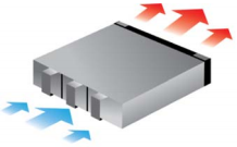
Power (rear) side inlet to connector side outlet - marked with blue power supplies/fans FRUs’ handles or blue dots that are placed on the power inlet side.
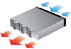
Connector (front) side inlet to power side outlet - marked with red power supplies/fans FRUs’ handles or red dots that are placed on the power inlet side.
Air Flow Direction Marking - Power Side Inlet to Connector Side Outlet 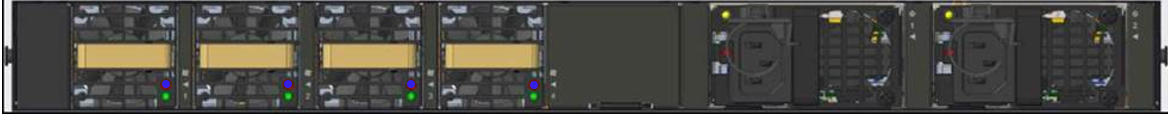
|
Air Flow Direction Marking - Connector Side Inlet to Power Side Outlet 
SN2201_M: 
|
All servers and systems in the same rack should be planned with the same airflow direction.
All FRU components need to have the same air flow direction. A mismatch in the air flow will affect the heat dissipation.
The table below provides an air flow color legend.
Direction | Description and OPN Designation |
| Connector side inlet to power side outlet. The airflow direction is indicated by red latches or by red dots that are placed on the power inlet side. |
| Power side inlet to connector side outlet. The airflow direction is indicated by blue latches or by blue dots that are placed on the power inlet side. |
Before installing your new system, unpack it and check against the parts list below that all the parts have been sent. Check the parts for visible damage that may have occurred during shipping.
The SN2201 systems package content is as follows:
1 – System
1 – Rail kit
1 – Power cable for each power supply unit – Type C13-C14
1 – DB9 to RJ-45 2m harness
1 - RJ-45 to RJ-45 2m harness
The SN2201_M systems package content is as follows:
1 – System
1 – Rail kit
1 – DB9 to RJ-45 2m harness
1 - RJ-45 to RJ-45 2m harness
If anything is damaged or missing, contact your sales representative at enterprisesupport@nvidia.com.
The systems are shipped with the rail-kits specified in the following table:
System Model | Rail Kit |
SN2201 | SN2201 Tool-Less Rail Kit |
SN2201_M | SN2201_M Tool-Less 4-Post Mounting Rail Kit |