Ethernet Network
Ethernet supported capabilities:
This feature allows packet burst handling, while avoiding packet drops that may occur when a large amount of packets is sent in a short period of time. For the feature’s registry keys, see section Performance Registry Keys.
By default, the feature is disabled, and the AsyncReceiveIndicate registry key is set to 0. To enable the feature, choose one of the following options:
To enable packet burst buffering using threaded DPC (recommended), set the AsyncReceiveIndicate registry key to 1.
To enable packet burst buffering using polling, set the AsyncReceiveIndicate to 2.
To control the number of reserved receive packets, set the RfdReservationFactor registry key:
|
Default |
150 |
|
Recommended |
10,000 |
|
Maximum |
5,000,000 |
The memory consumption will increase in accordance with the "RfdReservationFactor" registry key value.
This feature helps avoid dropping packets when the driver is not posting receive descriptors fast enough to the device (e.g. in cases of high CPU utilization).
Enabling/Disabling the Feature
There are two ways to enable/disable this feature:
Send down an OID to the driver. The following is the information buffer format:
            Typedef struct _DROPLESS_MODE
{
UINT32 signature; UINT8	dropless_mode;
} DROPLESS_MODE, *PDROPLESS_MODE;
OID code
0xFFA0C932
Signature value
(ULONG) 0x0C1EA2
Dropless_mode value
1- Enables the feature
2- Disables the featureThe driver sets a default timeout value of 5 milliseconds.
Add the "DelayDropTimeout" registry key, set the value to one of the following options, and reload the adapter:
DelayDropTimeout
“50" (recommended value to set the timeout to is 5 milliseconds)
"0" to disable Note: As of WinOF-2 v2.20, this key can be changed dynamically. In any case of an illegal input, the value will fall back to the default value and not to the last value used.
The registry key should be added to HKEY_LOCAL_MACHINE\SYSTEM\CurrentControlSet\Control\Class\{4d36e972-e325-11ce- bfc1-08002be10318}\<IndexValue>
To find the IndexValue, refer to section Finding the Index Value of the Network Interface.
Status Query
The status of the feature can be queried by sending down the same OID code (0xFFA0C932). If enabled, the driver will fill up the information buffer in the following format
            DROPLESS_MODE *answer = (DROPLESS_MODE *)InformationBuffer;
answer->signature = MLX_OID_BUFFER_SIGNATURE;
answer->dropless_mode = 1;
The Dropless_mode value will be set to 0 if disabled.
Timeout Values and Timeout Notification
The feature’s timeout values are defined as follows:
|
Registry value units |
100usec |
|
Default driver value |
50 (5 milliseconds) |
|
Accepted values |
0 (disabled) to100 (10 milliseconds) |
When the feature is enabled and a packet is received for an RQ with no receive WQEs, the packet processing is delayed, waiting for receive WQEs to be posted. The feature allows the flow control mechanism to take over, thus avoiding packet loss. During this period, the timer starts ticking, and if receive WQEs are not posted before the timer expires, the packet is dropped, and the feature is disabled.
The driver notifies of the timer’s expiration by generating an event log with event ID 75 and the following message:
"Delay drop timer timed out for RQ Index [RqId]. Dropless mode feature is now disabled".
The feature can be re-enabled by sending down an OID call again with a non-zero timeout value. Every time the feature is enabled by the user, the driver logs an event with event ID 77 and the following message:
"Dropless mode entered. For more details, please refer to the user manual document"
Similarly, every time the feature is disabled by the user, the driver logs an event with event ID 78 and the following message:
"Dropless mode exited. For more details, please refer to the user manual document."
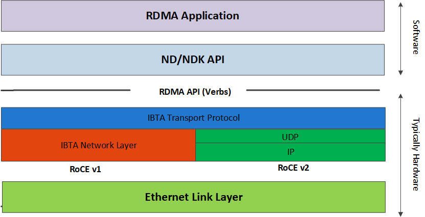
Remote Direct Memory Access (RDMA) is the remote memory management capability that allows server to server data movement directly between application memory without any CPU involvement. RDMA over Converged Ethernet (RoCE) is a mechanism to provide this efficient data transfer with very low latencies on lossless Ethernet networks. With advances in data center convergence over reliable Ethernet, ConnectX® EN with RoCE uses the proven and efficient RDMA transport to provide the platform for deploying RDMA technology in mainstream data center application at 10GigE and 40GigE link-speed. ConnectX® EN with its hardware offload support takes advantage of this efficient RDMA transport (InfiniBand) services over Ethernet to deliver ultra-low latency for performance-critical and transaction intensive applications such as financial, database, storage, and content delivery networks. RoCE encapsulates IB transport and GRH headers in Ethernet packets bearing a dedicated ether type. While the use of GRH is optional within InfiniBand subnets, it is mandatory when using RoCE. Applications written over IB verbs should work seamlessly, but they require provisioning of GRH information when creating address vectors. The library and driver are modified to provide mapping from GID to MAC addresses required by the hardware.
IP Routable (RoCEv2)
RoCE has two addressing modes: MAC based GIDs, and IP address based GIDs. In RoCE IP based, if the IP address changes while the system is running, the GID for the port will automatically be updated with the new IP address, using either IPv4 or IPv6.
RoCE IP based allows RoCE traffic between Windows and Linux systems, which use IP based GIDs by default.
A straightforward extension of the RoCE protocol enables traffic to operate in layer 3 environments. This capability is obtained via a simple modification of the RoCE packet format. Instead of the GRH used in RoCE, routable RoCE packets carry an IP header which allows traversal of IP L3 Routers and a UDP header that serves as a stateless encapsulation layer for the RDMA Transport Protocol Packets over IP.
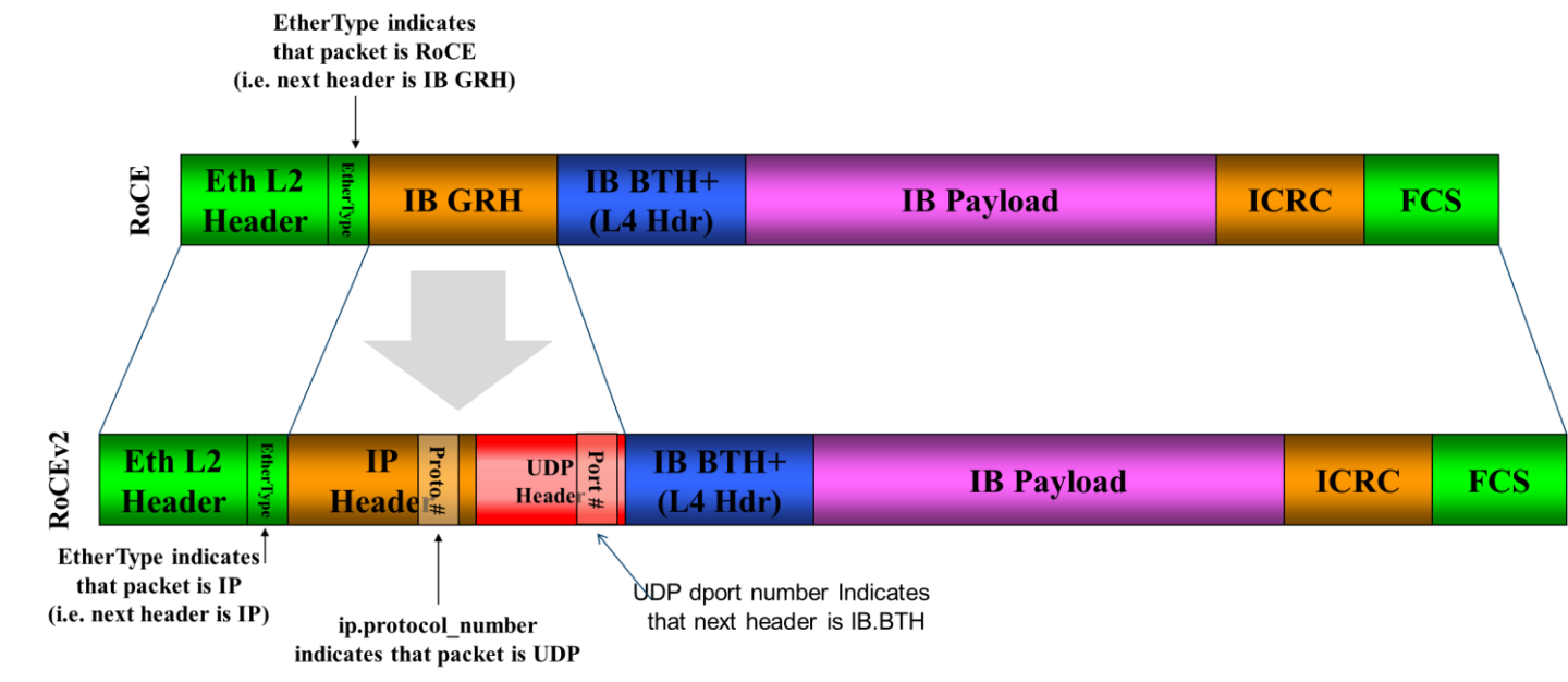
RoCE & RoCE v2 Differences
The proposed RoCEv2 packets use a well-known UDP destination port value that unequivocally distinguishes the datagram. Similar to other protocols that use UDP encapsulation, the UDP source port field is used to carry an opaque flow-identifier that allows network devices to implement packet forwarding optimizations (e.g. ECMP) while staying agnostic to the specifics of the protocol header format.
The UDP source port is calculated as follows: UDP.SrcPort = (SrcPort XOR DstPort) OR 0xC000 , where SrcPort and DstPort are the ports used to establish the connection.
For example, in a Network Direct application, when connecting to a remote peer, the destination IP address and the destination port must be provided as they are used in the calculation above. The source port provision is optional.
Furthermore, since this change exclusively affects the packet format on the wire, and due to the fact that with RDMA semantics packets are generated and consumed below the AP applications can seamlessly operate over any form of RDMA service (including the routable version of RoCE as shown in the RoCE and RoCE v2 Frame Format Differences diagram), in a completely transparent way (Standard RDMA APIs are IP based already for all existing RDMA technologies).
The fabric must use the same protocol stack in order for nodes to communicate.
In earlier versions, the default value of RoCE mode was RoCE v1. As of WinOF-2 v1.30, the default value of RoCE mode will be RoCEv2.
Upgrading from earlier versions to version 1.30 or above will save the old default value (RoCEv1).
RoCE Configuration
In order to function reliably, RoCE requires a form of flow control. While it is possible to use global flow control, this is normally undesirable, for performance reasons.
The normal and optimal way to use RoCE is to use Priority Flow Control (PFC). To use PFC, it must be enabled on all endpoints and switches in the flow path.
In the following section we present instructions to configure PFC on NVIDIA® ConnectX® family cards. There are multiple configuration steps required, all of which may be performed via PowerShell. Therefore, although we present each step individually, you may ultimately choose to write a PowerShell script to do them all in one step. Note that administrator privileges are required for these steps.
The NIC is configured by default to enable RoCE. If the switch is not configured to enable ECN and/or PFC, this will cause performance degradation. Thus, it is recommended to enable ECN on the switch or disable the *NetworkDirect registry key.
For more information on how to enable ECN and PFC on the switch, refer to the https://enterprise-support.nvidia.com/docs/DOC-2855 community page.
Configuring Windows Host
Since PFC is responsible for flow controlling at the granularity of traffic priority, it is necessary to assign different priorities to different types of network traffic.
As per RoCE configuration, all ND/NDK traffic is assigned to one or more chosen priorities, where PFC is enabled on those priorities.
Configuring Windows host requires configuring QoS. To configure QoS, please follow the procedure described in Configuring Quality of Service (QoS)
Global Pause (Flow Control)
To use Global Pause (Flow Control) mode, disable QoS and Priority:
            PS $ Disable-NetQosFlowControl
PS $ Disable-NetAdapterQos <interface name>
Go to: Device manager --> Network adapters --> Mellanox ConnectX-4/ConnectX-5 Ethernet Adapter --> Properties -->Advanced tab

Configuring Arista Switch
Set the ports that face the hosts as trunk.
(config)#
interfaceet10 (config-if-Et10)# switchport mode trunkSet VID allowed on trunk port to match the host VID.
(config-
if-Et10)# switchport trunk allowed vlan100Set the ports that face the network as trunk.
(config)#
interfaceet20 (config-if-Et20)# switchport mode trunkAssign the relevant ports to LAG.
(config)#
interfaceet10 (config-if-Et10)# dcbx mode ieee (config-if-Et10)# speed forced 40gfull (config-if-Et10)# channel-group11mode activeEnable PFC on ports that face the network.
(config)#
interfaceet20 (config-if-Et20)# load-interval5(config-if-Et20)# speed forced 40gfull (config-if-Et20)# switchport trunknativevlan tag (config-if-Et20)# switchport trunk allowed vlan11(config-if-Et20)# switchport mode trunk (config-if-Et20)# dcbx mode ieee (config-if-Et20)# priority-flow-control mode on (config-if-Et20)# priority-flow-control priority3no-drop
Using Global Pause (Flow Control)
            (config)# interface et10
(config-if-Et10)# flowcontrol receive on
(config-if-Et10)# flowcontrol send on
Using Priority Flow Control (PFC)
            (config)# interface et10
(config-if-Et10)# dcbx mode ieee
(config-if-Et10)# priority-flow-control mode on
(config-if-Et10)# priority-flow-control priority 3 no-drop
Configuring Router (PFC only)
The router uses L3's DSCP value to mark the egress traffic of L2 PCP. The required mapping, maps the three most significant bits of the DSCP into the PCP. This is the default behavior, and no additional configuration is required.
Copying Port Control Protocol (PCP) between Subnets
The captured PCP option from the Ethernet header of the incoming packet can be used to set the PCP bits on the outgoing Ethernet header.
Configuring the RoCE Mode
RoCE mode is configured per adapter or per driver. If RoCE mode key is set for the adapter, then it will be used. Otherwise, it will be configured by the per-driver key. The per-driver key is shared between all devices in the system.
The supported RoCE modes depend on the firmware installed. If the firmware does not support the needed mode, the fallback mode would be the maximum supported RoCE mode of the installed NIC.
RoCE is enabled by default. Configuring or disabling the RoCE mode can be done via the registry key.
To update it for a specific adapter using the registry key, set the roce_mode as follows:
Find the registry key index value of the adapter according to section Finding the Index Value of the Network Interface.
Set the roce_mode in the following path:
HKEY_LOCAL_MACHINE\SYSTEM\CurrentControlSet\Control\Class\{4d36e972-e325-11ce-bfc1-08002be10318}\<IndexValue>
HKEY_LOCAL_MACHINE\SYSTEM\CurrentControlSet\Services\mlx5\Parameters\Roce
For changes to take effect, please restart the network adapter after changing this registry key.
Registry Key Parameters
The following are per-driver and will apply to all available adapters.
|
Parameters Name |
Parameter type |
Description |
Allowed and Default Values |
|
roce_mode |
DWORD |
Sets the RoCE mode. The following are the possible RoCE modes:
|
|
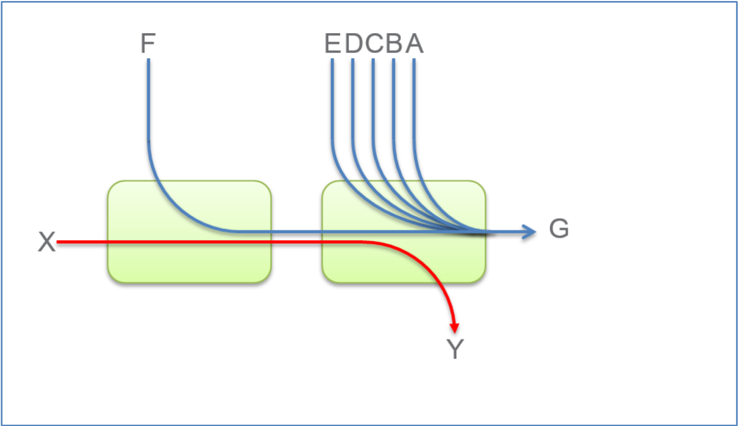
Network Congestion occurs when the number of packets being transmitted through the network approaches the packet handling the capacity of the network. A congested network will suffer from throughput deterioration manifested by increasing time delays and high latency.
In lossy environments, this leads to a packet loss. In lossless environments, it leads to “victim flows” (streams of data which are affected by the congestion, caused by other data flows that pass through the same network).
The figure below demonstrates a victim flow scenario. In the absence of congestion control, flow X'Y suffers from reduced bandwidth due to flow F'G, which experiences congestion. To address this, Congestion Control methods and protocols were defined.
This chapter describes (in High-Level), RoCEv2 Congestion Management (RCM), and provides a guide on how to configure it in Windows environment.
RoCEv2 Congestion Management (RCM) provides the capability to avoid congestion hot spots and optimize the throughput of the fabric.
With RCM, congestion in the fabric is reported back to the “sources” of traffic. The sources, in turn, react by throttling down their injection rates, thus preventing the negative effects of fabric buffer saturation and increased queuing delays.
For signaling of congestion, RCM relies on the mechanism defined in RFC3168, also known as DCQCN.
The source node and destination node can be considered as a “closed-loop control” system. Starting from the trigger, when the destination node reflects the congestion alert to the source node, the source node reacts by decreasing, and later on increasing, the Tx rates according to the feedback provided. The source node keeps increasing the Tx rates until the system reaches a steady state of non-congested flow with traffic as high rate as possible.
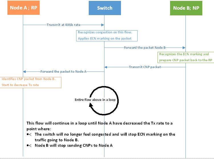
The RoCEv2 Congestion Management feature is composed of the following points:
Congestion Point (CP) - detects congestion and marks packets using the DCQCN bits
Notification Point (NP) (receiving end node) - reacts to the DCQCN marked packets by sending congestion notification packets (CNPs)
Reaction Point (RP) (transmitting end node) - reduces the transmission rate according to the received CNPs
These components can be seen in the High-Level sequence diagram below:
For further details, please refer to the IBTA RoCeV2 Spec, Annex A-17.
Restrictions and Limitations
|
Restrictions and Limitations |
|
|
General |
|
|
NVIDIA® |
|
RCM Configuration
RCM configuration to NVIDIA® adapter is done via mlx5cmd tool.
Mlx5Cmd.exe -Qosconfig -Dcqcn -Name <Network Adapter Name> -Get
Example of RCM being disabled:
            PS C:\Users\admin\Desktop> Mlx5Cmd.exe -Qosconfig -Dcqcn -Name "Ethernet" -Get
DCQCN RP attributes for adapter "EthernetcnRPEnablePrio0: 0
	DcqcnRPEnablePrio1: 0
	DcqcnRPEnablePrio2: 0
	DcqcnRPEnablePrio3: 0
	DcqcnRPEnablePrio4: 0
	DcqcnRPEnablePrio5: 0
	DcqcnRPEnablePrio6: 0
	DcqcnRPEnablePrio7: 0
	DcqcnClampTgtRate: 0
	DcqcnClampTgtRateAfterTimeInc: 1
	DcqcnRpgTimeReset: 100
	DcqcnRpgByteReset: 400
	DcqcnRpgThreshold: 5
	DcqcnRpgAiRate: 10
	DcqcnRpgHaiRate: 100
	DcqcnAlphaToRateShift: 11
	DcqcnRpgMinDecFac: 50
	DcqcnRpgMinRate: 1
	DcqcnRateToSetOnFirstCnp: 3000
	DcqcnDceTcpG: 32
	DcqcnDceTcpRtt: 4
	DcqcnRateReduceMonitorPeriod: 32
	DcqcnInitialAlphaValue: 0

DCQCN NP attributes for adapter "Ethernet":
	DcqcnNPEnablePrio0: 0
	DcqcnNPEnablePrio1: 0
	DcqcnNPEnablePrio2: 0
	DcqcnNPEnablePrio3: 0
	DcqcnNPEnablePrio4: 0
	DcqcnNPEnablePrio5: 0
	DcqcnNPEnablePrio6: 0
	DcqcnNPEnablePrio7: 0
    DcqcnCnpDscp: 0
	DcqcnCnp802pPrio: 7
	DcqcnCnpPrioMode: 1
The command was executed successfully
Mlx5Cmd.exe -Qosconfig -Dcqcn -Name <Network Adapter Name> -Enable/Disable
This can be used on all priorities or on a specific priority.
            PS C:\Users\admin\Desktop> Mlx5Cmd.exe -Qosconfig -Dcqcn -Name "Ethernet" -Enable

PS C:\Users\admin\Desktop> Mlx5Cmd.exe -Qosconfig -Dcqcn -Name "Ethernet" -Get
DCQCN RP attributes for adapter "Ethernet":
	DcqcnRPEnablePrio0: 1
	DcqcnRPEnablePrio1: 1
	DcqcnRPEnablePrio2: 1
	DcqcnRPEnablePrio3: 1
	DcqcnRPEnablePrio4: 1
	DcqcnRPEnablePrio5: 1
	DcqcnRPEnablePrio6: 1
	DcqcnRPEnablePrio7: 1
	DcqcnClampTgtRate: 0
	DcqcnClampTgtRateAfterTimeInc: 1
	DcqcnRpgTimeReset: 100
	DcqcnRpgByteReset: 400
	DcqcnRpgThreshold: 5
	DcqcnRpgAiRate: 10
	DcqcnRpgHaiRate: 100
	DcqcnAlphaToRateShift: 11
	DcqcnRpgMinDecFac: 50
	DcqcnRpgMinRate: 1
	DcqcnRateToSetOnFirstCnp: 3000
	DcqcnDceTcpG: 32
	DcqcnDceTcpRtt: 4
	DcqcnRateReduceMonitorPeriod: 32
	DcqcnInitialAlphaValue: 0

DCQCN NP attributes for adapter "Ethernet":
	DcqcnNPEnablePrio0: 1
	DcqcnNPEnablePrio1: 1
	DcqcnNPEnablePrio2: 1
	DcqcnNPEnablePrio3: 1
	DcqcnNPEnablePrio4: 1
	DcqcnNPEnablePrio5: 1
	DcqcnNPEnablePrio6: 1
	DcqcnNPEnablePrio7: 1
	DcqcnCnpDscp: 0
	DcqcnCnp802pPrio: 7
	DcqcnCnpPrioMode: 1
The command was executed successfully
RCM Parameters
The table below lists the parameters that can be configured, their description and allowed values.
|
Parameter (Type) |
Allowed Values |
|
DcqcnEnablePrio0 (BOOLEAN) |
0/1 |
|
DcqcnEnablePrio1 (BOOLEAN) |
0/1 |
|
DcqcnEnablePrio2 (BOOLEAN) |
0/1 |
|
DcqcnEnablePrio3 (BOOLEAN) |
0/1 |
|
DcqcnEnablePrio4 (BOOLEAN) |
0/1 |
|
DcqcnEnablePrio5 (BOOLEAN) |
0/1 |
|
DcqcnEnablePrio6 (BOOLEAN) |
0/1 |
|
DcqcnEnablePrio7 (BOOLEAN) |
0/1 |
|
DcqcnClampTgtRate (1 bit) |
0/1 |
|
DcqcnClampTgtRateAfterTimeInc (1 bit) |
0/1 |
|
DcqcnCnpDscp (6 bits) |
0 - 63 |
|
DcqcnCnp802pPrio (3 bits) |
0 - 7 |
|
DcqcnCnpPrioMode(1 bit) |
0/1 |
|
DcqcnRpgTimeReset (uint32) |
0 - 131071 [uSec] |
|
DcqcnRpgByteReset (uint32) |
0 - 32767 [64 bytes] |
|
DcqcnRpgThreshold (uint32) |
1 - 31 |
|
DcqcnRpgAiRate (uint32) |
1 - line rate [Mbit/sec] |
|
DcqcnRpgHaiRate (uint32) |
1 - line rate [Mbit/sec] |
|
DcqcnAlphaToRateShift (uint32) |
0 - 11 |
|
DcqcnRpgMinDecFac (uint32) |
0 - 100 |
|
DcqcnRpgMinRate (uint32) |
0 - line rate |
|
DcqcnRateToSetOnFirstCnp (uint32) |
0 - line rate [Mbit/sec] |
|
DcqcnDceTcpG (uint32) |
0 - 1023 (fixed point fraction of 1024) |
|
DcqcnDceTcpRtt (uint32) |
0 - 131071 [uSec] |
|
DcqcnRateReduceMonitorPeriod (uint32) |
0 - UINT32-1 [uSec] |
|
DcqcnInitialAlphaValue (uint32) |
0 - 1023 (fixed point fraction of 1024) |
An attempt to set a greater value than the parameter’s maximum "line rate" value (if exists), will fail. The maximum "line rate" value will be set instead.
RCM Default Parameters
Every parameter has a default value assigned to it. The default value was set for optimal congestion control by NVIDIA®. In order to view the default parameters on the adapter, run the following command:
Mlx5Cmd .exe -Qosconfig -Dcqcn -Name <Network Adapter Name> -Defaults
RCM with Untagged Traffic
Congestion control for untagged traffic is configured with the port default priority that is used for untagged frames.
The port default priority configuration is done via Mlx5Cmd tool.
|
Parameter (Type) |
Allowed and Default Values |
Note |
|
DefaultUntaggedPriority |
0 - 7 Default: 0 |
As of WinOF-2 v2.10, this key can be changed dynamically. In any case of an illegal input, the value will fall back to the default value and not to the last value used. |
Mlx5Cmd .exe -QoSConfig -DefaultUntaggedPriority -Name -Get
Mlx5Cmd .exe -QoSConfig -DefaultUntaggedPriority -Name -Set
Congestion Control Behavior when Changing the Parameters
Changing the values of the parameters may strongly affect the congestion control efficiency.
Please make sure you fully understand the parameter usage, value and expected results before changing its default value.
CNP Priority
|
Parameter |
Description |
|
fCnpDscp |
This parameter changes the priority value on IP level that can be set for CNPs. |
|
DcqcnCnpPrioMode |
If this parameter is set to '0', then use DcqcnCnp802pPrio as the priority value (802.1p) on the Ethernet header of generated CNPs. Otherwise, the priority value of CNPs will be taken from received packets that were marked as DCQCN packets. |
|
DcqcnCnp802pPrio |
This parameter changes the priority value (802.1p) on the Ethernet header of generated CNPs. Set DcqcnCnpPrioMode to '0' in order to use this priority value. |
alpha -”α” = Rate Reduction Factor
The device maintains an “alpha” value per QP. This alpha value estimates the current congestion severity in the fabric.
|
Parameter |
Description |
|
DcqcnInitialAlphaValue |
This parameter sets the initial value of alpha that should be used when receiving the first CNP for a flow (expressed in a fixed point fraction of 2^10). The value of alpha is updated once every DcqcnDceTcpRtt, regardless of the reception of a CNP. If a CNP is received during this time frame, alpha value will increase. If no CNP reception happens, alpha value will decrease. |
|
DcqcnDceTcpG/DcqcnDceTcpRtt |
These two parameters maintain alpha.
|
“RP” Decrease
Changing the DcqcnRateToSetOnFirstCnp parameter determines the Current Rate (CR) that will be set once the first CNP is received.
The rate is updated only once every DcqcnRateReduceMonitorPeriod microseconds (multiple CNPs received during this time frame will not affect the rate) by using the following two formulas:
Cr1(new) = (1- (α /(2^DcqcnAlphaToRateShift)) )*Cr(old)
Cr2(new) = Cr(old)/DcqcnRpgMinDecFac
The maximal reduced rate will be chosen from these two formulas.
The target rate will be updated to the previous current rate according to the behavior stated in section Increase on the “RP”.
|
Parameter |
Description |
|
DcqcnRpgMinDecFac |
This parameter defines the maximal ratio of decrease in a single step (Denominator: !zero. Please see formula above). |
|
DcqcnAlphaToRateShift |
This parameter defines the decrease rate for a given alpha (see formula above) |
|
DcqcnRpgMinRate |
In addition to the DcqcnRpgMinDecFac , the DcqcnRpgMinRate parameter defines the minimal rate value for the entire single flow. Note: Setting it to a line rate will disable Congestion Control. |
“RP” Increase
RP increases its sending rate using a timer and a byte counter. The byte counter increases rate for every DcqcnRpgByteResetx64 bytes (mark it as B), while the timer increases rate every DcqcnRpgTimeReset time units (mark it as T). Every successful increase due to bytes transmitted/time passing is counted in a variable called rpByteStage and rpTimeStage (respectively).
The DcqcnRpgThreshold parameter defines the number of successive increase iteration (mark it as Th). The increase flow is divided into 3 types of phases, which are actually states in the “RP Rate Control State Machine”. The transition between the steps is decided according to DcqcnRpgThreshold parameter.
Fast Recovery
If MAX (rpByteStage, rpTimeStage) < Th.
No change to Target Rate (Tr)Additive Increase
If MAX (rpByteStage, rpTimeStage) > Th. && MIN (rpByteStage, rpTimeStage) < Th.
DcqcnRpgAiRate value is used to increase TrHyper Additive Increase
If MAX (rpByteStage, rpTimeStage) > Th. && MIN (rpByteStage, rpTimeStage) > Th.
DcqcnRpgHaiRate value is used to increase Tr
For further details, please refer to 802.1Qau standard, sections 32.11-32.15.
|
Parameter |
Description |
|
DcqcnClampTgtRateAfterTimeInc |
When receiving a CNP, the target rate should be updated if the transmission rate was increased due to the timer, and not only due to the byte counter. |
|
DcqcnClampTgtRate |
If set, whenever a CNP is processed, the target rate is updated to be the current rate. |
NVIDIA® Commands and Examples
For a full description of Congestion Control commands please refer to section MlxCmd Utilities.
|
Set a value for one or more parameters: |
|
|
Command |
Mlx5Cmd.exe -Qosconfig -Dcqcn -Name <Network Adapter Name> -Set -Arg1 <value> -Arg2 <value> |
|
Example |
PS C:\Users\admin\Desktop> Mlx5Cmd .exe -Qosconfig -Dcqcn -Name "Ethernet" -Set -DcqcnClampTgtRate 1 -DcqcnCnpDscp 3 |
|
Enable/Disable DCQCN for a specific priority: |
|
|
Command |
Mlx5Cmd.exe -Qosconfig -Dcqcn -Name <Network Adapter Name> -Enable <prio> |
|
Example |
PS C:\Users\admin\Desktop> Mlx5Cmd .exe -Qosconfig -Dcqcn -Name "Ethernet" -Enable/Disable 3 |
|
Enable/Disable DCQCN for all priorities: |
|
|
Command |
Mlx5Cmd.exe -Qosconfig -Dcqcn -Name <Network Adapter Name> -Enable |
|
Example |
PS C:\Users\admin\Desktop> Mlx5Cmd .exe -Qosconfig -Dcqcn -Name "Ethernet" -Enable/Disable |
|
Set port default priority for a specific priority: |
|
|
Command |
Mlx5Cmd.exe -Qosconfig -DefaultUntaggedPriority -Name <Network Adapter Name> -Set <prio> |
|
Example |
PS C:\Users\admin\Desktop> Mlx5Cmd .exe -Qosconfig -DefaultUntaggedPriority -Name "Ethernet" -Set 3 |
|
Restore the default settings of DCQCN the are defined by NVIDIA®: |
|
|
Command |
Mlx5Cmd.exe -Dcqcn -Name <Network Adapter Name> -Restore |
|
Example |
PS C:\Users\admin\Desktop> Mlx5Cmd .exe -Dcqcn -Name "Ethernet" -Restore |
For information on the RCM counters, please refer to section WinOF-2 Congestion Control.
Enhanced Connection Establishment (ECE) is a new negotiation scheme introduced in IBTA v1.4 to exchange extra information about nodes capabilities and later negotiate them at the connection establishment phase. ECE is intended for RDMA connection, i.e., it works in ND and NDK connections.
This capability is supported in ConnectX-6 Dx and above adapter cards.
ECE is used by the driver by default if ECE is supported by the firmware. The feature is enabled/disabled by setting the "EceSupportEnabled".
The registry key should be added to HKEY_LOCAL_MACHINE\SYSTEM\CurrentControlSet\Control\Class\{4d36e972-e325-11cebfc1-08002be10318}\<IndexValue>
To find the IndexValue, refer to section Finding the Index Value of the Network Interface.
|
Value Name |
Value |
Description |
|
EceSupportEnabled |
0 - Disabled 1 - Enabled (Default) |
Enables/Disables ECE support in the driver. |
To check if the feature is supported by the firmware, run:
mlx5cmd -dbg -FwCaps -name "Ethernet 8" -Local | grep "ece "
This capability can be disabled by the NV configuration as well.
To check whether Selective Repeat algorithm is supported, run:
mlxconfig -d mt4125_pciconf0 | grep RDMA_SELECTIVE_REPEAT_EN
To enable ECE algorithm using the NV configuration:
            mlxconfig -d mt4125_pciconf0 -y s ROCE_CC_LEGACY_DCQCN=0
mlxconfig -d mt4125_pciconf0 -y s USER_PROGRAMMABLE_CC=1 RDMA_SELECTIVE_REPEAT_EN=1
To check the feature's status, run:
mlx5cmd -Features
The command prints information on ECE feature: either "Enabled", "Disabled" or "Reason". The "Reason" can be either the firmware does not support this capability or ECE is disabled using the registry key.
To check ECE's state in the existing ND/NDK connections, run:
            mlx5cmd -ndkstat –ece
mlx5cmd -ndstat -ece
ECE value is printed on every connection (at the end of the line).
Zero touch RoCE enables RoCE to operate on fabrics where no PFC nor ECN are configured. This makes RoCE configuration a breeze while still maintaining its superior high performance.
Zero touch RoCE enables:
Packet loss minimization by:
Developing a congestion handling mechanism which is better adjusted to a lossy environment
Moving more of the congestion handling mechanism to the hardware and to the dedicated microcode
Moderating traffic bursts by tuning of transmission window and slow restart of transmission
Protocol packet loss handling improvement by:
ConnectX-4: Repeating transmission from a lost segment of a IB retransmission protocol
ConnectX-5 and above: Improving the response to the packet loss by using hardware re-transmission
ConnectX-6 Dx: Using a proprietary selective repeat protocol
Facilities
Zero touch RoCE contains the following facilities, used to enable the above algorithms.
SlowStart: Start a re-transmission with low bandwidth and gradually increase it
AdpRetrans: Adjust re-transmission parameters according to network behavior
TxWindow: Automatic tuning of the transmission window size
The facilities can be independently enabled or disabled. The change is persistent, i.e. the configuration does not change after the driver restart. By default, all the facilities are enabled.
Restrictions and Limitations
Currently, Zero touch RoCE is supported only for the Ethernet ports, supporting RoCE
The required firmware versions are: 1x.25.xxxx and above.
ConnectX-4/ConnectX-4 Lx, supports only the following facilities: SlowStart and AdpRetrans
Configuring Zero touch RoCE
Zero touch RoCE is configured using the mlx5cmd tool.
To view the status of the Zero touch RoCE on the adapter.
Mlx5Cmd.exe -ZtRoce -Name <Network Adapter Name> -Get
The output below shows the current state, which is limited by the firmware capabilities and the last state set.
Current configuration
forAdapter'Ethernet': AdpRetrans Disabled TxWindow Disabled SlowStart Enabled
To view the firmware capabilities regarding Zero touch RoCE.
Mlx5Cmd.exe -ZtRoce -Name <Network Adapter Name> -Caps
The output below is characteristic to ConnectX-4 adapter cards where only two facilities are supported:
FW capabilities
forAdapter'Ethernet': AdpRetrans Enabled TxWindow Disabled SlowStart EnabledTo view the software default settings.
Mlx5Cmd.exe -ZtRoce -Name <Network Adapter Name> -Defaults
The output below shows Zero touch RoCE default settings.
Default configuration
forAdapter'Ethernet': AdpRetrans Enabled TxWindow Enabled SlowStart Enabled
Configuring Zero touch RoCE Facilities
The facilities states can be enabled or disabled using the following format:
Mlx5Cmd -ZtRoce -Name <Network Adapter Name> -Set [-AdpRetrans 0 | 1 ] [-TxWindow 0 | 1 ] [-SlowStart 0 | 1]
The example below shows how you can enable Slow Restart and Transmission Window facilities and disable the Adaptive Re-transmission.
Mlx5Cmd -ZtRoce -Name "Ethernet 3" -Set -AdpRetrans 0 -TxWindow 1 -SlowStart 1
To disable all the facilities.
Mlx5Cmd -ZtRoce -Name <Network Adapter Name> –Disable
To enable all the facilities.
Mlx5Cmd -ZtRoce -Name <Network Adapter Name> –Enable
To restore the default values.
Mlx5Cmd -ZtRoce -Name <Network Adapter Name> –Restore
Facilities cannot be enabled if the firmware does not support this feature.
For further information, refer to the feature help page: Mlx5Cmd -ZtRoce -h
Windows Server 2012 and above supports Teaming as part of the operating system. Please refer to Microsoft guide “NIC Teaming in Windows Server 2012”.
Note that the Microsoft teaming mechanism is only available on Windows Server distributions.
Configuring a Network to Work with VLAN in Windows Server 2012 and Above
In this procedure you DO NOT create a VLAN, rather use an existing VLAN ID.
Open the Device Manager.
Go to the Network adapters.
Go to the properties of NVIDIA® ConnectX®-4 Ethernet Adapter card.
Go to the Advanced tab.
Choose the VLAN ID in the Property window.
Set its value in the Value window.

NIC Teaming
NIC Teaming allows you to group between one and 32 physical Ethernet network adapters into one or more software-based virtual network adapters. These virtual network adapters provide fast performance and fault tolerance in the event of a network adapter failure.
On Windows Server edition, there is a built-in that supports for teaming and VLAN. For more information see here.
One of the existing limitations with Windows OS support is it neither supports NIC teaming solution for IPoIB devices in server editions nor NIC teaming for any devices (Ethernet or IPoIB) in client editions.
To overcome these limitations, we provide Ethernet NIC teaming solution for client operating systems as well as IPoIB devices for server editions. The supported modes are:
Static Link aggregate mode – In this mode, all the team members can send and receive traffic. The underlying adapter to which packet to post is forwarded is based on a hash value obtained from the NET_BUFFER_LIST structure, module number of the underlying adapters.
Active-Standby mode - In this mode, the user can pick the primary adapter responsible for sending traffic. In the event of a link failure, a failover happens and the standby adapter takes over. User can also tell us to not failback to primary in case of fail-over followed by primary adapter has link up. For this mode, set the failover mode in the mlx5MuxTool.
Please refer to content below on how to configure using custom teaming solution with RSS functionality.
Prerequisites
Adapter Cards: ConnectX-4 Lx onwards
Operating Systems: Windows 2016 and above for IPoIB teaming, Windows 10 and above for Ethernet and IPoIB teaming
For using the Mlx5muxtool, users that do not install the full package (HKEY_LOCAL_MACHINE\SOFTWARE\Mellanox\MLNX_WinOF2\InstalledPath) must point this key (InstalledPath) to the location of the mux drivers as the tool searches for the mux drivers files in a folder called "mux" in the folder that define by this key(InstalledPath).
Feature Limitation
For IPoIB teaming, we only support “Active-Standby”.
A team can either have only IPoIB members or only Ethernet members
Configuring Command Line Based Teaming
Show the help menu. The following command prints out all supported modes and functionalities:
mlx5muxtool.exe --help [TEAMING] To list all adapters including teams, use: mlx5muxtool showlist To create a team use: mlx5muxtool create team <Type> <Name> [NoFailBackToPrimary] [IPoIB] Type is one of the following: Aggregate | Failover For IPoIB team, only type
'Failover'is supported To add adapter to the team use: mlx5muxtool attach team <TeamName> {<Adapter-GUID>} [primary] [SetTeamMacAddress] To remove an adapter from the team use: mlx5muxtool detach team <TeamName> {<Adapter-GUID>} To delete a team use: mlx5muxtool removeteam <TeamName> To query an existing team, use: mlx5muxtool queryteam <TeamName>Example:
mlx5muxtool create team Aggregate MyTeam mlx5muxtool attach team MyTeam {2E9C1992-98B5-43C3-97A0-9993AEAC7F80} mlx5muxtool attach team MyTeam {8D05C52B-BCD6-4FCE-
8235-1E90BD334519}Show all the adapter cards (including all created teams already).
mlx5muxtool.exe showlist {90F5F52D-
4384-4263-BD12-4588CA5CE80A} Mellanox ConnectX-5Adapter #2(IPoIB) {62B9661A-17C4-4AF3-AAA1-2B3337FD02E0} Mellanox ConnectX-5Adapter (IPoIB) {136A1E6F-1168-48D4-B9CC-55EE563D427B} Mellanox ConnectX-6Adapter (IPoIB) {87B55F92-D573-471B-882C-379773296A6D} Mellanox ConnectX-6Adapter #2(IPoIB)Create an empty Ethernet team.
            mlx5muxtool.exe create team aggregate MyTeam
Adding team MyTeam
Team created with Guid = AC956713-F772-4C6B-AB13-6178BB0E3BDC
Create an empty IPoIB team.
mlx5muxtool.exe create team failover MyTeam IPoIB Adding team MyTeam Team created {FED1925F-F88F-
4970-B4C3-38AA030874DF}Attach members to the team.
mlx5muxtool.exe attach team MyTeam {90F5F52D-
4384-4263-BD12-4588CA5CE80A} primary Attaching adapter {90F5F52D-4384-4263-BD12-4588CA5CE80A} to team MyTeamQuery the team.
mlx5muxtool.exe queryteam MyTeam Found
1team(s) Name : MyTeam GUID : {FED1925F-F88F-4970-B4C3-38AA030874DF} PortType : IPoIB TeamType : Failover MemberCount :2Member[0] : {62B9661A-17C4-4AF3-AAA1-2B3337FD02E0} (SLOT5Port2) Member[1] : {90F5F52D-4384-4263-BD12-4588CA5CE80A} (Primary) (SLOT5Port1)Detach members from the team.
            mlx5muxtool.exe detach team MyTeam {62B9661A-17C4-4AF3-AAA1-2B3337FD02E0}
Dettaching adapter {62B9661A-17C4-4AF3-AAA1-2B3337FD02E0} from team MyTeam
Remove an entire team.
mlx5muxtool.exe removeteam MyTeam Delete team MyTeam Deleting member {90F5F52D-
4384-4263-BD12-4588CA5CE80A}
VLAN Support
WinOF-2 v2.30 supports configuring only a single VLAN to a team interface. VLAN tagging is disabled by default.
To tag all the outgoing packets with VLAN, “VlanID” registry key should be set to a non-zero value.
Find the registry key index value of the team (virtual adapter) according to section Finding the Index Value of the Network Interface.
Set the VlanID key in the following path HKEY_LOCAL_MACHINE\SYSTEM\CurrentControlSet\Control\Class\{4d36e972-e325-11ce-bfc1- 08002be10318}\<IndexValue>
|
Parameter Name |
Parameter Type |
Description |
Allowed values and Defaults |
|
VlanID |
DWORD |
The tag that transmits the packets with the value in the registry. |
|
|
VlanPrio |
DWORD |
The priority field of the VLAN header to be inserted. |
0 is the default value. |
QoS Configuration
Prior to configuring Quality of Service, you must install Data Center Bridging using one of the following methods:
Disabling Flow Control Configuration
Device manager->Network adapters->Mellanox ConnectX-4/ConnectX-5 Ethernet Adapter->Properties->Advanced tab

Installing the Data Center Bridging using the Server Manager
Open the 'Server Manager'.
Select 'Add Roles and Features'.
Click Next.
Select 'Features' on the left panel.
Check the 'Data Center Bridging' checkbox.
Click 'Install'.
Installing the Data Center Bridging using PowerShell
Enable Data Center Bridging (DCB).
PS $ Install-WindowsFeature Data-Center-Bridging
Configuring QoS on the Host
The procedure below is not saved after you reboot your system. Hence, we recommend you create a script using the steps below and run it on the startup of the local machine.
Please see the procedure below on how to add the script to the local machine startup scripts.
Change the Windows PowerShell execution policy.
PS $ Set-ExecutionPolicy AllSigned
Remove the entire previous QoS configuration.
            PS $ Remove-NetQosTrafficClass
PS $ Remove-NetQosPolicy -Confirm:$False
Create a Quality of Service (QoS) policy and tag each type of traffic with the relevant priority.
In this example, TCP/UDP use priority 1, SMB over TCP use priority 3.PS $ New-NetQosPolicy
"DEFAULT"-store Activestore -Default -PriorityValue8021Action3PS $ New-NetQosPolicy"TCP"-store Activestore -IPProtocolMatchCondition TCP -PriorityValue8021Action1PS $ New-NetQosPolicy"UDP"-store Activestore -IPProtocolMatchCondition UDP -PriorityValue8021Action1New-NetQosPolicy “SMB” -SMB -PriorityValue8021Action3Create a QoS policy for SMB over SMB Direct traffic on Network Direct port 445.
PS $ New-NetQosPolicy
"SMBDirect"-store Activestore -NetDirectPortMatchCondition445-PriorityValue8021Action3[Optional] If VLANs are used, mark the egress traffic with the relevant VlanID.
The NIC is referred as "Ethernet 4” in the examples below.PS $ Set-NetAdapterAdvancedProperty -Name
"Ethernet 4"-RegistryKeyword"VlanID"-RegistryValue"55"[Optional] Configure the IP address for the NIC.
If DHCP is used, the IP address will be assigned automatically.PS $ Set-NetIPInterface -InterfaceAlias “Ethernet
4” -DHCP Disabled PS $ Remove-NetIPAddress -InterfaceAlias “Ethernet4” -AddressFamily IPv4 -Confirm:$falsePS $ New-NetIPAddress -InterfaceAlias “Ethernet4” -IPAddress192.168.1.10-PrefixLength24-Type Unicast[Optional] Set the DNS server (assuming its IP address is 192.168.1.2).
PS $ Set-DnsClientServerAddress -InterfaceAlias “Ethernet
4” -ServerAddresses192.168.1.2WarningAfter establishing the priorities of ND/NDK traffic, the priorities must have PFC enabled on them.
Disable Priority Flow Control (PFC) for all other priorities except for 3.
PS $ Disable-NetQosFlowControl
0,1,2,4,5,6,7Enable QoS on the relevant interface.
PS $ Enable-NetAdapterQos -InterfaceAlias
"Ethernet 4"Enable PFC on priority 3.
PS $ Enable-NetQosFlowControl -Priority
3
Adding the Script to the Local Machine Startup Scripts
From the PowerShell invoke.
gpedit.msc
In the pop-up window, under the 'Computer Configuration' section, perform the following:
Select Windows Settings.
Select Scripts (Startup/Shutdown).
Double click Startup to open the Startup Properties.
Move to “PowerShell Scripts” tab.

Click Add.
The script should include only the following commands:PS $ Remove-NetQosTrafficClass PS $ Remove-NetQosPolicy -Confirm:$False PS $ set-NetQosDcbxSetting -Willing
0PS $ New-NetQosPolicy"SMB"-Policystore Activestore -NetDirectPortMatchCondition445-PriorityValue8021Action3PS $ New-NetQosPolicy"DEFAULT"-Policystore Activestore -Default -PriorityValue8021Action3PS $ New-NetQosPolicy"TCP"-Policystore Activestore -IPProtocolMatchCondition TCP -PriorityValue8021Action1PS $ New-NetQosPolicy"UDP"-Policystore Activestore -IPProtocolMatchCondition UDP -PriorityValue8021Action1PS $ Disable-NetQosFlowControl0,1,2,4,5,6,7PS $ Enable-NetAdapterQos -InterfaceAlias"port1"PS $ Enable-NetAdapterQos -InterfaceAlias"port2"PS $ Enable-NetQosFlowControl -Priority3PS $ New-NetQosTrafficClass -name"SMB class"-priority3-bandwidthPercentage50-Algorithm ETSBrowse for the script's location.
Click OK
To confirm the settings applied after boot run:
PS $ get-netqospolicy -policystore activestore
Enhanced Transmission Selection (ETS)
Enhanced Transmission Selection (ETS) provides a common management framework for assignment of bandwidth to frame priorities as described in the IEEE 802.1Qaz specification.
For further details on configuring ETS on Windows™ Server, please refer to: http://technet.microsoft.com/en-us/library/hh967440.aspx
DSCP is a mechanism used for classifying network traffic on IP networks. It uses the 6-bit Differentiated Services Field (DS or DSCP field) in the IP header for packet classification purposes. Using Layer 3 classification enables you to maintain the same classification semantics beyond local network, across routers.
Every transmitted packet holds the information allowing network devices to map the packet to the appropriate 802.1Qbb CoS. For DSCP based PFC or ETS, the packet is marked with a DSCP value in the Differentiated Services (DS) field of the IP header. In case DSCP is enabled, QoS traffic counters are incremented based on the DSCP mapping described in section Receive Trust State.
|
System Requirements |
|
|
Operating Systems: |
Windows Server 2012 and onward |
|
Firmware version: |
12/14/16.18.1000 and higher |
Setting the DSCP in the IP Header
Marking the DSCP value in the IP header is done differently for IP packets constructed by the NIC (e.g. RDMA traffic) and for packets constructed by the IP stack (e.g. TCP traffic).
For IP packets generated by the IP stack, the DSCP value is provided by the IP stack. The NIC does not validate the match between DSCP and Class of Service (CoS) values. CoS and DSCP values are expected to be set through standard tools, such as PowerShell command New-NetQosPolicy using PriorityValue8021Action and DSCPAction flags respectively.
For IP packets generated by the NIC (RDMA), the DSCP value is generated according to the CoS value programmed for the interface. CoS value is set through standard tools, such as PowerShell command New-NetQosPolicy using PriorityValue8021Action flag. The NIC uses a mapping table between the CoS value and the DSCP value configured through the RroceDscpMarkPriorityFlow- Control[0-7] Registry keys
Configuring Quality of Service for TCP and RDMA Traffic
Verify that DCB is installed and enabled (is not installed by default).
PS $ Install-WindowsFeature Data-Center-Bridging
Import the PowerShell modules that are required to configure DCB.
PS $
import-module NetQos PS $import-module DcbQos PS $import-module NetAdapterEnable Network Adapter QoS.
PS $ Set-NetAdapterQos -Name
"CX4_P1"-Enabled1Enable Priority Flow Control (PFC) on the specific priority 3,5.
PS $ Enable-NetQosFlowControl
3,5
Configuring DSCP to Control PFC for TCP Traffic
Create a QoS policy to tag All TCP/UDP traffic with CoS value 3 and DSCP value 9.
PS $ New-NetQosPolicy "DEFAULT" -Default -PriorityValue8021Action 3 -DSCPAction 9
DSCP can also be configured per protocol.
            PS $ New-NetQosPolicy "TCP" -IPProtocolMatchCondition TCP -PriorityValue8021Action 3 -DSCPAction 16
PS $ New-NetQosPolicy "UDP" -IPProtocolMatchCondition UDP -PriorityValue8021Action 3 -DSCPAction 32
Configuring DSCP to Control ETS for TCP Traffic
Create a QoS policy to tag All TCP/UDP traffic with CoS value 0 and DSCP value 8.
PS $ New-NetQosPolicy
"DEFAULT"-Default -PriorityValue8021Action0-DSCPAction8-PolicyStore activestore
Configure DSCP with value 16 for TCP/IP connections with a range of ports.
PS $ New-NetQosPolicy
"TCP1"-DSCPAction16-IPDstPortStartMatchCondition31000-IPDstPortEndMatchCondition31999-IPProtocol TCP -PriorityValue8021Action0-PolicyStore activestore
Configure DSCP with value 24 for TCP/IP connections with another range of ports.
PS $ New-NetQosPolicy
"TCP2"-DSCPAction24-IPDstPortStartMatchCondition21000-IPDstPortEndMatchCondition31999-IPProtocol TCP -PriorityValue8021Action0-PolicyStore activestore
Configure two Traffic Classes with bandwidths of 16% and 80%.
PS $ New-NetQosTrafficClass -name
"TCP1"-priority3-bandwidthPercentage16-Algorithm ETS PS $ New-NetQosTrafficClass -name"TCP2"-priority5-bandwidthPercentage80-Algorithm ETS
Configuring DSCP to Control PFC for RDMA Traffic
Create a QoS policy to tag the ND traffic for port 10000 with CoS value 3.
PS $ New-NetQosPolicy "ND10000" -NetDirectPortMatchCondition 10000 - PriorityValue8021Action 3
|
Related Commands |
|
Get-NetAdapterQos |
Gets the QoS properties of the network adapter |
Get-NetQosPolicy |
Retrieves network QoS policies |
Get-NetQosFlowControl |
Gets QoS status per priority |
Receive Trust State
Received packets Quality of Service classification can be done according to the DSCP value, instead of PCP, using the RxTrustedState registry key. The mapping between wire DSCP values to the OS priority (PCP) is static, as follows:
|
DSCP Value |
Priority |
|
0-7 |
0 |
|
8-15 |
1 |
|
16-23 |
2 |
|
24-31 |
3 |
|
32-39 |
4 |
|
40-47 |
5 |
|
48-55 |
6 |
|
56-63 |
7 |
When using this feature, it is expected that the transmit DSCP to Priority mapping (the PriorityToDscpMappingTable _* registry key) will match the above table to create a consistent mapping on both directions.
DSCP Based QoS
DSCP Based QoS can be enable by setting the following registry keys and mapping the DscpToPriorityMappingTable keys according to the table below.
DscpBasedEtsEnabled = 1
RxTrustedState = 2
|
Registry name |
DSCP Default Value |
Mapped to Priority |
|
DscpToPriorityMappingTable_0 |
0 |
0 |
|
DscpToPriorityMappingTable_1 |
1 |
0 |
|
DscpToPriorityMappingTable_2 |
2 |
0 |
|
DscpToPriorityMappingTable_3 |
3 |
3 |
|
DscpToPriorityMappingTable_4 |
4 |
4 |
|
DscpToPriorityMappingTable_5 |
5 |
0 |
|
DscpToPriorityMappingTable_6 |
6 |
0 |
|
DscpToPriorityMappingTable_7 |
7 |
0 |
|
DscpToPriorityMappingTable_8 … DscpToPriorityMappingTable_15 |
8 to 15 respectively |
1 |
|
DscpToPriorityMappingTable_16 … DscpToPriorityMappingTable_ 23 |
16 to 23 respectively |
2 |
|
DscpToPriorityMappingTable_24 … DscpToPriorityMappingTable _31 |
24 to 31 respectively |
3 |
|
DscpToPriorityMappingTable _32 … DscpToPriorityMappingTable_39 |
32 to 39 respectively |
4 |
|
DscpToPriorityMappingTable _40 … DscpToPriorityMappingTable _47 |
40 to 47 respectively |
5 |
|
DscpToPriorityMappingTable _48 … DscpToPriorityMappingTable _55 |
48 to 55 respectively |
6 |
|
DscpToPriorityMappingTable _56 … DscpToPriorityMappingTable_63 |
56 to 63 respectively |
7 |
DSCP Based QoS: Ethernet (in DSCP Trust Mode)
The following is the DSCP Based QoS Ethernet behavior:
On the Receive side, the hardware will look at the DSCP value of the packet and map it to correct priority based on the DscpToPriorityMappingTable programmed. e.g.: DSCP of 26 is mapped to priority 3
On the Transmit side, the driver will read the DSCP value and choose the ring/priority based on the DscpToPriorityMappingTable. e.g.: DSCP value of 20 is mapped to priority 2
DSCP Based QoS: RDMA (in DSCP Trust Mode)
The following is the DSCP Based QoS RDMA behavior:
Transmit: When QoS at user level is not configured, and no priority exists in the packet, the driver will insert the default DSCP value (26 today) for the packet to go out with. The default DSCP value is controlled by the DscpForGlobalFlowControl registry key. Hardware will perform a lookup of DSCP 26 in the DscpToPriorityMappingTable we programmed and send it out on priority 3.
Transmit: When QoS at user level is configured, and priority exists in the packet, the driver will perform the lookup in PriorityToDscpMappingTable to insert the mapped DSCP value. Packets will go out with this mapped DSCP value instead of the default DSCP value. e.g.: If a packet arrives with priority 3, the driver will insert a DSCP value of 3 before it goes into the wire.
Receive: The hardware on the receive side will look at the DSCP value of the packet and map it to the correct priority based on the mapping above.
Registry Settings
The following attributes must be set manually and will be added to the miniport registry.
For more information on configuring registry keys, see section Configuring the Driver Registry Keys.
|
Registry Key |
Description |
|
TxUntagPriorityTag |
If 0x1, do not add 802.1Q tag to transmitted packets which are assigned 802.1p priority, but are not assigned a non-zero VLAN ID (i.e. priority-tagged). Default: 0x0. For DSCP based PFC set to 0x1. Note: These packets will count on the original priority, even if the registry is on. |
|
RxUntaggedMapToLossless |
If 0x1, all untagged traffic is mapped to the lossless receive queue. Default 0x0, for DSCP based PFC set to 0x1. Note: This key is only relevant when in PCP mode. Note: As of WinOF-2 v2.10, this key can be changed dynamically. In any case of an illegal input, the value will fall back to the default value and not to the last value used. |
|
PriorityToDscpMappingTable_<ID> |
A value to mark DSCP for RoCE packets assigned to CoS=ID, when priority flow control is enabled. The valid values range is from 0 to 63, Default is ID value, e.g. PriorityToDscpMappingTable_3 is 3. ID values range from 0 to 7. |
|
DscpToPriorityMappingTable_<ID> |
DscpToPriorityMappingTable_0 to DscpToPriorityMappingTable_63 are 64 registry keys used to set DSCP Based QoS priorities according to the mapping specified in DSCP Based QoS. The user can change this by creating a registry key and overwriting the value. |
|
DscpBasedEtsEnabled |
If 0x1 - all DSCP based ETS feature is enabled, if 0x0 - disabled. Default 0x0. |
|
DscpBasedpfcEnabled |
If set, the DSCP value on the ROCE packet will be based according to the priority set. |
|
DscpForGlobalFlowControl |
Default DSCP value for flow control. Default 0x1a. |
|
RxTrustedState |
Default using host priority (PCP) is 1 Default using DSCP value is 2 |
For changes to take effect, restart the network adapter after changing any of the above registry keys.
Default Settings
When DSCP configuration registry keys are missing in the miniport registry, the following defaults are assigned:
|
Registry Key |
Default Value |
|
TxUntagPriorityTag |
0 |
|
RxUntaggedMapToLossles |
0 |
|
PriorityToDscpMappingTable_0 |
0 |
|
PriorityToDscpMappingTable_1 |
1 |
|
PriorityToDscpMappingTable_2 |
2 |
|
PriorityToDscpMappingTable_3 |
3 |
|
PriorityToDscpMappingTable_4 |
4 |
|
PriorityToDscpMappingTable_5 |
5 |
|
PriorityToDscpMappingTable_6 |
6 |
|
PriorityToDscpMappingTable_7 |
7 |
|
DscpBasedEtsEnabled |
eth:0 |
|
DscpForGlobalFlowControl |
26 |
RSC allows reduction of CPU utilization when dealing with large TCP message size. It allows the driver to indicate to the Operating System once, per-message and not per-MTU that Packet Offload can be disabled for IPv4 or IPv6 traffic in the Advanced tab of the driver proprieties.
RSC provides diagnostic counters documented at : Receive Segment Coalescing (RSC)
Wake-on-LAN is a technology that allows a network admin to remotely power on a system or to wake it up from sleep mode by a network message. WoL is enabled by default.
To check whether or not WoL is supported by adapter card:
Check if mlxconfig recognizes the feature.
mlxconfig -d /dev/mst/mt4117_pciconf0 show_confs
Check if the firmware used in your system supports WoL.
mlxconfig -d /dev/mst/mt4117_pciconf0 query
Data Center Bridging Exchange (DCBX) protocol is an LLDP based protocol which manages and negotiates host and switch configuration. The WinOF-2 driver supports the following:
PFC - Priority Flow Control
ETS - Enhanced Transmission Selection
Application priority
The protocol is widely used to assure lossless path when running multiple protocols at the same time. DCBX is functional as part of configuring QoS mentioned in section Configuring Quality of Service (QoS). Users should make sure the willing bit on the host is enabled, using PowerShell if needed:
set-NetQosDcbxSetting -Willing 1
This is required to allow negotiating and accepting peer configurations. Willing bit is set to 1 by default by the operating system. The new settings can be queried by calling the following command in PowerShell.
Get-NetAdapterQos
The below configuration was received from the switch in the below example.
The output would look like the following:
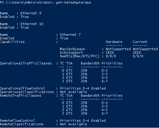
In a scenario where both peers are set to Willing, the adapter with a lower MAC address takes the settings of the peer.
DCBX is disabled in the driver by default and in the some firmware versions as well.
To use DCBX:
Query and enable DCBX in the firmware.
Download the WinMFT package.
Install WinMFT package and go to \Program Files\Mellanox\WinMFT
Get the list of devices, run "mst status".
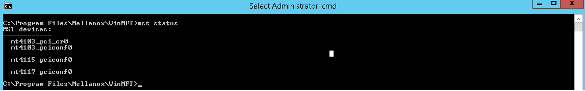
Verify is the DCBX is enabled or disabled, run "mlxconfig.exe -d mt4117_pciconf0 query" .
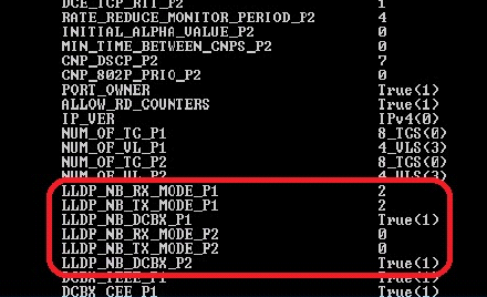
If disabled, run the following commands for a dual-port card.
mlxconfig -d mt4117_pciconf0 set LLDP_NB_RX_MODE_P1=
2mlxconfig -d mt4117_pciconf0 set LLDP_NB_TX_MODE_P1=2mlxconfig -d mt4117_pciconf0 set LLDP_NB_DCBX_P1=1mlxconfig -d mt4117_pciconf0 set LLDP_NB_RX_MODE_P2=2mlxconfig -d mt4117_pciconf0 set LLDP_NB_TX_MODE_P2=2mlxconfig -d mt4117_pciconf0 set LLDP_NB_DCBX_P2=1
Add the "DcbxMode" registry key, set the value to "2" and reload the adapter.
The registry key should be added to HKEY_LOCAL_MACHINE\SYSTEM\CurrentControlSet\Control\Class\{4d36e972-e325-11ce-bfc1-08002be10318}\<IndexValue>
To find the IndexValue, refer to section Finding the Index Value of the Network Interface.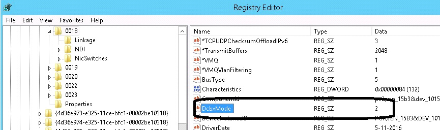
In the event where the device or the Operating System unexpectedly becomes unresponsive for a long period of time, the Flow Control mechanism may send pause frames, which will cause congestion spreading to the entire network.
To prevent this scenario, the device monitors its status continuously, attempting to detect when the receive pipeline is stalled. When the device detects a stall for a period longer than a pre-configured timeout, the Flow Control mechanisms (Global Pause and PFC) are automatically disabled.
If the PFC is in use, and one or more priorities are stalled, the PFC will be disabled on all priorities. When the device detects that the stall has ceased, the flow control mechanism will resume with its previously configured behavior.
This feature enables the system to drop the packets that have been awaiting transmission for a long period of time, preventing the system from hanging. The implementation of the feature complies with the Head of Queue Lifetime Limit (HLL) definition in the InfiniBand™ Architecture Specification.
The HLL has three registry keys for configuration:
TCHeadOfQueueLifeTimeLimit, TCStallCount and TCHeadOfQueueLifeTimeLimitEnable (see section Ethernet Registry Keys).
VXLAN technology provides scalability and security challenges solutions. It requires extension of the traditional stateless offloads to avoid performance drop. ConnectX®-4 and onwards adapter cards offer stateless offloads for a VXLAN packet, similar to the ones offered to non-encapsulated packets. VXLAN protocol encapsulates its packets using outer UDP header.
ConnectX®-4 and onwards support offloading of tasks related to VXLAN packet processing, such as TCP header checksum and VMQ (i.e.: directing incoming VXLAN packets to the appropriate VM queue).
VXLAN Offloading is a global configuration for the adapter. As such, on a dual-port adapter, any modification to one port will apply to the other port as well. Due to a hardware limitation, this will not be shown when querying different ports (e.g. if Port A is modified, this will show up when querying Port A but not Port B.). As such, it is recommended that any modification on one port be applied to the other port using Mlx5Cmd.
VXLAN can be configured using the standardized * VxlanUDPPortNumber and *EncapsulatedPacketTaskOffloadVxlan keys.
A threaded DPC is a DPC that the system executes at IRQL = PASSIVE_LEVEL. An ordinary DPC preempts the execution of all threads, and cannot be preempted by a thread or by another DPC. If the system has a large number of ordinary DPCs queued, or if one of those DPCs runs for a long period time, every thread will remain paused for an arbitrarily long period of time. Thus, each ordinary DPC increases the system latency, which can damage the performance of time-sensitive applications, such as audio or video playback.
Conversely, a threaded DPC can be preempted by an ordinary DPC, but not by other threads. Therefore, the user should use threaded DPCs rather than ordinary DPCs, unless a particular DPC must not be preempted, even by another DPC.
For more information, please refer to Introduction to Threaded DPCs.
[Windows Client 10 18908 (20H1) and later] UDP Segmentation Offload (USO) enables network cards to offload the UDP datagrams' segmentation that are larger than the MTU on the network medium. It is enabled/disabled using standardized registry keys (UsoIPv4 & UsoIPv6) as described in Offload Registry Keys.
UDP Segmentation Offload (USO) is currently supported in ConnectX-4/ConnectX-4 Lx/ConnectX-5 adapter cards only.
Hardware Timestamping is used to implement time-stamping functionality directly into the hardware of the Ethernet physical layer (PHY) using Precision Time Protocol (PTP). Time stamping is performed in the PTP stack when receiving packets from the Ethernet buffer queue.
This feature can be disabled, if desired, through a registry key. Registry key location:
HKLM\SYSTEM\CurrentControlSet\Control\Class\{4d36e972-e325-11ce-bfc1- 08002be10318}\<nn>
For more information on how to find a device index nn, refer to to section Finding the Index Value of the Network Interface..
|
Key Name |
Key Type |
Values |
Description |
|
*PtpHardwareTimestamp |
REG_DWORD |
|
Enables or disables the hardware timestamp feature. |
Hardware Timestamping is supported in Windows Server 2019 and above.
This feature is supported in Ethernet protocol and in ConnectX-5 and above adapter cards.
This feature is supported only when LRO is enabled. LRO minimum value is 16KB and maximum value is 64KB.
Receive buffers size is set to the maximum possible size of incoming messages. Every incoming message that is smaller than the maximum possible size, leaves a unutilized memory in order to increase the memory utilization. Receive buffers are segmented into fixed size strides and each incoming packet (or an LRO aggregate) consumes a buffer of its size (rather than the maximum possible incoming message size.)
This feature allows the user to configure additional MAC addresses for the network adapter without setting the adapter to promiscuous mode. Registering MAC addresses for a network adapter will allow the adapter to accept packets with the registered MAC address.
This feature is supported in Ethernet protocol and native mode only.
Configuring Additional MAC Addresses:
The additional MAC addresses are configured using the mlx5cmd tool.
To view the adapter's current configuration:
mlx5cmd -MacAddressList -Name <Adapter name> -Query
To add additional MAC addresses (three in the example below): mlx5cmd -MacAddressList -Name <Adapter name> -Add -Entries 3 AB-CD-EF-AB-CD-E0 AB-CD-EF-AB-CD-E1 AB-CD-EF-AB-CD-E2
To delete more than 1 MAC addresses (two in the example below):mlx5cmd -MacAddressList -Name "Ethernet" -Delete -Entries 2 AB-CD-EF-AC-CD-E1 AB-CD-EF-AC-CD-E2
In a multi-host system, a single receive buffer is used for all hosts. If one or more host(s) are being congested, the congested host(s) can exhaust the device’s receive buffer and cause service degradation for the other host(s). In order to manage this situation, the device can mark the ECN (Explicit Congestion Notification) bits in the IP header for the congested hosts. When ECN is enabled on the host, the host will sense the ECN marking and will reduce the TCP traffic and by that will throttle the traffic.
For the ECN related software counters refer to WinOF-2 Receive Datapath and WinOF-2 PCI Device Diagnostic.
The feature is supported only for lossy traffic, single port adapter cards, and TCP traffic.
Registry keys:
|
Name |
Description |
|
|
CongestionMonitoringEnable |
Driver will read CQE hint to mark ECN in the packet. Registry key is dynamic. |
|
|
CongestionAction |
When overflow encountered by hardware for lossy traffic, packets will either be dropped or marked for driver to get hint in CQE. Values can be changed only when CongestionMonitoringEnable is set to 1. Registry key is dynamic. |
|
|
CongestionMode |
Programs hardware to be in aggressive mode where traffic is dropped/marked in an aggressive way, or in dynamic mode where the drop/mark in more relaxed. Values can be changed only when CongestionMonitoringEnable is set to 1. Registry key is dynamic. |
|
Windows introduced a new poll mode feature starting NDIS 6.85 onwards. The poll API handles Datapath processing for both TX and/or RX side. When the feature is enabled, the driver registers with NDIS for call backs to poll RX and/or TX data.
Enabling/Disabling NDIS Poll Mode
The registry keys used to enable/disable this capability are not dynamic. At this time, the registry keys are not exposed in the INF as the operating system is not GA as yet.
|
Registry Name |
Value |
Comments |
|
RecvCompletionMethod |
Set to 4 to register and use Ndis Poll Mode |
Default is 1 (Adaptive) |
|
SendCompletionMethod |
Set to 2 to register and use Ndis Poll Mode |
Default is 1 (Interrupt) |
Limitations
When enabled on RX side, the following capabilities are not be supported:
AsyncReceiveIndicate
Receive side Threaded DPC
Force low resource indication
When enabled on TX side, the following capabilities are not be supported:
Transmit side Threaded DPC
TxMaxPostSendsCoalescing is limited to 32
Peer-to-Peer data transfers allows direct data transfer between PCIe devices without the need to use system main memory as a temporary storage or use of the CPU for moving data. When one peer is a NIC while the other peer is a GPU, it allows the NIC to have direct access to the GPU memory and transfer data through the network, bypassing the CPU and reducing memory copy operations.
This feature can be enabled or disabled by setting registry key below:
|
Key Name |
Key Type |
Values |
Descriptions |
|
EnableGpuDirect |
REG_DWORD |
[0, 1] |
This registry key enables or disables this feature. Note: Restart the network adapter after you change this registry key. |
The registry key should be added to:
HKEY_LOCAL_MACHINE\SYSTEM\CurrentControlSet\Control\Class\{4d36e972-e325-11ce-bfc1-08002be10318}\<IndexValue>
To find the IndexValue, refer to section Finding the Index Value of the Network Interface.
Feature Requirements
RDMA support: To enable RDMA, please see section RDMA over Converged Ethernet (RoCE).
DevX Interface support: To enable DevX Interface, please see section DevX Interface.
NVIDIA Turing Architecture Quadro GPUs and later, e.g. Quadro RTX 4000.
NVIDIA GPU driver support: R470 and later.
Feature Limitations
The current NIC and GPU kernel driver implementations do not support memory region registration on GPU memory buffer larger than 4 GB.
From NDIS 6.84+, Windows supports Hardware QoS Offload for the VMQoS capability. This feature allows moving egress bandwidth management entirely into the hardware. It allocates explicit Schedule Queues (SQs) on the physical NIC with bandwidth limits and guarantees reservations on a per-Traffic class basis.
To get full functionally of the feature, the users must set the "SendQueuePerPrio" key to 1 on the hypervisor and on the Virtual Machines.
Currently, the driver only supports enabling all TCs or none for an SQ.
For ConnectX-5 and above adapter cards, only TC0 traffic will be limited over the synthetic path.
This feature can be enabled or disabled by setting the registry key below:
|
Key Name |
Key Type |
Values |
Descriptions |
|
*QoSOffload |
REG_SZ |
[0, 1] |
This registry key enables or disables HwQoS. Note: Restart the network adapter after updating the registry key. |
|
*QosOffloadSupportedTCs |
REG_SZ |
[0, 0xFF] Default 0xFF |
This registry key indicates which traffic classes HwQoS should be applied to. Each set bit indicates that traffic class should be supported. Note: Restart the network adapter after updating the registry key. |
|
SendQueuePerPrio |
REG_SZ |
[0, 1] |
This key controls how the driver will open a single queue for each priority when the key is disbaled. 1 queue will be used for all prioritties. Note: Enabling this feature increases the alocated resources darmatically and therefore should be enbaled only when using Hardware QoS. |
To check the status of this feature, run the following command:
mlx5cmd -features -name <adapter name>