Overview
VPI is a library that provides a collection of computer vision and image processing algorithms that can be seamlessly executed in a variety of hardware accelerators, called backends.
The goal is to provide a uniform interface to these backends, while maintaining high performance. To achieve that, several shared memory mapping mechanisms between backends are used, depending on memory characteristics, coupled with high performance implementations of algorithms and availability of backend-agnostic event synchronization mechanisms.
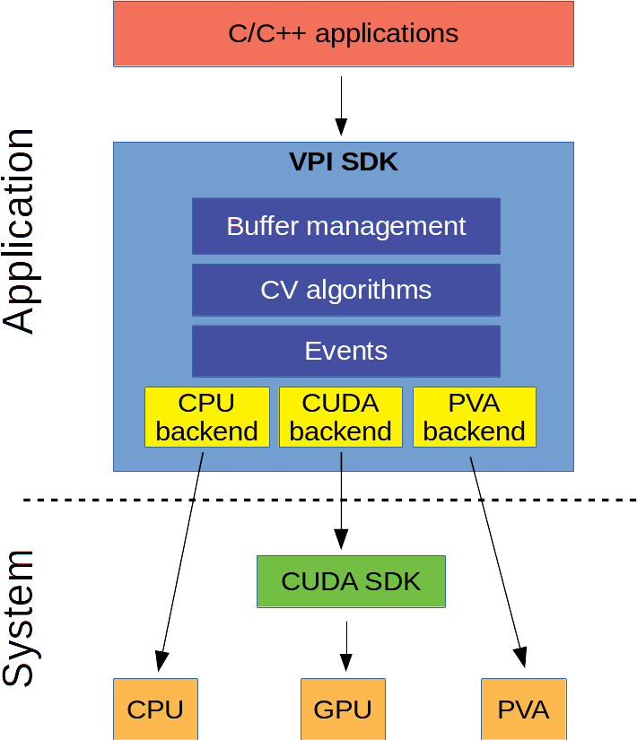
The VPI architectural overview is as follows:
The API follows the paradigm where object allocation and setup take place in an initialization phase. The application loop follows, where the main processing occurs, using the objects created during initialization. Once completed, the created objects are destroyed and the environment is cleaned up. For robotics software applications where memory allocations are limited in both time and space, this environment cleanup is beneficial.
The core components of VPI include:
- Context: holds the state of VPI and created objects.
- Streams: acts as an asynchronous queue to where algorithms are submitted and ultimately executed sequentially on a given backend.
- Buffers: stores input and output data.
- Algorithms: performs operations on buffers.
- Events: provides synchronization primitives.
Pipeline examples, and how to implement them using VPI, are explained in the following sections.
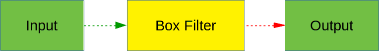
Simple Pipeline
In this example, a simple pipeline is implemented with a given input image. A box filter is applied and produces a blurred version.
The code for implementing the pipeline is as follows.
- Note
- For simplicity, function return values for errors are not checked. Consult the bundled samples for examples of complete, yet simple applications.
Include necessary headers. In this example, image buffers are used, a stream, and the
BoxImageFilteralgorithm.Create the image buffers to be used.
int main(){VPIImage input, output;vpiImageCreate(640, 480, VPI_IMAGE_TYPE_Y8, 0, &input);vpiImageCreate(640, 480, VPI_IMAGE_TYPE_Y8, 0, &output);A 640x480 1-channel (grayscale) input image is created with unsigned 8-bit pixel elements, represented by
VPI_IMAGE_TYPE_Y8enum (Y stands for luma). Images are initialized with zeros upon creation. The intent is to work with all backends supported, pass 0 as flags, and pass the pointer to where the image handle will be written. The output image is created the same way.- Note
- In this example, an empty input image buffer is created. However, in a real scenario an existing memory can be wrapped into a VPI image buffer, or an image from an earlier pipeline stage can be used.
Create a CUDA stream to execute the algorithm on the first CUDA device detected on the system. The function returns an error if no such devices exist or can be used.
VPIStream stream;vpiStreamCreate(VPI_DEVICE_TYPE_CUDA, &stream);Submit the box filter algorithm to the stream, passing along the input and output images, and other parameters; such as 3x3 kernel, and clamp boundary condition.
vpiSubmitBoxImageFilter(stream, input, output, 3, 3, VPI_BOUNDARY_COND_CLAMP);Because of the asynchronous nature of streams, the algorithm is pushed to the CUDA execution queue of the stream, and the function returns immediately. This allows the program to continue assembling the processing pipeline, or do something else, while the algorithm executes.
Wait until the stream finishes processing.
vpiStreamSync(stream);This function blocks until all algorithms submitted to the stream finish executing. This function must be called to show the output to the user, to save it to disk, etc.
Destroy created objects.
Upon completion, destroy the created objects to avoid memory leaks. Destroying a stream forces it to synchronize, but destroying images that are still being used by an algorithm leads to undefined behavior, likely resulting in a program crash.
Examining how several VPI objects work together, and inspecting the ownership relationship between objects is a beneficial learning exercise. The structure of the provided example is as follows.
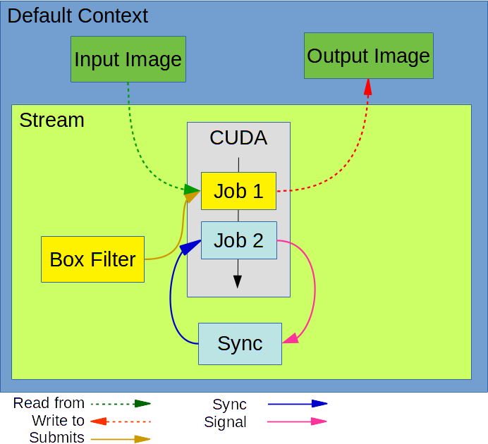
Where:
- Default Context is the context that is automatically created and made active in all existing or future host threads. It owns all objects created while it is active. In this example, this is the stream and the image buffers.
- Stream contains an asynchronous CUDA queue and owns an instance of the algorithm, along with an event used for synchronization.
- Box Filter algorithm gets submitted to the stream, the job Job1 gets created with a reference of the algorithm instance and all its parameters. This job gets pushed to the asynchronous queue, and if the queue is empty, the algorithm begins executing immediately.
Finally, the call to vpiStreamSync adds a Sync event job Job2 to the queue and blocks processing on the calling thread. This event gets signaled once Job1 finishes, unblocking the call and allowing the calling thread to continue.
Complex Pipeline
More complex scenarios can be envisioned that take advantage of different acceleration processors on the device and create a pipeline that strives to fully utilize the computational power.
To do that, the pipeline must have parallelizable stages. For example, the pipeline, given a stereo pair, calculates the stereo disparity and extracts Harris keypoints from the right image.
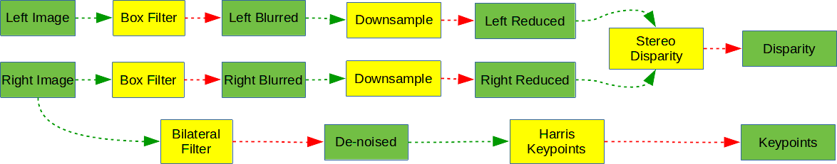
Three stage parallelization opportunities are identified: the independent left and right image pre-processing, and Harris keypoint extraction. A different backend can be designated for each one of these parallel streams, depending on the processing speed of each backend, power requirements, input and output restrictions, and availability. In this example, the whole processing among CUDA, PVA and CPU backends is split:
- PVA: handles stereo pair pre-processing
- CUDA: handles stereo disparity calculation
- CPU: handles extraction of Harris keypoints
The rationale for this choice is that since PVA can handle up to four streams completely in parallel, two of them can be used to process the stereo pair. The CPU, which is usually slower, is kept busy performing Harris keypoints undisturbed. Finally, CUDA handles the PVA output and calculates the stereo disparity at the end.
In the sequence diagram that follows:
- The Host column represents the main thread that sets up the processing pipeline.
- The other columns are for the streams to be used.
- The arrows depict which stream each call acts on.
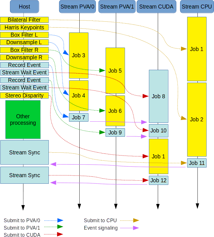
As shown in the diagram, the fact that CUDA is idle during PVA processing leaves it free to do some other tasks outside VPI, such as Deep Learning inference stages.
Notice how a barrier is implemented using the event primitives. Stereo disparity must start after the PVA streams complete processing their data. One event is set up for each PVA stream to be signaled when it is done. The CUDA stream waits until this happens. Only then it is allowed to proceed and work on the PVA output.
The code that implements this pipeline is explained as follows.
- Start with the initialization phase, where all the required objects are created.
- Include headers for all the objects used, as well as all the required algorithms. #include <vpi/Context.h>#include <vpi/Image.h>#include <vpi/Array.h>#include <vpi/Event.h>#include <vpi/Stream.h>#include <vpi/algo/BoxImageFilter.h>#include <vpi/algo/BilateralImageFilter.h>#include <vpi/algo/HarrisKeypointDetector.h>#include <vpi/algo/StereoDisparityEstimator.h>#include <vpi/algo/ImageResampler.h>
Create a context and make it active.
Although the default context that is automatically created to manage the VPI state can be used, it is easier to create a context and use it to handle the lifetime of all objects created under it. In the end, the context and all objects are automatically destroyed, reducing the chances of leaking memory. This approach makes sense because many objects are being created.
Create the streams.
During stream creation, specify the backend, also called device type, that will ultimately execute the submitted algorithms.
Two PVA streams are instantiated. In Jetson AGX Xavier there are two PVA processors, each one capable of processing two streams in parallel. VPI implements a simplistic form of load balancing between them, where PVA stream creation picks one of the available PVA processors in a round-robin fashion. The PVA processor, in turn, picks an available stream also using round-robin fashion.
VPIStream stream_cuda, stream_cpu, stream_pva0, stream_pva1;vpiStreamCreate(VPI_DEVICE_TYPE_CUDA, &stream_cuda);vpiStreamCreate(VPI_DEVICE_TYPE_CPU, &stream_cpu);vpiStreamCreate(VPI_DEVICE_TYPE_PVA, &stream_pva0);vpiStreamCreate(VPI_DEVICE_TYPE_PVA, &stream_pva1);Create stereo pipeline images.
Again, similar to the simple pipeline, create empty input images. In reality these input images must be populated by either wrapping existing memory, or by being the result of an earlier VPI pipeline.
The input is a 640x480 stereo pair, 16-bit unsigned pixels (HDR). The temporary images for the blurred and reduced copies and the image with the disparity map to be estimated are created. The result is a down-sampling of the input to make stereo disparity processing faster, since high resolution disparity map is not required.
VPIImage left, right;vpiImageCreate(640, 480, VPI_IMAGE_TYPE_Y16, 0, &left);vpiImageCreate(640, 480, VPI_IMAGE_TYPE_Y16, 0, &right);VPIImage left_blurred, right_blurred;vpiImageCreate(640, 480, VPI_IMAGE_TYPE_Y16, 0, &left_blurred);vpiImageCreate(640, 480, VPI_IMAGE_TYPE_Y16, 0, &right_blurred);VPIImage left_reduced, right_reduced;vpiImageCreate(480, 270, VPI_IMAGE_TYPE_Y16, 0, &left_reduced);vpiImageCreate(480, 270, VPI_IMAGE_TYPE_Y16, 0, &right_reduced);VPIImage disparity;vpiImageCreate(480, 270, VPI_IMAGE_TYPE_Y16, 0, &disparity);Define stereo disparity algorithm parameters.
The VPI stereo disparity estimator is implemented by a semi-global stereo matching algorithm. The estimator requires the census transform window size, specified as 5, and the maximum disparity levels, specified as 64.
VPIStereoDisparityEstimatorParams stereo_params;stereo_params.windowSize = 5;stereo_params.maxDisparity = 64;Create the stereo disparity payload.
Stereo disparity processing requires some temporary data. VPI calls it payload. In this example, vpiCreateStereoDisparityEstimator is called and passed all the required parameters by the internal allocator to decide the size of the temporary data.
Because the temporary data is allocated on a backend device, the payload is tightly coupled to the backend. If the same algorithm is needed in different streams, one payload for each must be created. In this example, it is created for the CUDA stream.
VPIPayload stereo_cuda;vpiCreateStereoDisparityEstimator(stream_cuda, 480, 270, VPI_IMAGE_TYPE_Y16,stereo_params.maxDisparity, &stereo_cuda);Create image and array buffers for Harris keypoint detector.
This algorithm receives an image and outputs two arrays, one with the keypoints themselves and another with the score of each keypoint. At most, 8192 keypoints are allowed to be found. Keypoints are represented by the VPIKeypoint structure and scores are 32-bit unsigned values.
VPIImage denoised;vpiImageCreate(640, 480, VPI_IMAGE_TYPE_Y16, 0, &denoised);VPIArray keypoints, scores;vpiArrayCreate(8192, VPI_ARRAY_TYPE_KEYPOINT, 0, &keypoints);vpiArrayCreate(8192, VPI_ARRAY_TYPE_U32, 0, &scores);Define Harris detector parameters.
Fill the VPIHarrisKeypointDetectorParams structure with the required parameters. Refer to the structure documentation for more information about each parameter.
VPIHarrisKeypointDetectorParams harris_params;harris_params.gradientSize = 5;harris_params.blockSize = 5;harris_params.strengthThresh = 10;harris_params.sensitivity = 0.4f;harris_params.minNMSDistance = 8;Create the Harris detector payload.
Like stereo disparity, Harris detector requires a payload. This time only the input size, 640x480 is needed. When using this payload, only inputs of this size are accepted.
VPIPayload harris_cpu;vpiCreateHarrisKeypointDetector(stream_cpu, 640, 480, &harris_cpu);Create the events to implement a barrier synchronization.
CUDA stream must wait for two PVA streams to finish their job, consequently two events are required, one for each stream.
VPIEvent barrier_pva0, barrier_pva1;vpiEventCreate(0, &barrier_pva0);vpiEventCreate(0, &barrier_pva1);
- Include headers for all the objects used, as well as all the required algorithms.
- The initialization is complete. Now comes the main processing phase where the pipeline is implemented by submitting algorithms and events in the correct order. This processing can occur many times in a loop using the same events, payloads, temporary, and output buffers. Naturally, the input is usually different in each iteration. If the input images are wrapping external memory, such as current frame from a stereo camera, nothing else must be done other than fetching a new camera frame.
Implement the keypoint detector pipeline. Perform a simplistic de-noise pass with the bilateral filter, then use Harris detector to get the keypoints.
vpiSubmitBilateralImageFilter(stream_cpu, right, denoised, 5, 5, 1.2, VPI_BOUNDARY_COND_CLAMP);vpiSubmitHarrisKeypointDetector(harris_cpu, denoised, keypoints, scores, &harris_params);- Implement the pre-processing stages for the stereo disparity on the two PVA streams.
Start with the pre-processing of the left image: a low-pass filter followed by image down-sampling using bilinear interpolation.
vpiSubmitBoxImageFilter(stream_pva0, left, left_blurred, 3, 3, VPI_BOUNDARY_COND_ZERO);vpiSubmitImageResampler(stream_pva0, left_blurred, left_reduced, VPI_INTERP_LINEAR, VPI_BOUNDARY_COND_ZERO);The right image processing is exactly the same.
vpiSubmitBoxImageFilter(stream_pva0, right, right_blurred, 3, 3, VPI_BOUNDARY_COND_ZERO);vpiSubmitImageResampler(stream_pva0, right_blurred, right_reduced, VPI_INTERP_LINEAR, VPI_BOUNDARY_COND_ZERO);
Implement the barrier synchronization.
Use the vpiEventRecord function to record, in each event, the corresponding PVA stream state at this point. Since all jobs are already submitted, these events are signaled once all the jobs submitted at this point get processed.
Then the vpiStreamWaitFor call submits jobs to the CUDA stream, making it wait until both events get signaled. At the point the stream execution is released from this wait, the data for stereo disparity will be ready to be processed.
vpiEventRecord(barrier_pva0, stream_pva0);vpiStreamWaitFor(stream_cuda, barrier_pva0);vpiEventRecord(barrier_pva1, stream_pva1);vpiStreamWaitFor(stream_cuda, barrier_pva1);Submit the stereo disparity algorithm.
At this point the input images are ready. Call vpiSubmitStereoDisparityEstimator to the CUDA stream for processing.
vpiSubmitStereoDisparityEstimator(stereo_cuda, left_reduced, right_reduced, disparity, &stereo_params);Synchronize the streams to use the disparity map and keypoints detected.
Remember that the functions called so far in processing phase are all asynchronous; they return immediately once the job is queued on the stream for later execution.
Now, more processing can be performed on the main thread, such as update some GUI status or showing the previous frame. This occurs while VPI is executing the pipeline. Once this additional processing is performed, synchronize the streams that are processing the final result using vpiStreamSync. Once completed, the resulting buffers can be accessed. Once this is done, loop back to the beginning of the processing phase or go to the deinitialization phase.
vpiStreamSync(stream_cuda);vpiStreamSync(stream_cpu);
Context destruction.
In this example, many objects were created under the current context. Once all processing is completed and the pipeline is no longer required, destroy the context. All streams will be synchronized and destroyed, along with all other objects used. No memory leaks are possible.
Destroying the current context activates the previous context that was active before the former was set to active.
vpiContextDestroy(ctx);}
Important takeaways from these examples:
- Algorithm submission returns immediately.
- Algorithm execution occurs asynchronously with respect to the host thread.
- The same algorithm can be submitted multiple times with different parameters.
- The streams own the algorithm payload; the same algorithm payload cannot be submitted to different streams.
- Buffers can be used by different streams, although race conditions must be avoided through the use of events.
- Context owns all objects created by one user thread while it is in an active state. This allows some interesting scenarios where one thread sets up the context and triggers all the processing pipeline, then moves the whole context to another thread that waits for the pipeline to end, then triggers further data processing.
Contexts
VPI contexts serve as a container of other VPI objects along with some configurations that apply to them.
Every host thread has an active context. VPI objects created while a context is active are owned by it.
For user-created contexts, the user can specify during creation what backends this context supports at most. This effectively allows the user to mask support for a particular hardware. For example, creating a stream for CUDA backend fails if the current context has the VPI_CONTEXT_NO_CUDA flag set. These flags are automatically updated to reflect the actual platform support for a particular backend. For example, if PVA backend is not available, contexts will have the flag VPI_CONTEXT_NO_PVA set by default. However, note that the CPU backend cannot be masked out and must always be supported as a fallback implementation.
Sharing objects (buffers, payloads, events, ...) among different contexts is not permitted.
There can be a maximum of 8 user contexts created at any given time.
The current context can be manipulated by the user if needed.
Global Context
By default, there is a single global context created before the first VPI object is created.
This global context is initially shared among all user threads and cannot be destroyed by the user.
For most applications, the user can use the global context. When some finer control is required, for how objects are grouped together, or some level of independence is needed, the user may wish to explicitly create and manipulate contexts.
Context Stack
Each user thread has a context stack not shared with other threads.
The top context in the stack is the current context for that thread.
By default, the context stack has one context in it, the global context. Consequently, all new threads have the same global context set as current thread.
Making a context current in a given stack amounts to replacing the top context, either the global context or the most recently pushed context, with the given context. The replaced context does not belong to the stack anymore.
However, pushing a context into a stack does not replace anything. The top context is kept in the stack and the new pushed context is put at the top, thereby becoming the new current context.
The user can push and pop contexts from the stack at will. This allows for temporarily creating pipelines in a new context without disturbing the existing context.
To avoid leakage, it is important to match the number of pushes and pops on a given context stack. Be aware that the context stack can have at most 8 contexts in it.
Streams
The main entry-point to the API is the VPIStream object. This object represents:
- A backend-specific resource handle – creating
VPIStreaminstance for a specific backend allocates system resources and sets up the hardware to run API functionality. - A command queue – FIFO queue storing a list of commands to execute. Command may comprise of running a particular CV function or signaling an event. This allows the API functions to be executed asynchronously with respect to the calling thread. Invoking any CV function pushes a corresponding command to the
VPIStreaminstance command queue and immediately returns. The queued commands gets consumed by the underlying backend implementation. - An owner of device-specific algorithm instance or, so called, function payloads –
VPIPayload.
There can be at most 8 streams allocated in a given context.
Backend Types
The API supports creating stream instances for 3 backends: CUDA, CPU, and PVA. The total number of stream instances for each backend is currently limited to 8. Also, at most 8 streams of any type can be created under the same VPI context. VPI permits simultaneous creation and use of multiple instances of the same type. For many CV algorithms, this is the only way to saturate the underlying backend (CUDA/PVA).
Each stream may launch a task queue thread to handle asynchronous task execution. It is not specified when the thread is created. However, this is usually upon stream creation, lasting until it is destroyed.
- CPU
- Along with the task queue thread, it may create a set of background worker threads and data structures supporting efficient parallel execution.
- The implementation may choose to share the worker thread pool between different streams and/or context instances.
- CUDA
- Has an explicit affinity, defined during construction, with a particular CUDA device.
- Lightweight, stores CUDA pointer stream and other CUDA device information that allows launching of the underlying kernels on a specific device/stream.
- In some situations, specially in presence of user-defined functions submitted to the stream, it uses a task queue thread to execute it. While there are many user-defined functions to be executed, VPI algorithms are launched from this worker thread instead the caller thread.
- Prior the API context construction, it is up to the user to properly setup the CUDA context for the calling thread. The resulting context object uses the corresponding CUDA context for internal kernel calls.
- PVA
- Every instance of a PVA stream chooses one available PVA processor in a round-robin fashion.
- Works similarly to CUDA device regarding submission of user-defined functions, especially regarding the use of a worker thread.
Buffers
Buffers represent the data VPI algorithms work with. Abstractions for three kinds of data are provided:
- Images: stores 2-dimensional data
- Arrays: for 1-dimensional data
- Pyramids: an array of images with varying detail, from finer to coarse.
Users can have VPI manage allocation of all three types of buffers. Or, for images and arrays, existing memory can be wrapped into a VPI buffer. The This is useful when interoperability with other libraries is required, such as using a OpenCV cv::Mat buffer as input to a VPI algorithm.
Common attributes for all buffer types are their size and the element type.
Images
VPI images represent any kind of 2D data, such as images themselves, vector fields embedded in a 2D space, 2D heat maps, etc.
The images are characterized by their width, height, element type and flags.
The flags are used to specify which backend can work with them. Passing 0 means to make the image work with all available backends. If some backends won't be used, pass any of the following flags, or'ed together if needed:
VPI also provides the following helper flags when only one backend is needed:
Locking
Image data can be accessed from host using the vpiImageLock function. The function requires that the image have the CPU backend enabled. It will fill the VPIImageData with image information that allows the user to properly address and interpret all image pixels. Once the user is done working on the image data from host, vpiImageUnlock must be called. Once the image is locked, it can't be locked again, nor accessed from an algorithm running asynchronously in a VPI stream.
Image Types
VPI supports a variety of image types representing different element types, such as single-channel 8-, 16- or 32-bit, unsigned and signed, multi-channel RGB and RGBA, multi-planar NV12. Not all algorithms support images with all types. The image type documentation defines the proper constraints on images.
Wrapping External Memory
Users can create images that wrap externally allocated CUDA and host memory using the functions vpiImageWrapCudaDeviceMem and vpiImageWrapHostMem respectively. In both cases, the user must fill a VPIImageData structure with the required information and pass it to the function.
It's also possible to wrap an EGLImage handle using vpiImageWrapEglImage. In all these cases, the VPIImage object doesn't own the memory buffer. When the VPIImage is destroyed, the buffer isn't deallocated.
Arrays
VPI arrays represent 1D data, such as keypoint lists, bounding boxes, transforms, etc.
Arrays are characterized by their capacity, size, element type and flags. As with images, the flags are used to specify which backend can work with them.
The following flags are available for arrays:
Similarly, when only one backend is needed, pass one of the following flags:
Locking
Array data can be accessed from host using the vpiArrayLock function. It works like its image counterpart.
VPIArray has a unique feature that while the capacity of the array is fixed for the lifetime of the object, the size can change. Any API that outputs to an array will set the size parameter to the number of valid elements contained in the array. The user also has the ability to use vpiArrayGetSize and vpiArraySetSize to query and modify the size of an array, but these APIs can only be used while an array is locked and accessible from host. Another constraint is that in order to update the array's size, it must be locked for writing, done by passing VPI_LOCK_READ_WRITE to vpiArrayLock.
Wrapping External Memory
Users can also create arrays that wrap externally allocated CUDA and host memory using the functions vpiArrayWrapCudaDeviceMem and vpiArrayWrapHostMem respectively. In both cases, the user must fill a VPIArrayData structure with the required information and pass it to the function.
Pyramids
VPI pyramids represent a collection of VPI images stacked together, all having the same type, but possibly different dimensions.
Pyramids are characterized by their number of levels, base level dimensions, scale factor and image type. The scale factor represents the ratio of one level dimension over the prior level dimension. For instance, when scale=0.5, the pyramid is dyadic.
Often it's required to process one pyramid level as input or output to a VPI algorithm. The user must then use vpiImageWrapPyramidLevel specifying the pyramid and which level is to be wrapped. The returned VPIImage handle can be used as any other image. Once work on this image is done, it must be destroyed with vpiImageDestroy.
Locking
As with images and arrays, the user can access the whole pyramid data from host using the function vpiPyramidLock, provided that the pyramid is enabled for CPU backend. This function fills a VPIPyramidData structure that is basically a vector of VPIImageData. Once work with VPIPyramidData is done, call vpiPyramidUnlock to unmap the pyramid from host and free resources. Once a pyramid is locked, it can't be locked again, nor be used by a VPI algorithm.
Events
Each compute function in the API is executed asynchronously with respect to the calling thread, i.e., returns immediately without waiting for the completion. There are two ways of synchronizing with the backend. One is to wait until all the commands in the VPIStream queue are finished, with vpiStreamSync call. This approach, while simple, doesn't allow for fine-grained ("wait until function X is completed") or inter-stream ("before running function A in stream B, wait until function C in stream D finishes") synchronization. That's where VPIEvent objects come in. Conceptually they correspond to binary semaphores and are designed to closely mimic events in CUDA API:
- Users can capture all commands submitted to a VPIStream instance in an event instance (see vpiEventRecord). The event is considered completed when all captured commands have been processed and removed from VPIStream command queue.
- Inter-stream synchronization is possible with the vpiStreamWaitFor call that pushes a command to VPIStream queue that blocks processing of future queued commands until the given event is completed.
- Host threads can query the event's state with vpiEventQuery
- Host threads can block until the event is completed with vpiEventSync.
- Events can be time-stamped when completed.
- The user can compute time-stamp difference between completed events in the same stream as well as between different streams.
Thread-Safety
All API functions are thread-safe. Concurrent host access to API objects is serialized and executed in an unspecified order. All API calls use a VPIContext instance that is thread-specific and stored in TLS. If the context pointer for the current thread is NULL (no context is set), all API calls will use a default "global" context created during library initialization. API objects have no concept of thread affinity; in other words, if both threads use the same context instance, the object created in one thread can be safely destroyed by another thread.
Most of the API functions are non-blocking. Specifically, the set of functions that can block when called is limited to: vpiStreamSync, vpiStreamDestroy, vpiContextDestroy, vpiEventSync and the several vpiSubmit* functions when the stream job queue is full. Since implicit synchronization in the API implementation is minimal, it's up to the user to make sure the resulting order of dependent function calls is legal. Invalid calls, however, should be always handled gracefully (via an appropriate error code) and should not lead to application crashes or corruption of objects' internal state.
The device command queue model is loosely based on CUDA Stream API, and can be summarized with the following:
- A VPIStream instance holds a queue of a jobs to be executed in a given backend.
- Calling an API function is equivalent to the host pushing a command to the queue and continuing immediately
- Backend schedules work from the stream queue when hardware resources are free
- Computer vision functions or event signaling commands are placed within the queue
- Commands in a stream instance are ordered (FIFO) and cannot overlap in time
- Commands between stream instances are unordered and can overlap in time (and backend)
- Inter-stream synchronization and order of execution can be controlled with
VPIEventobjects - The API does not support sharing objects across different processes. All contexts are implicitly bound to the process they were created in.