Overview
Remap applies a generic geometrical transformation to an image. Typical uses include:
- Lens distortion correction.
- User-defined border extension.
- Conversion between different projections.
The algorithm can work on dense or sparse warp maps. A dense warp map stores the remapped position of all pixels in the output image, whereas a sparse map stores a subset of that. It's more efficient to process the latter than the former, but quality might decrease depending on how much distortion is applied by the mapping.
The example below shows the famous "Little Planet" (stereographic) projection applied to a equirectangular panorama image, where \(R\) is the planet radius.
| Input | Mapping | Result |
|---|---|---|
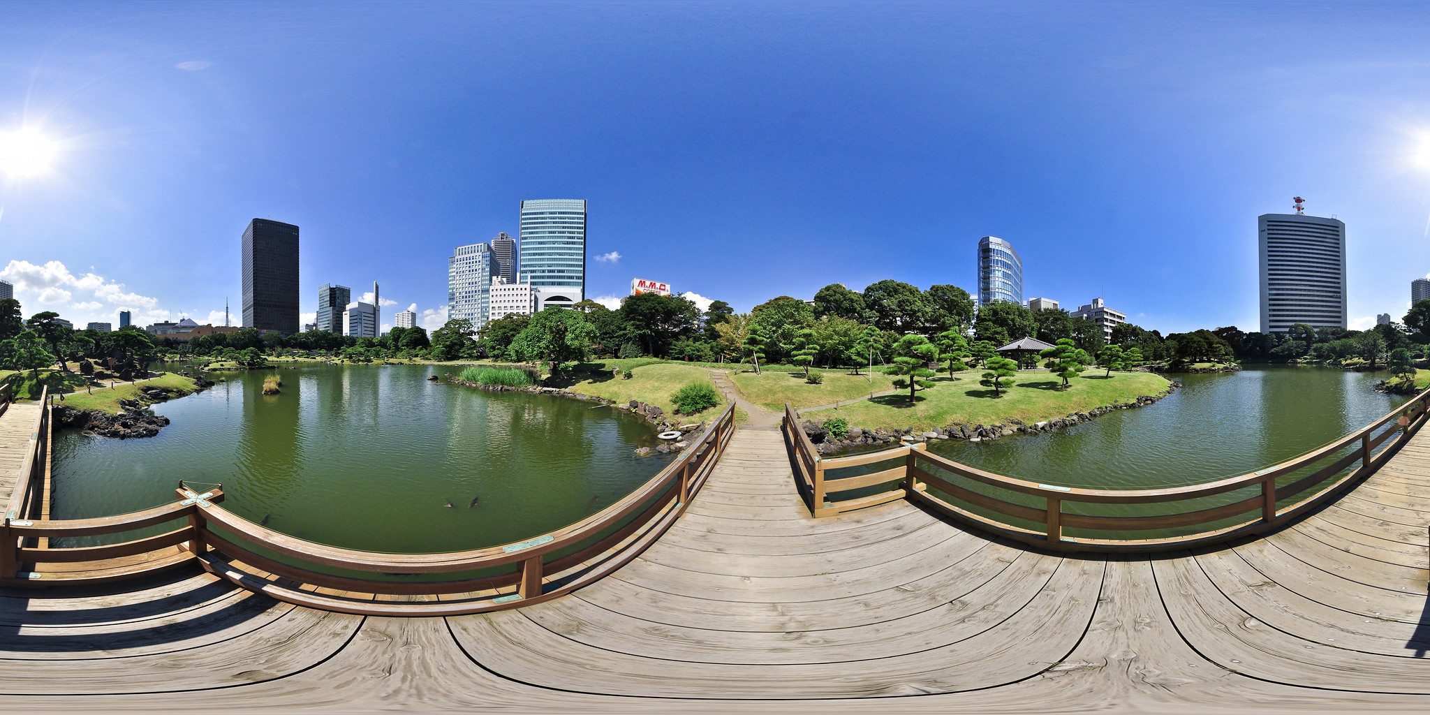 Kyu Shiba Rikyu Garden: on the bridge by heiwa4126 is licensed under CC BY 2.0 | \begin{align*} \theta(x,y) &= \pi + \arctan\left(\frac{y}{x}\right) \\ \phi(x,y) &= \frac{\pi}{2} - 2\arctan\left(\frac{r}{2R}\right) \\ r &= \sqrt{x^2+y^2} \\ \end{align*} |  This image is a derivative of Kyu Shiba Rikyu Garden: on the bridge by heiwa4126, used under CC BY 2.0 |
Implementation
The algorithm uses a user-provided VPIWarpMap that maps every pixel in the output image to the corresponding pixel in the input image. It supports dense and sparse mappings.
The mapping operation is composed of two steps:
- A dense map is generated by up-sampling the input sparse map using bi-quadratic interpolation.
- The pixel in the input image corresponding to the control point in the output image is sampled using the user-provided interpolator.
When the corresponding source pixel falls outside image border, Remap will use the border extension to decide what pixel value to pick.
Warp grid definition
Warp grids can be of 3 types:
- dense: provides maximum quality in exchange for some performance hit.
- uniformly sparse: provides a balance between quality and speed. Useful when the distribution of details in the resulting image isn't known a priori.
- non-uniformly sparse: Useful when distribution of details in the resulting image is known. This allows increased quality and performance by sampling less in areas with low detail, and sampling more densely in areas with more detail.
When defining a sparse map, the output image can be split into at most 16 regions (4 horizontally and 4 vertically), with different control point interval (density) in each row or column of regions. The interval spacing must be expressed in power-of-two number of pixels in between control points. There are some other restrictions in the grid layout. Please consult VPIWarpGrid for more information.
To define a dense map, simply set up the warp grid to have just one region, and both horizontal and vertical spacing to 1.
C API functions
For list of limitations, constraints and backends that implements the algorithm, consult reference documentation of the following functions:
| Function | Description |
|---|---|
| vpiCreateRemap | Create a payload for Remap algorithm. |
| vpiSubmitRemap | Submits a Remap operation to the stream. |
Usage
Language:- Import VPI module import vpi
- Create a identity warp map, i.e., all control points' position will match their position in the output image. Here the warp map is dense with same dimensions as input image. warp = vpi.WarpMap(vpi.WarpGrid(input.size))
- Interpret warp map coordinates as a numpy array. No copies are made. The numpy array has shape (H,W,2) and is a view of the warp map. The shape transposition to (2,W,H) is just to have the
xandycoordinates in the arrayswxandwyrespectively. This makes coordinates' manipulation easier and more efficient.wx,wy = np.asarray(warp).transpose(2,1,0) - Generate a custom mapping suitable to render an equirectangular panorama with the "Little Planet" effect. A similar approach is also taken when performing lens distortion correction for a lens whose distortion model doesn't match the ones provided by VPI. See Lens Distortion Correction for more details. x = wx-input.width/2y = wy-input.height/2R = input.height/8 # planet radiusr = np.sqrt(x*x + y*y)theta = np.pi + np.arctan2(y,x)phi = np.pi/2 - 2*np.arctan2(r, 2*R)wx[:] = np.fmod((theta + np.pi)/(2*np.pi)*(input.width-1), input.width-1)wy[:] = (phi + np.pi/2) / np.pi*(input.height-1)
- Executes the algorithm, it'll transform the VPI image input using the warp map created, writing the result into the output VPI image. with vpi.Backend.CUDA:output = input.remap(warp)
- Initialization phase
- Include the header that defines the Remap functions and VPIWarpMap definition. #include <vpi/WarpMap.h>#include <vpi/algo/Remap.h>Declares functions that implement the Remap algorithm.Declares functions that implement the WarpMap structure and related functions.
- Define the input image object. VPIImage input = /*...*/;
- Create the output image. In this particular case both input and output have same dimensions, but this is not required. The formats must match, though. int32_t w, h;vpiImageGetSize(input, &w, &h);VPIImageFormat type;vpiImageGetFormat(input, &type);VPIImage output;vpiImageCreate(w, h, type, 0, &output);VPIStatus vpiImageGetFormat(VPIImage img, VPIImageFormat *format)Get the image format.VPIStatus vpiImageCreate(int32_t width, int32_t height, VPIImageFormat fmt, uint64_t flags, VPIImage *img)Create an empty image instance with the specified flags.VPIStatus vpiImageGetSize(VPIImage img, int32_t *width, int32_t *height)Get the image dimensions in pixels.
- Create the stream where the algorithm will be submitted for execution. VPIStream stream;vpiStreamCreate(0, &stream);VPIStatus vpiStreamCreate(uint64_t flags, VPIStream *stream)Create a stream instance.
- Create an dense warp map. VPIWarpMap map;memset(&map, 0, sizeof(map));map.grid.numHorizRegions = 1;map.grid.numVertRegions = 1;map.grid.regionWidth[0] = w;map.grid.regionHeight[0] = h;map.grid.horizInterval[0] = 1;map.grid.vertInterval[0] = 1;vpiWarpMapAllocData(&map);int16_t horizInterval[VPI_WARPGRID_MAX_HORIZ_REGIONS_COUNT]Horizontal spacing between control points within a given region.Definition: WarpGrid.h:174int16_t vertInterval[VPI_WARPGRID_MAX_VERT_REGIONS_COUNT]Vertical spacing between control points within a given region.Definition: WarpGrid.h:180int16_t regionWidth[VPI_WARPGRID_MAX_HORIZ_REGIONS_COUNT]Width of each region.Definition: WarpGrid.h:165int16_t regionHeight[VPI_WARPGRID_MAX_VERT_REGIONS_COUNT]Height of each region.Definition: WarpGrid.h:168VPIStatus vpiWarpMapAllocData(VPIWarpMap *warpMap)Allocates the warp map's control point array for a given warp grid.
- Generate a custom mapping suitable to render an equirectangular panorama as a little planet. vpiWarpMapGenerateIdentity will fill the warp map with an identity mapping, i.e., all control points' position will match their position in the output image. Once this is done, the code loops through all control points and using the output coordinate, calculates the corresponding coordinate in the input image. This approach is also taken when performing lens distortion correction for a lens whose distortion model doesn't match the ones provided by VPI. See Lens Distortion Correction for more details. vpiWarpMapGenerateIdentity(&map);int i;for (i = 0; i < map.numVertPoints; ++i){int j;for (j = 0; j < map.numHorizPoints; ++j){float x = row[j].x - w / 2.0f;float y = row[j].y - h / 2.0f;const float R = h / 8.0f; /* planet radius */const float r = sqrtf(x * x + y * y);float theta = M_PI + atan2f(y, x);float phi = M_PI / 2 - 2 * atan2f(r, 2 * R);row[j].x = fmod((theta + M_PI) / (2 * M_PI) * (w - 1), w - 1);row[j].y = (phi + M_PI / 2) / M_PI * (h - 1);}}Stores a float32 keypoint coordinate The coordinate is relative to the top-left corner of an image.Definition: Types.h:338int32_t pitchBytesNumber of bytes between one control point and the one immediately below.Definition: WarpMap.h:103VPIKeypointF32 * keypointsPointer to an array with control point positions in the input image corresponding to those in the out...Definition: WarpMap.h:109VPIStatus vpiWarpMapGenerateIdentity(VPIWarpMap *warpMap)Fills the given warp map with an identity mapping.
- Create the algorithm payload with the created mapping. The payload is created in the CUDA backend. VPIPayload warp;vpiCreateRemap(VPI_BACKEND_CUDA, &map, &warp);VPIStatus vpiCreateRemap(uint64_t backends, const VPIWarpMap *warpMap, VPIPayload *payload)Create a payload for Remap algorithm.
- Include the header that defines the Remap functions and VPIWarpMap definition.
- Processing phase
- Submit the algorithm to the stream, along with all parameters. The algorithm will be executed by the backend where the payload was created, CUDA. vpiSubmitRemap(stream, VPI_BACKEND_CUDA, warp, input, output, VPI_INTERP_LINEAR, VPI_BORDER_ZERO, 0);VPIStatus vpiSubmitRemap(VPIStream stream, uint64_t backend, VPIPayload payload, VPIImage input, VPIImage output, VPIInterpolationType interp, VPIBorderExtension border, uint64_t flags)Submits a Remap operation to the stream.
- Optionally, wait until the processing is done. vpiStreamSync(stream);VPIStatus vpiStreamSync(VPIStream stream)Blocks the calling thread until all submitted commands in this stream queue are done (queue is empty)...
- Submit the algorithm to the stream, along with all parameters. The algorithm will be executed by the backend where the payload was created, CUDA.
- Cleanup phase
- Free resources held by the stream, the payload, the warp map and the input and output images. vpiStreamDestroy(stream);vpiPayloadDestroy(warp);vpiWarpMapFreeData(&map);vpiImageDestroy(input);vpiImageDestroy(output);void vpiPayloadDestroy(VPIPayload payload)Deallocates the payload object and all associated resources.void vpiStreamDestroy(VPIStream stream)Destroy a stream instance and deallocate all HW resources.void vpiWarpMapFreeData(VPIWarpMap *warpMap)Deallocates the warp map control points allocated by vpiWarpMapAllocData.
- Free resources held by the stream, the payload, the warp map and the input and output images.
For more information, see Remap in the "C API Reference" section of VPI - Vision Programming Interface.
Performance
For information on how to use the performance table below, see Algorithm Performance Tables.
Before comparing measurements, consult Comparing Algorithm Elapsed Times.
For further information on how performance was benchmarked, see Performance Benchmark.