Installation Guide
Integrating and deploying Aerial RAN CoLab Over-the-Air (ARC-OTA) network for Advanced 5G and 6G
Integrating and deploying Aerial Innovation Platform for Advanced 5G and 6G research can be described in the following steps:
Chapter 1: Procure all the required hardware based on the published BOM in this document
Chapter 2: Configure the network hardware
Chapter 3: Install the software to match the published release manifest
Chapter 4: Validate the setup by successfully running bi-directional UDP traffic as described
The rest of this document provides the step-by-step description to enable early research testbed staging, integrating, configuration and validate network go-live with IP traffic
Procure all the hardware listed in the BOM below.
5G Infrastructure Blueprint HW BOM
Unless specific solution architecture based on use case differs, all components required in unit of 1
| Aerial gNB | Gigabyte Edge E251-U70 Server x 1 with CPU Intel Xeon Gold 6240R, 2.4GHz, 24C48T, Memory 96GB DDR4, Storage 480GB LiteOn SSD x1. GPU GA100 x1, NIC x1 MLX CX6-DX MCX623106AE-CDAT) | ||||||||
| CN | Dell PowerEdge R750 Server | ||||||||
| FrountHaul(FH) Switch | Dell PowerSwitch S5248F-ON | ||||||||
| Fibrolan Falcon RX | |||||||||
| GrandMaster(GM) | QULSAR Qg 2 Multi-Sync Gateway <https://qulsar.com/Products/Systems/Qg_2.html* | ||||||||
| O-RUs supported |
|
||||||||
| UEs supported |
|
||||||||
| Cables | Dell C2G 1m LC-LC 50/125 Duplex Multimode OM4 Fiber Cable - Aqua - 3ft – Optical patch cable | ||||||||
| NVIDIA MCP1600-C001E30N DAC Cable Ethernet 100GbE QSFP28 1m | |||||||||
| Beyondtech 5m (16ft) LC UPC to LC UPC Duplex OM3 Multimode PVC (OFNR) 2.0mm Fiber Optic Patch Cable | |||||||||
| CableCreation 3ft Cat5/Cat6 Ethernet Cables | |||||||||
| PDUs | Tripp Lite 1.4kW Single-Phase Monitored PDU with LX Platform Interface, 120V Outlets (8 5-15R), 5-15P, 12ft Cord, 1U Rack-Mount, TAA | ||||||||
| Transceivers | Finisar SFP-to-RJ45 Transceiver | ||||||||
| Intel Ethernet SFP+SR Optics | |||||||||
| Dell SFP28-25G-SR Transceiver | |||||||||
| Ethernet Switch | Netgear ProSafe Plus JGS524E Rackmount | ||||||||
| iPerf Laptop | Connected to the switch (10G ethernet) |
Refer to the tutorials for help with these installation steps.
Configuration Steps
Setup the GrandMaster
Setup the switch
Setup PTP
Setup Foxconn O-RU
Chapter 2.1 Setup the Qulsar GrandMaster
Step 1.
Follow the user guide to setup the MGMT connection
Step 2.
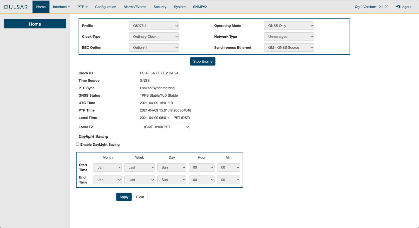
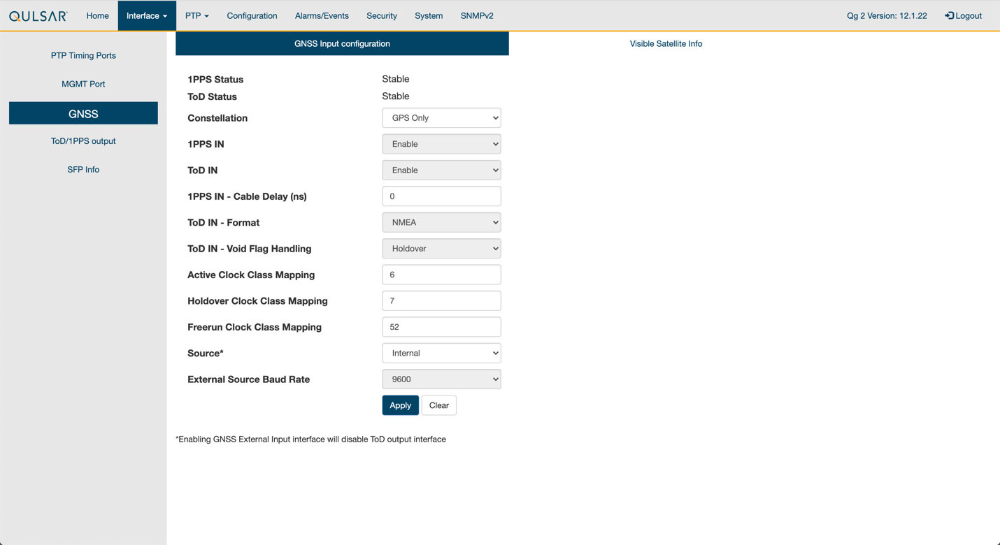
Set the operating mode to GNSS Only, and other fields as such, then run Start Engine
Step 3.
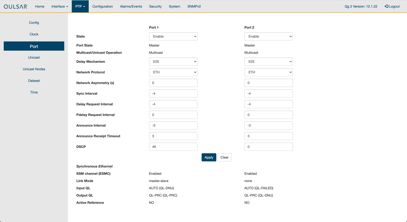
Enable the ports on the GrandMaster with the 8275.1 Profile configurations
Step 4.
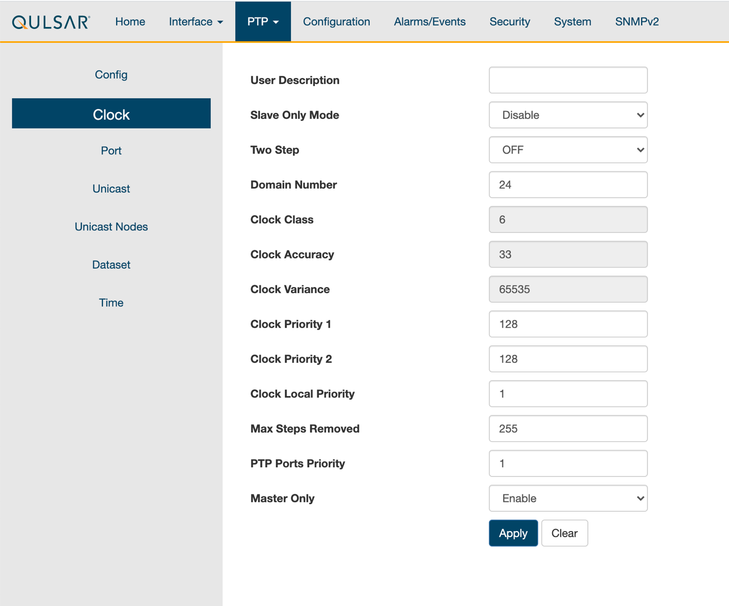
Configure the clock configs as such:
Step 5.
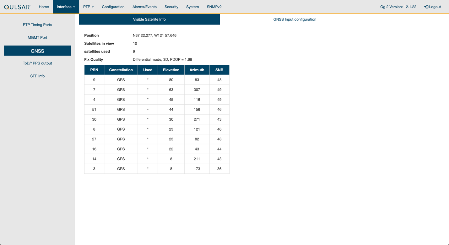
GPS configuration values were unchanged from the default settings of QG2
Step 6.
Verify that the GPS Signal reaches the GrandMaster:
Chapter 2.2 Switch setup
Chapter 2.2.1 Dell Switch
In the following example the RUs are on ports 1 and 7, the GrandMaster is on port 5, the CN is on ports 11 and 12, and the gNB ports are connected to ports 49 and 51 all on vlan 2.
Set up MGMT access to the switch
Enable PTP on the switch:
            OS10# configure terminal

OS10(config)#

ptp clock boundary profile g8275.1

ptp domain 24

ptp system-time enable

!
Configure the GrandMaster port:
            OS10(config)# interface ethernet 1/1/5:1

no shutdown

no switchport

ip address 169.254.2.1/24

flowcontrol receive off

ptp delay-req-min-interval -4

ptp enable

ptp sync-interval -4

ptp transport layer2

!
Configure the other ports (repeat as necessary):
            OS10(config)# interface ethernet1/1/1:1

no shutdown

switchport mode trunk

switchport trunk allowed vlan 2

mtu 8192

flowcontrol receive off

ptp enable

ptp transport layer2

!
Check the PTP status:
            OS10# show ptp | no-more

PTP Clock : Boundary

Clock Identity : b0:4f:13:ff:ff:46:63:5f

GrandMaster Clock Identity : fc:af:6a:ff:fe:02:bc:8d

Clock Mode : One-step

Clock Quality

Class : 135

Accuracy : <=100ns

Offset Log Scaled Variance : 65535

Domain : 24

Priority1 : 128

Priority2 : 128

Profile : G8275-1(Local-Priority:-128)

Steps Removed : 1

Mean Path Delay(ns) : 637

Offset From Master(ns) : 1

Number of Ports : 8

----------------------------------------------------------------------------

Interface State Port Identity

----------------------------------------------------------------------------

Ethernet1/1/1:1 Master b0:4f:13:ff:ff:46:63:5f:1

Ethernet1/1/3:1 Master b0:4f:13:ff:ff:46:63:5f:3

Ethernet1/1/5:1 Slave b0:4f:13:ff:ff:46:63:5f:5

Ethernet1/1/7:1 Master b0:4f:13:ff:ff:46:63:5f:8

Ethernet1/1/11 Master b0:4f:13:ff:ff:46:63:5f:4

Ethernet1/1/49 Master b0:4f:13:ff:ff:46:63:5f:9

Ethernet1/1/51 Master b0:4f:13:ff:ff:46:63:5f:10

Ethernet1/1/54 Master b0:4f:13:ff:ff:46:63:5f:2

----------------------------------------------------------------------------

Number of slave ports :1

Number of master ports :7
Chapter 2.2.2 Fibrolan Falcon RX Setup
Although the Fibrolan switch has not be qualified in NVIDIA lab, OAI labs incorporate the following configuration and switch for interoperability
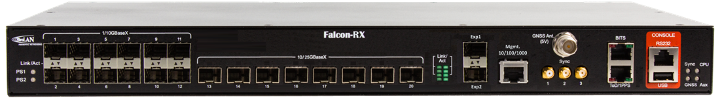
To get started follow the Fibrolan Getting Started Guide.
In our setup the Qulsar GrandMaster is connected to port 4, the Aerial SDK to port 17, and the Foxconn RU to port 16 (C/U plane) and port 15 (S/M plane). You can ignore all other ports in the figures[A][B] below.
VLAN setup
In the following we assume that the VLAN tag for both the control plane and the user plane of the O-RAN CU plane is 2. VLAN 80 is used for everything else.

Figure A - Vlan Setup
Open the configuration page of the Fibrolan switch, go to configuration -> VLANs. Port 4 (the Qulsar GrandMaster) needs to be configured in Access mode using and setting the port VLAN to 80.

Figure B - Vlan Setup
Use the same configuration for port 15 (RU S/M plane).
Ports 16 and 17 need to be configured in Trunk mode, port VLAN 80, Untag Port VLAN, Allowed VLANs 80,2
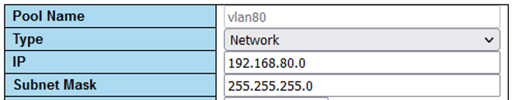
DHCP setup
The RU M-plane requires to setup a DHCP server. Go to Configuration -> DHCP -> server -> pool and create a new DHCP server with the following settings
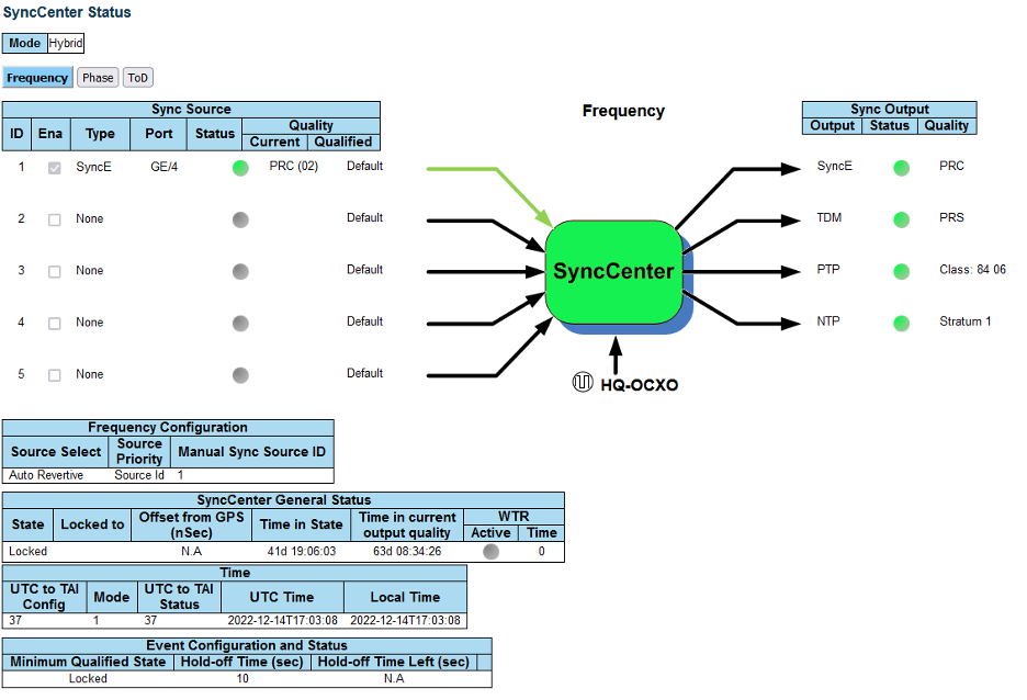
PTP setup
For the PTP setup, first follow the Fibrolan “PTP Boundary Clock Configuration” guide with the following specific settings: • Device Type “Ord-Bound” • Profile “G8275.1” • Clock domain 24 • VLAN 80 Also make sure you enable the used ports (4,15,16,17 in our case)
We also recommend to use “hybrid mode” as sync mode.
If everything is configured correctly, the Sync Center should be green
Chapter 2.3 PTP Setup
Step 1.
Enter these commands to configure PTP4L assuming the ens6f0 NIC interface and CPU core 20 are used for PTP:
            cat <<EOF | sudo tee /etc/ptp.conf
[global]
priority1 128
priority2 128
domainNumber 24
tx_timestamp_timeout 30
dscp_event 46
dscp_general 46
logging_level 6
verbose 1
use_syslog 0
logMinDelayReqInterval 1
[ens6f0]
logAnnounceInterval -3
announceReceiptTimeout 3
logSyncInterval -4
logMinDelayReqInterval -4
delay_mechanism E2E
network_transport L2
EOF

cat <<EOF | sudo tee /lib/systemd/system/ptp4l.service
[Unit]
Description=Precision Time Protocol (PTP) service
Documentation=man:ptp4l

[Service]
Restart=always
RestartSec=5s
Type=simple
ExecStart=taskset -c 20 /usr/sbin/ptp4l -f /etc/ptp.conf

[Install]
WantedBy=multi-user.target
EOF

$ sudo systemctl daemon-reload
$ sudo systemctl restart ptp4l.service
$ sudo systemctl enable ptp4l.service
Step 2.
One server will become the master clock, as shown below:
            $ sudo systemctl status ptp4l.service

• ptp4l.service - Precision Time Protocol (PTP) service
     Loaded: loaded (/lib/systemd/system/ptp4l.service; enabled; vendor preset: enabled)
     Active: active (running) since Thu 2022-02-03 22:41:35 UTC; 4min 47s ago
       Docs: man:ptp4l
   Main PID: 1112 (ptp4l)
      Tasks: 1 (limit: 94582)
     Memory: 904.0K
     CGroup: /system.slice/ptp4l.service
             └─1112 /usr/sbin/ptp4l -f /etc/ptp.conf

Feb 03 22:41:44 dc6-devkit-18 taskset[1112]: ptp4l[135.371]: selected local clock b8cef6.fffe.33fdee as best master
Feb 03 22:41:44 dc6-devkit-18 taskset[1112]: ptp4l[135.371]: assuming the grand master role
Feb 03 22:41:44 dc6-devkit-18 taskset[1112]: ptp4l[135.745]: selected local clock b8cef6.fffe.33fdee as best master
Feb 03 22:41:44 dc6-devkit-18 taskset[1112]: ptp4l[135.745]: assuming the grand master role
Feb 03 22:41:44 dc6-devkit-18 taskset[1112]: ptp4l[135.780]: port 1: link up
Feb 03 22:41:44 dc6-devkit-18 taskset[1112]: ptp4l[135.804]: port 1: FAULTY to LISTENING on INIT_COMPLETE
Feb 03 22:41:44 dc6-devkit-18 taskset[1112]: ptp4l[135.855]: port 1: new foreign master b8cef6.fffe.33fe16-1
Feb 03 22:41:44 dc6-devkit-18 taskset[1112]: ptp4l[136.105]: selected best master clock b8cef6.fffe.33fe16
Feb 03 22:41:44 dc6-devkit-18 taskset[1112]: ptp4l[136.105]: assuming the grand master role
Feb 03 22:41:44 dc6-devkit-18 taskset[1112]: ptp4l[136.105]: port 1: LISTENING to GRAND_MASTER on RS_GRAND_MASTER
Step 3.
The other will become the secondary, follower clock, as shown below:
            $ sudo systemctl status ptp4l.service

• ptp4l.service - Precision Time Protocol (PTP) service
     Loaded: loaded (/lib/systemd/system/ptp4l.service; enabled; vendor preset: enabled)
     Active: active (running) since Thu 2022-02-03 22:41:12 UTC; 5min ago
       Docs: man:ptp4l
   Main PID: 1112 (ptp4l)
      Tasks: 1 (limit: 94582)
     Memory: 812.0K
     CGroup: /system.slice/ptp4l.service
             └─1112 /usr/sbin/ptp4l -f /etc/ptp.conf

Feb 03 22:46:30 dc6-aerial-devkit-17 taskset[1112]: ptp4l[444.474]: rms    5 max   11 freq  +2450 +/-   8 delay   259 +/-   1
Feb 03 22:46:31 dc6-aerial-devkit-17 taskset[1112]: ptp4l[445.475]: rms    5 max   12 freq  +2447 +/-   9 delay   260 +/-   1
Feb 03 22:46:32 dc6-aerial-devkit-17 taskset[1112]: ptp4l[446.475]: rms    6 max   13 freq  +2461 +/-   7 delay   258 +/-   0
Feb 03 22:46:33 dc6-aerial-devkit-17 taskset[1112]: ptp4l[447.475]: rms    5 max   10 freq  +2457 +/-   9 delay   260 +/-   0
Feb 03 22:46:34 dc6-aerial-devkit-17 taskset[1112]: ptp4l[448.475]: rms    3 max    6 freq  +2454 +/-   4 delay   261 +/-   1
Feb 03 22:46:35 dc6-aerial-devkit-17 taskset[1112]: ptp4l[449.475]: rms    4 max    7 freq  +2458 +/-   6 delay   259 +/-   0
Feb 03 22:46:36 dc6-aerial-devkit-17 taskset[1112]: ptp4l[450.475]: rms    4 max    6 freq  +2454 +/-   6 delay   259 +/-   1
Feb 03 22:46:37 dc6-aerial-devkit-17 taskset[1112]: ptp4l[451.475]: rms    4 max    8 freq  +2452 +/-   6 delay   258 +/-   0
Feb 03 22:46:38 dc6-aerial-devkit-17 taskset[1112]: ptp4l[452.475]: rms    3 max    7 freq  +2454 +/-   6 delay   258 +/-   0
Feb 03 22:46:39 dc6-aerial-devkit-17 taskset[1112]: ptp4l[453.475]: rms    6 max   14 freq  +2460 +/-   9 delay   258 +/-   1
Step 4.
Enter the commands to turn off NTP:
            $ sudo timedatectl set-ntp false
$ timedatectl
Local time: Thu 2022-02-03 22:30:58 UTC
           Universal time: Thu 2022-02-03 22:30:58 UTC
                 RTC time: Thu 2022-02-03 22:30:58
                Time zone: Etc/UTC (UTC, +0000)
System clock synchronized: no
              NTP service: inactive
          RTC in local TZ: no
Step 5.
Run PHC2SYS as service:
            # If more than one instance is already running, kill the existing
# PHC2SYS sessions.

# check that the service is active and has low rms value (<30):
$ sudo systemctl status phc2sys.service

• phc2sys.service - Synchronize system clock or PTP hardware clock (PHC)
   Loaded: loaded (/lib/systemd/system/phc2sys.service; disabled; vendor preset: enabled)
   Active: inactive (dead)
     Docs: man:phc2sys
# If the service is already running, then you don't need to change
# anything:
$ sudo systemctl status phc2sys.service

• phc2sys.service - Synchronize system clock or PTP hardware clock (PHC)
     Loaded: loaded (/lib/systemd/system/phc2sys.service; disabled; vendor preset: enabled)
     Active: active (running) since Fri 2021-04-30 14:28:57 UTC; 17s ago
       Docs: man:phc2sys
   Main PID: 1180983 (sh)
      Tasks: 2 (limit: 94582)
     Memory: 2.2M
     CGroup: /system.slice/phc2sys.service
             ├─1180983 /bin/sh -c /usr/sbin/phc2sys -s /dev/ptp$(ethtool -T $(lshw -c network -businfo | grep b5:00.0 | awk '{print $2}') | grep PTP | awk '{print $4}') -c CLOCK_REALTIME -n 24 -O 0 -R 256 -u 256
             └─1181087 /usr/sbin/phc2sys -s /dev/ptp2 -c CLOCK_REALTIME -n 24 -O 0 -R 256 -u 256

Apr 30 14:29:05 aerial-devkit-16 phc2sys[1181087]: [53625.834] CLOCK_REALTIME rms   10 max   24 freq +35384 +/-  42 delay  1769 +/-  11
Apr 30 14:29:06 aerial-devkit-16 phc2sys[1181087]: [53626.850] CLOCK_REALTIME rms    9 max   26 freq +35355 +/-  41 delay  1774 +/-   9
Apr 30 14:29:07 aerial-devkit-16 phc2sys[1181087]: [53627.866] CLOCK_REALTIME rms    8 max   23 freq +35378 +/-  23 delay  1778 +/-   7
Apr 30 14:29:08 aerial-devkit-16 phc2sys[1181087]: [53628.881] CLOCK_REALTIME rms    9 max   22 freq +35358 +/-  26 delay  1761 +/-  13
Apr 30 14:29:09 aerial-devkit-16 phc2sys[1181087]: [53629.897] CLOCK_REALTIME rms    8 max   20 freq +35372 +/-  14 delay  1760 +/-  12
Apr 30 14:29:10 aerial-devkit-16 phc2sys[1181087]: [53630.913] CLOCK_REALTIME rms    9 max   25 freq +35374 +/-  15 delay  1764 +/-  12
Apr 30 14:29:11 aerial-devkit-16 phc2sys[1181087]: [53631.929] CLOCK_REALTIME rms    9 max   21 freq +35371 +/-  21 delay  1759 +/-   8
Apr 30 14:29:12 aerial-devkit-16 phc2sys[1181087]: [53632.945] CLOCK_REALTIME rms    9 max   23 freq +35364 +/-  22 delay  1760 +/-   9
Apr 30 14:29:13 aerial-devkit-16 phc2sys[1181087]: [53633.961] CLOCK_REALTIME rms    9 max   23 freq +35373 +/-  16 delay  1756 +/-   9
Apr 30 14:29:14 aerial-devkit-16 phc2sys[1181087]: [53634.976] CLOCK_REALTIME rms   10 max   24 freq +35354 +/-  33 delay  1757 +/-   9

# Command used can be found in /lib/systemd/system/phc2sys.service
# Update the ExecStart line to the following, assuming ens6f0 interface is used.
$ sudo nano /lib/systemd/system/phc2sys.service

[Unit]
Description=Synchronize system clock or PTP hardware clock (PHC)
Documentation=man:phc2sys
After=ntpdate.service
Requires=ptp4l.service
After=ptp4l.service

[Service]
Restart=always
RestartSec=5s
Type=simple
ExecStart=/bin/sh -c "/usr/sbin/phc2sys -s /dev/ptp$(ethtool -T ens6f0 | grep PTP | awk '{print $4}')-c CLOCK_REALTIME -n 24 -O 0 -R 256 -u 256"

[Install]
WantedBy=multi-user.target

# Once that file is changed, run the following:
$ sudo systemctl daemon-reload
$ sudo systemctl restart phc2sys.service
# Set to start automatically on reboot
$ sudo systemctl enable phc2sys.service

$ sudo systemctl status phc2sys.service

• phc2sys.service - Synchronize system clock or PTP hardware clock (PHC)
     Loaded: loaded (/lib/systemd/system/phc2sys.service; disabled; vendor preset: enabled)
     Active: active (running) since Fri 2021-04-30 14:28:57 UTC; 17s ago
       Docs: man:phc2sys
   Main PID: 1180983 (sh)
      Tasks: 2 (limit: 94582)
     Memory: 2.2M
     CGroup: /system.slice/phc2sys.service
             ├─1180983 /bin/sh -c /usr/sbin/phc2sys -s /dev/ptp$(ethtool -T $(lshw -c network -businfo | grep b5:00.0 | awk '{print $2}') | grep PTP | awk '{print $4}') -c CLOCK_REALTIME -n 24 -O 0 -R 256 -u 256
             └─1181087 /usr/sbin/phc2sys -s /dev/ptp2 -c CLOCK_REALTIME -n 24 -O 0 -R 256 -u 256

Apr 30 14:29:05 aerial-devkit-16 phc2sys[1181087]: [53625.834] CLOCK_REALTIME rms   10 max   24 freq +35384 +/-  42 delay  1769 +/-  11
Apr 30 14:29:06 aerial-devkit-16 phc2sys[1181087]: [53626.850] CLOCK_REALTIME rms    9 max   26 freq +35355 +/-  41 delay  1774 +/-   9
Apr 30 14:29:07 aerial-devkit-16 phc2sys[1181087]: [53627.866] CLOCK_REALTIME rms    8 max   23 freq +35378 +/-  23 delay  1778 +/-   7
Apr 30 14:29:08 aerial-devkit-16 phc2sys[1181087]: [53628.881] CLOCK_REALTIME rms    9 max   22 freq +35358 +/-  26 delay  1761 +/-  13
Apr 30 14:29:09 aerial-devkit-16 phc2sys[1181087]: [53629.897] CLOCK_REALTIME rms    8 max   20 freq +35372 +/-  14 delay  1760 +/-  12
Apr 30 14:29:10 aerial-devkit-16 phc2sys[1181087]: [53630.913] CLOCK_REALTIME rms    9 max   25 freq +35374 +/-  15 delay  1764 +/-  12
Apr 30 14:29:11 aerial-devkit-16 phc2sys[1181087]: [53631.929] CLOCK_REALTIME rms    9 max   21 freq +35371 +/-  21 delay  1759 +/-   8
Apr 30 14:29:12 aerial-devkit-16 phc2sys[1181087]: [53632.945] CLOCK_REALTIME rms    9 max   23 freq +35364 +/-  22 delay  1760 +/-   9
Apr 30 14:29:13 aerial-devkit-16 phc2sys[1181087]: [53633.961] CLOCK_REALTIME rms    9 max   23 freq +35373 +/-  16 delay  1756 +/-   9
Apr 30 14:29:14 aerial-devkit-16 phc2sys[1181087]: [53634.976] CLOCK_REALTIME rms   10 max   24 freq +35354 +/-  33 delay  1757 +/-   9
Step 6.
Verify whether the system clock is synchronized:
            $ timedatectl
Local time: Thu 2022-02-03 22:30:58 UTC
           Universal time: Thu 2022-02-03 22:30:58 UTC
                 RTC time: Thu 2022-02-03 22:30:58
                Time zone: Etc/UTC (UTC, +0000)
System clock synchronized: yes
              NTP service: inactive
          RTC in local TZ: no
Chapter 2.4 Set up the Foxconn ORU
Foxconn RPQN-7801E |
Connections and Settings |
|---|---|
|
Connections:
GrandMaster settings (Qulsar):
/home/root/sdcard/RRHconfig_xran.xml:
|
M-Plane Setup
VLAN setup for the M-Plane connection
Add this to the bottom of /etc/profile and comment out the line with
.``/set_qse.sh`` if there is one.
The interface should be set to eth0 for firmware version 1 and qse-eth for
firmware version ≥ 2
            interface=eth0

vlanid=2

ipLastOctet=20

ip link add link ${interface} name ${interface}.$vlanid type vlan id
$vlanid

ip addr flush dev ${interface}

ip addr add 169.254.0.0/24 dev ${interface}

ip addr add 169.254.1.${ipLastOctet}/24 dev ${interface}.$vlanid

ip link set up ${interface}.$vlanid

# Reboot the RU and check the network configuration:
 # ./reboot.sh
 # ip r

169.254.1.0/24 dev qse-eth.2 src 169.254.1.20
Configure VLAN and IP address on the gNB server
Note:
Add these instructions to server startup script ‘/etc/rc.local’ so they are automatically run on reboot
You should configure this on the fronthaul port
Make sure you use different/unique ip address from the example below
            sudo ip link add link enp181s0f0 name enp181s0f0.2type vlan id2
sudo ip addr add 169.254.1.103/24dev enp181s0f0.2
sudo ip link set up enp181s0f0.2
FW update
Currently to support OAM and M plan over 1G eth port, FW v1_5_15q_524 is required
To upgrade to OAM version, run below in order:
Download the
install_eng_v1_5_15q.524.runandinstall_oam_v1_5_15q.524.runfrom Mantis.Copy the executables to O-RU using below command:
            scp -oCiphers=aes128-ctr
install_eng_v1_5_15q_524.run  root@169.254.1.11:/home/root/test/

scp -oCiphers=aes128-ctr
install_oam_v1_5_15q_524.run  root@169.254.1.11:/home/root/test/
Execute
install_eng_v1_5_15q.524.rununder/home/root/testfirst and waiting for rebooting.Execute install_oam_v1_5_15q.524.run under /home/root/test first and waiting for rebooting.
With above steps, the RU firmware will be upgraded to v1.5.15q.524 and had the OAM packages installed. Run below to check the version:
            root@arria10:~# cat /home/root/test/version.txt
branch: master
version: e93d38e64f83160bf0be31858efedd627dcc8723
tag: v1.5.15q.524
To upgrade FW from v2_2_4q_524 to v2_4_6q_524, run below in order:
Download sw_v2_4_6q_524.zip from Mantis: https://mantis.cnsbg.foxconn.com/faca/view.php?id=488#c4188, unzip it to get install_eng_v2_4_6q_524.run and install_oam_v2_4_6q_524.run
Copy the executables to O-RU using below command(password: e/4g;4uh/6x.6):
            scp -P 830 -oCiphers=aes128-ctr
install_eng_v2_4_6q_524.run  root@169.254.1.11:/home/root/test/

scp -P 830 -oCiphers=aes128-ctr
install_oam_v2_4_6q_524.run  root@169.254.1.11:/home/root/test/
Execute install_eng_v2_4_6q_524.run under /home/root/test and waiting for rebooting.
Execute install_oam_v2_4_6q_524.run under /home/root/test and waiting for rebooting.
With above steps, the RU firmware will be upgraded to v2.4.6q.524 and had the OAM packages installed. Run below to check the version:
            root@ae-oru-2:~/test# cat version.txt
branch: 327-set_trx_switch_to_tx_when_dpd_init_and_reset
version: 91af8c69eeebe1b61bcd9426898dcb87fda5a574
tag: v2.4.6q.524-oam
To upgrade FW from v2_4_6q_524 to v2_6_9q_524, run below in order:
Download install_eng_v2_6_9q_524.run and install_oam_v2_6_9q_524.run from Mantis: https://mantis.cnsbg.foxconn.com/faca/view.php?id=488#c4610
Copy the executables to O-RU using below command(password: e/4g;4uh/6x.6):
            scp -P 830 -oCiphers=aes128-ctr
install_eng_v2_6_9q_524.run  root@169.254.1.11:/home/root/test/
scp -P 830 -oCiphers=aes128-ctr
install_oam_v2_6_9q_524.run  root@169.254.1.11:/home/root/test/
Execute ./install_eng_v2_6_9q_524.run under /home/root/test and waiting for rebooting.
Execute ./install_oam_v2_6_9q_524.run under /home/root/test and waiting for rebooting.
With above steps, the RU firmware will be upgraded to v2.6.9q.524 and had the OAM packages installed. Run below to check the version:
            root@ae-oru-2:~/test# cat version.txt
branch: 328-change_default_clock_out_to_10mhz
version: 60635d6be38bd0480968c344d5ecc3aec1a29fe1
tag: v2.6.9q.524-oam
Update O-RU config in non-OAM mode
Update configurations in /home/root/sdcard/RRHconfig_xran.xml
            | root@arria10:~/test# diff ../sdcard/RRHconfig\_xran.xml
  ../sdcard/RRHconfig\_xran.xml.bak
| --- ../sdcard/RRHconfig\_xran.xml
| +++ ../sdcard/RRHconfig\_xran.xml.bak
| @@ -18,11 +18,11 @@
| <!-- RRH\_CMPR\_HDR\_PRESENT: Indicate the UdCompHdr/reserved field is
  present or not, 0:no present; 1:present -->
| -RRH\_CMPR\_HDR\_PRESENT = 0

| +RRH\_CMPR\_HDR\_PRESENT = 1
| <!-- RRH\_MSGS\_IN\_A\_SYM: Number of messages in a symbol time, (1 or
  2) -->
| -RRH\_MSGS\_IN\_A\_SYM = 1
| +RRH\_MSGS\_IN\_A\_SYM = 2
| <!-- RRH\_CMPR\_TYPE: Indicate compress type. 1st for PDSCH/PUSCH, 2nd
  for PRACH. 0: No Cmpr; 1:block-floating; 2:u-law -->
| -RRH\_CMPR\_TYPE = 1, 1
| +RRH\_CMPR\_TYPE = 0, 0
| <!-- RRH\_CMPR\_BIT\_LENGTH: Indicate the bit length after
  compression. 1st for PDSCH/PUSCH, 2nd for PRACH. -->
| -RRH\_CMPR\_BIT\_LENGTH = 9, 9
| +RRH\_CMPR\_BIT\_LENGTH = 16, 16
| <!-- RRH\_UL\_INIT\_SYM\_ID: Initial symbol ID in UL message -->
| RRH\_UL\_INIT\_SYM\_ID = 0
| <!-- RRH\_TX\_TRUNC\_BITS: The extra truncation in fractional part of
  IFFT output →
| Note: You can add RRH\_DISABLE\_USING\_CAL\_TABLES = YES to the first
  line of RRHconfig\_xran.xml if you want to disable O-RU TX power
  calibration
Reboot O-RU
            cd /home/root/test/

./reboot
Run below to enable the config
            cd /home/root/test/

./init_rrh_config_enable_cuplane
Update network config on DU (aerial-ae-devkit-01):
Check the 10G interface connection of DU over the switch
To figure out what is actually connected, go into switch and run below, and then correlate the network device name on aerial-ae-devkit-01 with that MAC address on port 1/1/49. Answer ens6f0
            OS10# show mac address-table

Codes: pv <vlan-id> - private vlan where the mac is originally learnt

VlanId Mac Address Type Interface

2 6c:ad:ad:00:01:fa dynamic ethernet1/1/2:1

2 6c:ad:ad:00:02:02 dynamic ethernet1/1/1:1

2 b8:ce:f6:95:5f:6c dynamic ethernet1/1/49
Steup the DU 10G interface
At this point, we need to teardown the 1G interface and config the 10G interface on DU:
Note: Add these instructions to system startup script ‘/etc/rc.local’ so that we don’t have to manually run them when there is a reboot
            | sudo ip link add link ens6f0 name ens6f0.2 type vlan id 2
| sudo ip addr add 169.254.1.101/24 dev ens6f0.2
| sudo ip link set up ens6f0.2
Check the 10G M-Plane connection
Ping with the 10G interface to O-RU from DU should be working by now:
            | aerial@aerial-ae-devkit-01:~$ ping 169.254.1.11
| PING 169.254.1.11 (169.254.1.11) 56(84) bytes of data.
| 64 bytes from 169.254.1.11: icmp\_seq=1 ttl=64 time=0.165 ms
| 64 bytes from 169.254.1.11: icmp\_seq=2 ttl=64 time=0.160 ms
| 64 bytes from 169.254.1.11: icmp\_seq=3 ttl=64 time=0.148 ms
Connect O-RU by yangcli from aerial-ae-devkit-01:
yangcli-pro server=169.254.1.11 –ncport=830
user: root
option : 1
password: e/4g;4uh/6x.6
S Plane Setup
Update PTP related configurations
For S Plane over 10G, update below in /home/root/sdcard/RRHconfig_xran.xml
            | <!-- -->
| <!-- PTPV2 Related -->
| <!-- -->
| <!-- RRH\_PTPV2\_GRAND\_MASTER\_MODE: 0: Unicast over 1G, 1:Multicast
  over 1G; 2: Unicast over 10G; 3: Multicast over 10G -->
| RRH\_PTPV2\_GRAND\_MASTER\_MODE = 3
| <!-- RRH\_PTPV2\_JITTER\_LEVEL: The estimated jitter of PTP time
  packets. 0:direct connection to GM/BC, 1:light, 2:medium, 3:heavy -->
| RRH\_PTPV2\_JITTER\_LEVEL = 0
| <!-- RRH\_PTPV2\_VLAN\_ID: VLAN ID of PTPv2. 0/1: No VLAN of
  PTPv2; [2~4092]: valid VLAN of PTPv2; >4092: Invalid and no VLAN will
  be applied -->
| RRH\_PTPV2\_VLAN\_ID = 0
| <!-- RRH\_PTPV2\_GRAND\_MASTER\_IP: IP address of grand-master -->
| RRH\_PTPV2\_GRAND\_MASTER\_IP = 192.167.27.150
| <!-- RRH\_PTPV2\_SUB\_DOMAIN\_NUM: The sub-domain number -->
| RRH\_PTPV2\_SUB\_DOMAIN\_NUM = 24
Check the O-RU PTP status
In the Serial console, we will NOT see below log if ptp is NOT synced(will have to wait for 2min~ before it’s ready):
We can also check ptp service log file: /var/log/rrh_timing_service.log
Debug in non-OAM mode:
Switch to non-OAM mode, update config, reboot and enable C/U plane
            +---------------------------------------------------------------+
| cd /home/root/test && ./set\_oam\_mode -d                     |
|                                                               |
| vi /home/root/sdcard/RRHconfig\_xran.xml                      |
|                                                               |
| cd /home/root/test/ && ./reboot                               |
|                                                               |
| cd /home/root/test/ && ./init\_rrh\_config\_enable\_cuplane   |
+---------------------------------------------------------------+
Below are the configurations we are setting in non-OAM node and the configuration file is /home/root/sdcard/RRHconfig_xran.xml
            +---------------------------------------------+
| 5c5                                         |
|                                             |
| < RRH\_DST\_MAC\_ADDR = b8:ce:f6:95:5f:6c   |
|                                             |
| **---**                                     |
|                                             |
| > RRH\_DST\_MAC\_ADDR = 00:11:22:33:44:66   |
|                                             |
| 7c7                                         |
|                                             |
| < RRH\_SRC\_MAC\_ADDR = 6C:AD:AD:00:02:02   |
|                                             |
| **---**                                     |
|                                             |
| > RRH\_SRC\_MAC\_ADDR = aa:bb:cc:dd:ee:ff   |
|                                             |
| 15c15                                       |
|                                             |
| < RRH\_TRX\_EN\_BIT\_MASK = 0x03            |
|                                             |
| **---**                                     |
|                                             |
| > RRH\_TRX\_EN\_BIT\_MASK = 0x0f            |
|                                             |
| 17c17                                       |
|                                             |
| < RRH\_RF\_EN\_BIT\_MASK = 0x03             |
|                                             |
| **---**                                     |
|                                             |
| > RRH\_RF\_EN\_BIT\_MASK = 0x0f             |
|                                             |
| 19c19                                       |
|                                             |
| < RRH\_CMPR\_HDR\_PRESENT = \ **0**         |
|                                             |
| **---**                                     |
|                                             |
| > RRH\_CMPR\_HDR\_PRESENT = \ **1**         |
|                                             |
| 23c23                                       |
|                                             |
| < RRH\_CMPR\_TYPE = 1, \ **1**              |
|                                             |
| **---**                                     |
|                                             |
| > RRH\_CMPR\_TYPE = 0, \ **0**              |
|                                             |
| 25c25                                       |
|                                             |
| < RRH\_CMPR\_BIT\_LENGTH = 9, \ **9**       |
|                                             |
| **---**                                     |
|                                             |
| > RRH\_CMPR\_BIT\_LENGTH = 16, \ **16**     |
|                                             |
| 35c35                                       |
|                                             |
| < RRH\_C\_PLANE\_VLAN\_TAG = 0x0002         |
|                                             |
| **---**                                     |
|                                             |
| > RRH\_C\_PLANE\_VLAN\_TAG = 0xe001         |
|                                             |
| 37c37                                       |
|                                             |
| < RRH\_U\_PLANE\_VLAN\_TAG = 0x0002         |
|                                             |
| **---**                                     |
|                                             |
| > RRH\_U\_PLANE\_VLAN\_TAG = 0xe002         |
|                                             |
| 43c43                                       |
|                                             |
| < RRH\_LO\_FREQUENCY\_KHZ = \ **3750000**   |
|                                             |
| **---**                                     |
|                                             |
| > RRH\_LO\_FREQUENCY\_KHZ = \ **3749700**   |
+---------------------------------------------+
For parameters that are not supported in OAM mode, need to set them in RRHconfig_xran_default.xml beforehand:
            ssh -p 830 \ root@169.254.1.12

vi /home/root/sdcard/RRHconfig\_xran\_default.xml
Below parameters are not supported in OAM mode at the moment:
            +---------------------------------------+
| 15c15                                 |
|                                       |
| < RRH\_TRX\_EN\_BIT\_MASK = 0x03      |
|                                       |
| **---**                               |
|                                       |
| > RRH\_TRX\_EN\_BIT\_MASK = 0x0f      |
|                                       |
| 17c17                                 |
|                                       |
| < RRH\_RF\_EN\_BIT\_MASK = 0x03       |
|                                       |
| **---**                               |
|                                       |
| > RRH\_RF\_EN\_BIT\_MASK = 0x0f       |
|                                       |
| 19c19                                 |
|                                       |
| < RRH\_CMPR\_HDR\_PRESENT = \ **0**   |
|                                       |
| **---**                               |
|                                       |
| > RRH\_CMPR\_HDR\_PRESENT = \ **1**   |
+---------------------------------------+
Reference O-RU configuration file
Reference RRHconfig_xran.xml
+----------------------------------------------------------------------------------------------------------------------------------------------------------+
| <!-- --> |
| |
| <!-- Common --> |
| |
| <!-- --> |
| |
| <!-- RRH\_DST\_MAC\_ADDR: Destination MAC address, fill with 6 bytes and separate each others by colon --> |
| |
| RRH\_DST\_MAC\_ADDR = 00:11:22:33:44:66 |
| |
| <!-- RRH\_SRC\_MAC\_ADDR: Source MAC address, fill with 6 bytes and separate each others by colon --> |
| |
| RRH\_SRC\_MAC\_ADDR = 6c:ad:ad:00:01:5c |
| |
| <!-- RRH\_RU\_PORT\_ID: RRH RU PORT ID, fill with 4 bytes and separate each others by common and space --> |
| |
| RRH\_RU\_PORT\_ID = 0, 1, 2, \ **3** |
| |
| <!-- RRH\_EN\_SPC: Enable SPC or not, 0:OFF, 1:ON --> |
| |
| RRH\_EN\_SPC = \ **1** |
| |
| <!-- RRH\_RRH\_LTE\_OR\_NR: Indicate the spec of xRAN, 0:LTE, 1:NR --> |
| |
| RRH\_RRH\_LTE\_OR\_NR = \ **1** |
| |
| <!-- RRH\_TRX\_EN\_BIT\_MASK: Bit-mask of 4 TRx, bit 0: TRx0, bit1: TRx1, bit2: TRx2, bit3: TRx3 --> |
| |
| RRH\_TRX\_EN\_BIT\_MASK = 0x03 |
| |
| <!-- RRH\_RF\_EN\_BIT\_MASK: Bit-mask of 4 PA/LNA, bit0: PA0/LNA0, bit1: PA1/LNA1, bit2: PA2/LNA2, bit3: PA3/LNA3 --> |
| |
| RRH\_RF\_EN\_BIT\_MASK = 0x03 |
| |
| <!-- RRH\_CMPR\_HDR\_PRESENT: Indicate the UdCompHdr/reserved field is present or not, 0:no present; 1:present --> |
| |
| RRH\_CMPR\_HDR\_PRESENT = \ **0** |
| |
| <!-- RRH\_MSGS\_IN\_A\_SYM: Number of messages in a symbol time, (1 or 2) --> |
| |
| RRH\_MSGS\_IN\_A\_SYM = \ **1** |
| |
| <!-- RRH\_CMPR\_TYPE: Indicate compress type. 1st for PDSCH/PUSCH, 2nd for PRACH. 0: No Cmpr; 1:block-floating; 2:u-law --> |
| |
| RRH\_CMPR\_TYPE = 1, \ **1** |
| |
| <!-- RRH\_CMPR\_BIT\_LENGTH: Indicate the bit length after compression. 1st for PDSCH/PUSCH, 2nd for PRACH. --> |
| |
| RRH\_CMPR\_BIT\_LENGTH = 9, \ **9** |
| |
| <!-- RRH\_UL\_INIT\_SYM\_ID: Initial symbol ID in UL message --> |
| |
| RRH\_UL\_INIT\_SYM\_ID = \ **0** |
| |
| <!-- RRH\_TX\_TRUNC\_BITS: The extra truncation in fractional part of IFFT output --> |
| |
| RRH\_TX\_TRUNC\_BITS = \ **4** |
| |
| <!-- RRH\_RX\_TRUNC\_BITS: The extra truncation in fractional part of FFT output --> |
| |
| RRH\_RX\_TRUNC\_BITS = \ **4** |
| |
| <!-- RRH\_MAX\_PRB: Maximum PRBs --> |
| |
| RRH\_MAX\_PRB = \ **273** |
| |
| <!-- RRH\_C\_PLANE\_VLAN\_TAG: C-plane V-LAN tag express by hex number --> |
| |
| RRH\_C\_PLANE\_VLAN\_TAG = 0x0002 |
| |
| <!-- RRH\_U\_PLANE\_VLAN\_TAG: U-plane V-LAN tag express by hex number --> |
| |
| RRH\_U\_PLANE\_VLAN\_TAG = 0x0002 |
| |
| <!-- RRH\_SLOT\_TICKS\_IN\_SEC: Number of slot tick in a second (2000 slots for u=1) --> |
| |
| RRH\_SLOT\_TICKS\_IN\_SEC = \ **2000** |
| |
| <!-- RRH\_SLOT\_PERIOD\_IN\_SAMPLE: Slot period in 122.88MHz (61440 for u=1) --> |
| |
| RRH\_SLOT\_PERIOD\_IN\_SAMPLE = \ **61440** |
| |
| <!-- RRH\_LO\_FREQUENCY\_KHZ: Tx and Rx PLL LO Frequency in kHz(internal or external LO) --> |
| |
| RRH\_LO\_FREQUENCY\_KHZ = \ **3750000** |
| |
| <!-- RRH\_TX\_ATTENUATION: Tx attenuation value with 1-digit fraction for each layer (>10dB. NOTE: The attenuation value must be larget than 10dB) --> |
| |
| RRH\_TX\_ATTENUATION = 30.0, 30.0, 30.0, 30.0 |
| |
| <!-- RRH\_RX\_ATTENUATION: Rx attenuation value with 1-digit fraction for each layer (<30dB) --> |
| |
| RRH\_RX\_ATTENUATION = 20.0, 20.0, 20.0, 20.0 |
| |
| <!-- RRH\_BB\_GENERAL\_CTRL: General control words for Baseband --> |
| |
| <!-- Bit[0] of 1st word: Enable the filtering of MAC address --> |
| |
| <!-- Bit[1] of 1st word: Enable the UL slot tick packets per port --> |
| |
| <!-- Others: Reserved --> |
| |
| RRH\_BB\_GENERAL\_CTRL = 0x0, 0x0, 0x0, 0x0 |
| |
| <!-- RRH\_RF\_GENERAL\_CTRL: General control words for RF --> |
| |
| <!-- Bit[0] of 4th word: 1=for N77, 0=else --> |
| |
| RRH\_RF\_GENERAL\_CTRL = 0x0, 0x0, 0x0, 0x0 |
| |
| <!-- --> |
| |
| <!-- PTPV2 Related --> |
| |
| <!-- --> |
| |
| <!-- RRH\_PTPV2\_GRAND\_MASTER\_MODE: 0: Unicast, 1:Multicast --> |
| |
| RRH\_PTPV2\_GRAND\_MASTER\_MODE = \ **1** |
| |
| <!-- RRH\_PTPV2\_OBSERVATION\_TIME: 0: Stop xRAN immediately when OOL; >0: Stop xRAN after specific seconds when OOL --> |
| |
| RRH\_PTPV2\_OBSERVATION\_TIME = \ **10000** |
| |
| <!-- RRH\_PTPV2\_GRAND\_MASTER\_IP: IP address of grand-master --> |
| |
| RRH\_PTPV2\_GRAND\_MASTER\_IP = 192.168.3.150 |
| |
| <!-- RRH\_PTPV2\_SUB\_DOMAIN\_NUM: The sub-domain number --> |
| |
| RRH\_PTPV2\_SUB\_DOMAIN\_NUM = \ **24** |
+----------------------------------------------------------------------------------------------------------------------------------------------------------+
This section describes how to setup the Aerial private 5G network which consists of:
Aerial SDK L1
Remaining components of OAI gNB
OAI Core Network
User Equipment (UE)
Edge Server Applications(e.g. iPerf)
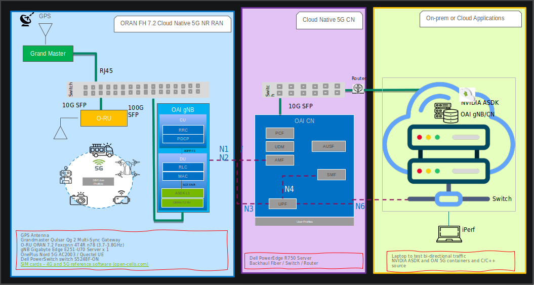
These instructions assume that the core network and gNB can be deployed on the same host server.
Software Release Manifest
| Component | Version |
| Aerial SDK (ASDK) PHY | 22.2.2 |
| OAI gNB | 2022.w50 |
| OAI CN | 1.4.0 |
Setup Aerial SDK L1
Please follow the step by step installation guide for cuBB located at NVIDIA Developer Zone - Aerial SDK https://developer.nvidia.com/docs/gputelecom/aerial-sdk/text/cubb_install/index.html
cuBB Installation Guide: From System Requirements to Troubleshooting**()
Since cuBB 22.2.2 release, the test vectors are not included in the SDK. The developer needs to generate the TV files first before running cuPHY examples or cuBB end-to-end test.
Using Aerial Python mcore Module
No Matlab license required to generate TV files using Aerial Python mcore module. The cuBB Container already has aerial_mcore installed. To generate the TV files, run the following commands inside the Aerial container.
The TV generation may take few hours on the devkit with current isocpus parameter setting in kernel command line. Please also ensure the host has sufficient space to contain 111GB of TV files.
            cd ${cuBB_SDK}/5GModel/aerial_mcore/examples
source ../scripts/setup.sh
export REGRESSION_MODE=1
time python3 ./example_5GModel_regression.py allChannels
echo $?
ls -alF GPU_test_input/
du -h GPU_test_input/
Example output is shown below. The “real” time takes less than one hour on a 24 cores x86 host. The “echo $?” shows the exit code of the process, which should be 0. A non-zero exit code indicates a failure.
            Channel  Compliance_Test  Error   Test_Vector  Error  Performance_Test   Fail
------------------------------------------------------------------------------
SSB           37            0         42          0           0            0
PDCCH         71            0         80          0           0            0
PDSCH        274            0        286          0           0            0
CSIRS         86            0         87          0           0            0
DLMIX          0            0        1049          0           0            0
PRACH         60            0         60          0          48            0
PUCCH        469            0        469          0          96            0
PUSCH        388            0        398          0          41            0
SRS          125            0        125          0           0            0
ULMIX          0            0        576          0           0            0
BFW           58            0         58          0           0            0
------------------------------------------------------------------------------
Total       1568            0       3230          0         185            0

Total time for runRegression is 2147 seconds
Parallel pool using the 'local' profile is shutting down.

real    36m51.931s
user    585m1.704s
sys     10m28.322s
To Generate the launch pattern for each test case using cubb_scripts:
            cd $cuBB_SDK
cd cubb_scripts
python3 auto_lp.py -i ../5GModel/aerial_mcore/examples/GPU_test_input -t launch_pattern_nrSim.yaml
Then Copy the launch pattern and TV files to testVectors repo.
            cd $cuBB_SDK
cp ./5GModel/aerial_mcore/examples/GPU_test_input/TVnr_* ./testVectors/.
cp ./5GModel/aerial_mcore/examples/GPU_test_input/launch_pattern* ./testVectors/multi-cell/.
Using Matlab
To generate TV files using Matlab, run the following command in Matlab:
cd('nr_matlab'); startup; [nTC, errCnt] = runRegression({'TestVector'}, {'allChannels'}, 'compact', [0, 1] );
All the cuPHY TVs are generated and stored under nr_matlab/GPU_test_input.
Generate the launch pattern for each test case using cubb_scripts:
            cd $cuBB_SDK
cd cubb_scripts
python3 auto_lp.py -i ../5GModel/nr_matlab/GPU_test_input -t launch_pattern_nrSim.yaml
Copy the launch pattern and TV files to testVectors repo.
            cd $cuBB_SDK
cp ./5GModel/nr_matlab/GPU_test_input/TVnr_* ./testVectors/.
cp ./5GModel/nr_matlab/GPU_test_input/launch_pattern* ./testVectors/multi-cell/.
PTP slave setup Please refer to installation instructions at Installing Tools — Aerial SDK 22-2.2 documentation (nvidia.com)
Setup OAI gNB
Install Ubuntu on both servers
https://releases.ubuntu.com/20.04.4/ubuntu-20.04.4-desktop-amd64.iso
Run the following:
            sudo apt update
sudo apt dist-upgrade
sudo apt autoremove
Prepare gNB docker images
Build gNB docker image
Check out the OpenAirInterface5G repository
            git clone https://gitlab.eurecom.fr/rssilva/openairinterface5g.git

cd openairinterface5g

git checkout FAPI-Improvements
Build the docker image
docker build . -f docker/Dockerfile.aerial.ubuntu20
gNB configuration file
vnf.sa.band78.fr1.273PRB.Aerial.conf
What parameters need to be changed by the user?
TBD - docker-compose yaml file and an entrypoint script for the docker container(targeted in next release)
Setup OAI CN5G
Do this iptables setup below every time after a system reboot. It is also possible to make this permanent in Ubuntu system configuration.
            On CN5G server, configure it to allow the traffic coming in by
adding this rule to iptables:

# On CN5G, upon startup:

sudo sysctl net.ipv4.conf.all.forwarding=1
sudo iptables -P FORWARD ACCEPT
Install the core network by following these steps:
The user configurable configuration files are:
~/oai-cn5g-fed/docker-compose/docker-compose-basic-nrf.yaml
~/oai-cn5g-fed/docker-compose/database/oai_db.sql
Configuring OAI gNB and CN5G
For the purpose of understanding which address is what in the example configuration setting and commands below, we will assume the gNB and CN5G servers have these interface names and IP addresses.
CN5G Server
            eno1: 10.31.66.x            = SSH management port for terminal

eno2: 169.254.200.6         = BH connection on SFP switch for gNB-CN5G traffic
gNB Server
            eno1:     10.31.66.x        = SSH management port for terminal

ens6f0:   b8:ce:f6:4e:75:40 = FH MAC address

ens6f0.2: 169.254.1.105     = FH IP address

ens6f1:   169.254.200.5     = BH connection SFP switch for gNB-CN5G traffic
gNB to set static route
On the gNB server, add this static route for a path to the CN5G server. Please apply this route each time after the server power-on.
            Syntax:
sudo ip route add 192.168.70.128/26 via <CN5G IP> dev <gNB interface for CN5G>

Example:
sudo ip route add 192.168.70.128/26 via 169.254.200.6 dev ens6f1
gNB to set the CN5G server to uses for AMF
Edit gNB configuration file: targets/PROJECTS/GENERIC-NR-5GC/CONF/vnf.sa.band78.fr1.273PRB.Aerial.conf
Below is an example with lab-specific network parameters. Your IP address and interface names may differ.
            GNB_INTERFACE_NAME_FOR_NG_AMF = "ens6f1";       # gNB side interface name of the SFP port toward CN (was eno1)

GNB_IPV4_ADDRESS_FOR_NG_AMF = "169.254.200.5";  # gNB side IP address of interface above (was 172.21.16.130)

GNB_INTERFACE_NAME_FOR_NGU = "ens6f1";          # gNB side interface name of the SFP port toward CN (was eno1)

GNB_IPV4_ADDRESS_FOR_NGU = "169.254.200.5";     # Same IP as GNB_IPV4_ADDRESS_FOR_NG_AMF above (was 172.21.16.130)
Remove SD parameter from gNB configuration file
In the same gNB configuration file, if this line “sd = 0x1” exist, please delete this line when using the latest CN5G.
            plmn_list = ({
              mcc = 001;
              mnc = 01;
              mnc_length = 2;
              snssaiList = (
                {
                  sst = 1;
                  sd  = 0x1; // 0 false, else true
                }
              );
              });
Running CN5G
To start CN5G
            cd ~/oai-cn5g-fed/docker-compose
python3 core-network.py --type start-basic --scenario 1
Or alternatively:
docker-compose up -d
To Stop CN5G
            cd ~/oai-cn5g-fed/docker-compose
python3 core-network.py --type stop-basic --scenario 1
Or alternatively:
docker-compose down
To monitor CN5G logs while running
docker logs oai-amf -f
To capture PCAPs
            docker exec -it oai-amf /bin/bash
apt update && apt install tcpdump -y
tcpdump -i any -w /tmp/amf.pcap
Then we can copy the pcap out from the container
docker cp oai-amf:/tmp/amf.pcap .
Example Screenshot of Starting CN5G
            aerial@:~/oai-cn5g-fed/docker-compose$ python3 core-network.py --type start-basic --scenario 1
[2022-11-16 01:17:22,058] root:DEBUG:  Starting 5gcn components... Please wait....
[2022-11-16 01:17:22,058] root:DEBUG: docker-compose -f docker-compose-basic-nrf.yaml up -d
Creating network "demo-oai-public-net" with driver "bridge"
Pulling mysql (mysql:5.7)...
Creating oai-nrf ... done
Creating mysql   ... done
Creating oai-udr ... done
Creating oai-udm ... done
Creating oai-ausf ... done
Creating oai-amf  ... done
Creating oai-smf  ... done
Creating oai-spgwu ... done
Creating oai-ext-dn ... done
5.7: Pulling from library/mysql
Digest: sha256:0e3435e72c493aec752d8274379b1eac4d634f47a7781a7a92b8636fa1dc94c1
Status: Downloaded newer image for mysql:5.7
[2022-11-16 01:17:35,693] root:DEBUG:  OAI 5G Core network started, checking the health status of the containers... takes few secs....
[2022-11-16 01:17:35,693] root:DEBUG: docker-compose -f docker-compose-basic-nrf.yaml ps -a
[2022-11-16 01:17:48,674] root:DEBUG:  All components are healthy, please see below for more details....
Name                 Command                  State                  Ports
-----------------------------------------------------------------------------------------
mysql        docker-entrypoint.sh mysqld      Up (healthy)   3306/tcp, 33060/tcp
oai-amf      /bin/bash /openair-amf/bin ...   Up (healthy)   38412/sctp, 80/tcp, 9090/tcp
oai-ausf     /bin/bash /openair-ausf/bi ...   Up (healthy)   80/tcp
oai-ext-dn   /bin/bash -c  ip route add ...   Up (healthy)
oai-nrf      /bin/bash /openair-nrf/bin ...   Up (healthy)   80/tcp, 9090/tcp
oai-smf      /bin/bash /openair-smf/bin ...   Up (healthy)   80/tcp, 8080/tcp, 8805/udp
oai-spgwu    /bin/bash /openair-spgwu-t ...   Up (healthy)   2152/udp, 8805/udp
oai-udm      /bin/bash /openair-udm/bin ...   Up (healthy)   80/tcp
oai-udr      /bin/bash /openair-udr/bin ...   Up (healthy)   80/tcp
[2022-11-16 01:17:48,674] root:DEBUG:  Checking if the containers are configured....
[2022-11-16 01:17:48,674] root:DEBUG:  Checking if AMF, SMF and UPF registered with nrf core network....
[2022-11-16 01:17:48,674] root:DEBUG: curl -s -X GET http://192.168.70.130/nnrf-nfm/v1/nf-instances?nf-type="AMF" | grep -o "192.168.70.132"
192.168.70.132
[2022-11-16 01:17:48,692] root:DEBUG: curl -s -X GET http://192.168.70.130/nnrf-nfm/v1/nf-instances?nf-type="SMF" | grep -o "192.168.70.133"
192.168.70.133
[2022-11-16 01:17:48,708] root:DEBUG: curl -s -X GET http://192.168.70.130/nnrf-nfm/v1/nf-instances?nf-type="UPF" | grep -o "192.168.70.134"
192.168.70.134
[2022-11-16 01:17:48,718] root:DEBUG:  Checking if AUSF, UDM and UDR registered with nrf core network....
[2022-11-16 01:17:48,718] root:DEBUG: curl -s -X GET http://192.168.70.130/nnrf-nfm/v1/nf-instances?nf-type="AUSF" | grep -o "192.168.70.138"
192.168.70.138
[2022-11-16 01:17:48,733] root:DEBUG: curl -s -X GET http://192.168.70.130/nnrf-nfm/v1/nf-instances?nf-type="UDM" | grep -o "192.168.70.137"
192.168.70.137
[2022-11-16 01:17:48,747] root:DEBUG: curl -s -X GET http://192.168.70.130/nnrf-nfm/v1/nf-instances?nf-type="UDR" | grep -o "192.168.70.136"
192.168.70.136
[2022-11-16 01:17:48,758] root:DEBUG:  AUSF, UDM, UDR, AMF, SMF and UPF are registered to NRF....
[2022-11-16 01:17:48,758] root:DEBUG:  Checking if SMF is able to connect with UPF....
[2022-11-16 01:17:48,829] root:DEBUG:  UPF did answer to N4 Association request from SMF....
[2022-11-16 01:17:48,866] root:DEBUG:  SMF receiving heathbeats from UPF....
[2022-11-16 01:17:48,867] root:DEBUG:  OAI 5G Core network is configured and healthy....


aerial@:~/oai-cn5g-fed/docker-compose$ docker ps
CONTAINER ID   IMAGE                    COMMAND                  CREATED              STATUS                        PORTS                          NAMES
c6a7eca08187   trf-gen-cn5g:latest      "/bin/bash -c ' ip r…"   About a minute ago   Up About a minute (healthy)                                  oai-ext-dn
5fa931ffb5f1   oai-spgwu-tiny:develop   "/bin/bash /openair-…"   About a minute ago   Up About a minute (healthy)   2152/udp, 8805/udp             oai-spgwu
70b48ac70b63   oai-smf:develop          "/bin/bash /openair-…"   About a minute ago   Up About a minute (healthy)   80/tcp, 8080/tcp, 8805/udp     oai-smf
f18566936f62   oai-amf:develop          "/bin/bash /openair-…"   About a minute ago   Up About a minute (healthy)   80/tcp, 9090/tcp, 38412/sctp   oai-amf
a75c40af3268   oai-ausf:develop         "/bin/bash /openair-…"   About a minute ago   Up About a minute (healthy)   80/tcp                         oai-ausf
a3d796819591   oai-udm:develop          "/bin/bash /openair-…"   About a minute ago   Up About a minute (healthy)   80/tcp                         oai-udm
5442e9a1a2d8   oai-udr:develop          "/bin/bash /openair-…"   About a minute ago   Up About a minute (healthy)   80/tcp                         oai-udr
7bfb07becff3   mysql:5.7                "docker-entrypoint.s…"   About a minute ago   Up About a minute (healthy)   3306/tcp, 33060/tcp            mysql
ea55f52bfcc6   oai-nrf:develop          "/bin/bash /openair-…"   About a minute ago   Up About a minute (healthy)   80/tcp, 9090/tcp               oai-nrf
Step 1: Add the SIM User Profile
Modify:
oai_db.sql (with plain text editor)
There are currently 3 UEs pre-configured here, just search for: 001010000000001 and you will find them, add/edit as needed.
docker-compose-basic-nrf.yaml
MCC, MNC, OPERATOR_KEY (you need to change them in several places)
On gNB server, change the MCC and MNC in the gNB config file ./targets/PROJECTS/GENERIC-NR-5GC/CONF/vnf.sa.band78.fr1.273PRB.Aerial.conf
            plmn_list = ({
- mcc = 208;
- mnc = 98;
+ mcc = 001;
+ mnc = 01;
mnc_length = 2;
Step 2: Setup the UE and SIM Card
For reference, please use the following
*SIM cards – 4G and 5G reference software (open-cells.com)*
Program SIM Card with Open Cells Project application “uicc-v2.6” https://open-cells.com/d5138782a8739209ec5760865b1e53b0/uicc-v2.6.tgz
Use the ADM code specific to the SIM card. If wrong ADM is used for 8 times, the SIM card will be permanently locked.
            sudo ./program_uicc --adm 12345678 --imsi 001010000000001 --isdn 00000001 --acc 0001 --key fec86ba6eb707ed08905757b1bb44b8f --opc C42449363BBAD02B66D16BC975D77CC1 -spn "OpenAirInterface" --authenticate
Existing values in USIM
ICCID: 89860061100000000191
WARNING: iccid luhn encoding of last digit not done
USIM IMSI: 208920100001191
USIM MSISDN: 00000191
USIM Service Provider Name: OpenCells191
Setting new values
Reading UICC values after uploading new values
ICCID: 89860061100000000191
WARNING: iccid luhn encoding of last digit not done
USIM IMSI: 001010000000001
USIM MSISDN: 00000001
USIM Service Provider Name: OpenAirInterface
Succeeded to authentify with SQN: 64
set HSS SQN value as: 96
CUE Configuration Setup
Install the “Magic IPERF” application on the UE:
To test with CUE, a test SIM card with Milenage support is required. The following has to be provisioned on the SIM and it has to match the Core Network settings: mcc, mnc, IMSI, Ki, OPc
The APN on the CUE should be configured according to Core Network settings.
Start the DNS (Core network should assign mobile IP address and DNS. If DNS is not assigned, set DNS with other Android app.)
Step 3. Running End-to-End OTA
This section describes how to run end to end traffic from UE to the edge core network.
Start OAI CN5G Core Network
Start CN5G Network
            sudo sysctl net.ipv4.conf.all.forwarding=1
sudo iptables -P FORWARD ACCEPT

cd ~/oai-cn5g-fed/docker-compose
python3 core-network.py --type start-basic --scenario 1
Start CN5G Edge Application
After the CN5G is started, we can use oai-ext-dn container to run IPERF
docker exec -it oai-ext-dn /bin/bash
Start NVIDIA Aerial cuBB on the gNB
            # Run on host: start a docker terminal
docker exec -it cuBB /bin/bash


# Run in docker container
export CUDA_DEVICE_MAX_CONNECTIONS=16
$cuBB_SDK/build/cuPHY-CP/cuphycontroller/examples/cuphycontroller P5G

# Wait until see console log

====> PhyDriver initialized!

16:29:35.913840 C [NVIPC:DEBUG] ipc_debug_open: pcap enabled:
fapi_type=1 fapi_tb_loc=1

16:29:36.141657 C [NVIPC:SHM] shm_ipc_open: forward_enable=0
fw_max_msg_buf_count=0 fw_max_data_buf_count=0

16:29:36.153808 C [CTL.SCF] cuPHYController configured for 1 cells
16:29:36.153816 C [CTL.SCF]

====> cuPHYController initialized, L1 is ready!
Start OAI gNB L2 Stack on the gNB
Start up the OAI container:
            docker run -dP --privileged  --ipc container:c_aerial_aerial \
      --gpus all --network host --shm-size=4096m  -it \
      -v /lib/modules:/lib/modules \
      -v /dev/hugepages:/dev/hugepages \
      -v /usr/src:/usr/src \
      -v ~/openairinterface5g:/opt/oai/ \
      -v ~/share:/opt/nvidia/cuBB/share \
         --cpuset-cpus=6-13\
         --name i_oai_aerial c_oai_aerial:latest
Then start the OAI nr-softmodem, enter the the container to run the using the configuration file mounted from the host
            docker exec -it  i_oai_aerial bash
# cd to the openairinterface directory
source oaienv
cd cmake_targets/ran_build/build/
./nr-softmodem -O ../../../targets/PROJECTS/GENERIC-NR-5GC/CONF/vnf.sa.band78.fr1.273PRB.Aerial.conf --nfapi aerial --sa
To stop the container:
            docker stop i_oai_aerial
docker rm i_oai_aerial
CUE Connecting to 5G Network
Take the CUE out of Airplane mode to start the UE attaching to the network.
Observe 5G Connect Status
See Preamble log in cuphycontroller console output.
Check Core Network log or CUE log to see whether NAS authentication and PDU session succeed.
Running E2E IPERF Traffic
Start ping, iperf or other network app tests after PDU session connected successfully.
One can install and run “Magic IPerf” Android application on the CUE for this purpose.
IPERF Downlink Test
UE Side:
iperf -s -u -i 1 -B 12.1.1.2
CN5G Side:
docker exec -it oai-ext-dn iperf -u -t 360 -i 1 -fk -B 192.168.70.135 -b 4M -c 12.1.1.2
IPERF Uplink Test
CN5G Side:
docker exec -it oai-ext-dn iperf -s -u -i 1 -B 192.168.70.135
UE Side:
iperf -u -t 360 -i 1 -fk -b 20M -c 192.168.70.135 -B 12.1.1.2