Cooling and Airflow Optimization#
This documentation is part of NVIDIA DGX SuperPOD: Data Center Design Featuring NVIDIA DGX H100 Systems.
It is critical to plan for the full heat load of the rack profiles, keeping in mind that the power provisioning is based on circuits that provide only 50% of the full load. With traditional 2N redundant power provisioning schemes, the cooling capacity is generally aligned with the capacity of N, but N is usually the capacity of a single power circuit. However, with the specified N+1 power provisioning, N equals two circuits. Therefore, it is critical to align the cooling capacity with N, and not simply the capacity of a single power circuit. Some data center designs may have constraints on cooling capacity that will require mitigation as part of the DGX SuperPOD deployment plan. The following sections reveal common strategies for mitigating these constraints.
Use this documentation to learn about the following:
Foundational Concepts#
Before considering more drastic cooling mitigations, it is important to make sure that the airflow in the space is optimized and well managed. While the following steps may be rudimentary, their importance cannot be overstated.
Row Orientation#
The rows of racks on a data center floor are usually arranged in such a way as to create a hot aisle and a cold aisle. These aisles are created by orienting the racks so that the backs of two opposing rows of racks face one another in one aisle, and the fronts of two rows of racks face each other in the next aisle. Supply air is delivered to the “cold aisle,” and exhaust air is evacuated from the “hot aisle.” It is important to space these rows carefully, so that the width of the cold aisle is sufficient to deliver the required volume of air for all the racks it serves, and the width of the hot aisle is sufficient to prevent racks with higher powered servers from interfering with the exhaust airflow from lower powered servers in the opposing row. At a minimum, the aisles should be at least 36 inches wide, and it is strongly recommended that the cold aisle be a minimum of 48 inches wide, to allow for the safe navigation and use of server lifts, technical carts, and other conveyances within the aisle.
Aisle Containment#
Many data centers employ aisle containment strategies to help manage and optimize airflow, particularly for high-density racks. Data Center designers may choose to contain either the cold aisle or the hot aisle depending on the means of air delivery in a data center space. In either case, the main benefit of aisle containment is the prevention of air recirculation from the hot aisle to the cold aisle, which artificially increases the supply air temperature at the inlet of the servers, significantly reducing its heat exchange potential.
Figure 20 illustrates four rows of racks grouped into two cold aisle containment structures, with an uncontained hot aisle between them. These structures are typically made of some form of clear acrylic (or other similar material) partition panels encompassing the front or back of the racks, and perpendicular partitions at the ends of the rows, often featuring self-closing doors for ingress into the contained area.
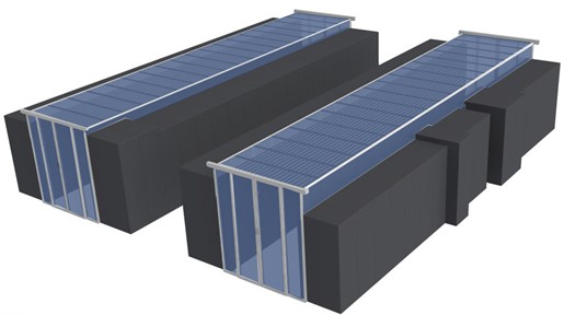
Figure 20 Figure 20. Aisle containment apparatus#
Aisle containment cannot be truly effective unless all pathways for airflow between the hot aisle and the cold aisle are blocked. For this reason, unoccupied RU spaces in the rack should be covered with blanking panels, and openings in the top, sides, or bottom of the rack, or subfloor, which are used for cable pass-throughs should be fitted with brush grommets.
System Operation and Maintenance#
Several system maintenance steps can help ensure optimal cooling performance. Among these are routine air filter changes, using the correct filter specifications, routine measurement of humidity levels within the space (with prescribed corrective actions when tolerances are not maintained), routine audits of the flow rates of perforated tiles in a plenum floor, and routine preventative maintenance cycles on all air handlers. It is also highly advisable to have accurate Computational Fluid Dynamics models of the data center space created so that planned changes can be modeled prior to implementation to assess their potential impact on critical systems.
Cooling Oversubscription#
When there is a delta between the capacity of a resource in the data center and the demand for that resource, the resource is said to be oversubscribed. Oversubscribed cooling can sometimes be mitigated by lowering the rack density thereby reducing the cooling demand per rack footprint, or by spacing the racks further apart to aggregate the cooling capacity of more than one rack footprint to each populated rack. Either solution consumes more data center space, and perhaps more importantly, requires longer cable runs to interconnect the racks. Careful attention should be given to cable length as it relates to these potential solutions.
Consider the following hypothetical deployment scenario with a single SU and its management racks being deployed in a high-density deployment pattern in an area of the data center that has constrained cooling capacity. Figure 21 depicts 358 kW of heat load in a deployment pattern that supplies only 260 kW of cooling capacity.
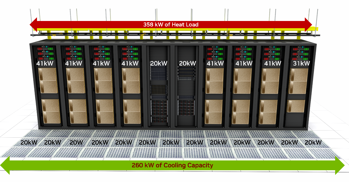
Figure 21 Figure 21. Cooling Oversubscription Scenario#
In this scenario, if the server racks were spaced apart by one rack footprint, additional cooling capacity can be leveraged.
Figure 22 depicts the same deployment pattern, spaced apart in this manner. Now, the 358 kW of demand is supplied by 460 kW of cooling capacity.
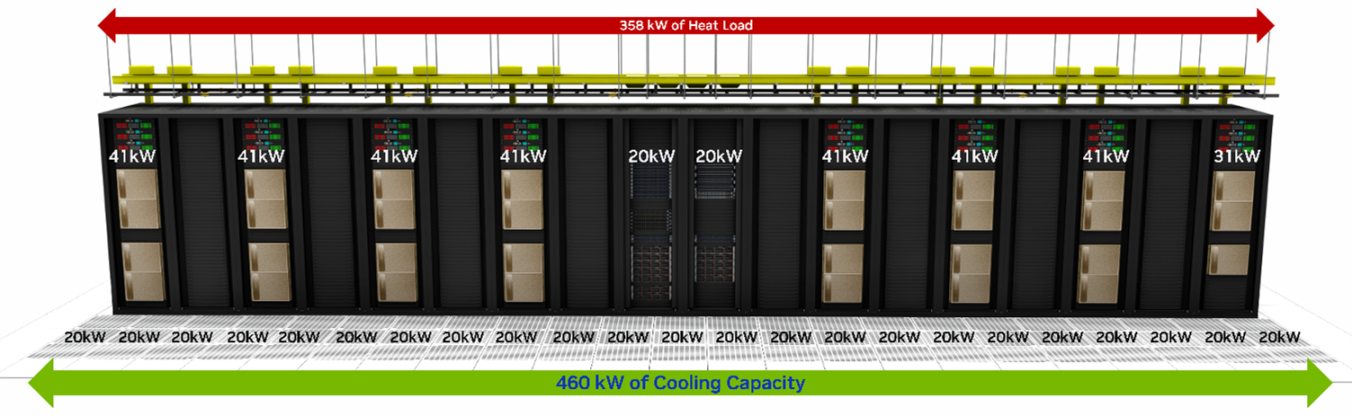
Figure 22 Figure 22. Resolved cooling oversubscription#
As previously noted, the cooling oversubscription could also have been resolved by reducing the rack density. This may have consumed even more additional space, depending on the actual cooling capacity per rack footprint, or it may have resulted in more stranded power capacity depending on the power provisioning options available for the racks. The objective is to resolve any oversubscription scenario using the method that consumes or wastes the fewest alternate resources (in this case, space and/or power) to arrive at the most optimal deployment pattern possible.
Caution
For Illustration purposes, the management racks in Figures 21 and 22 are both depicted as producing 20kW of heat load. In practice, each management rack’s power consumption and heat load is unique and can vary based on individual deployment requirements. The 20kW number is simply an average heat load used to demonstrate the concept in the illustration and should not be used as a substitute for precise power or cooling capacity planning in an actual deployment.