Planning a Data Center Deployment#
This documentation is part of NVIDIA DGX SuperPOD: Data Center Design Featuring NVIDIA DGX H100 Systems.
Use this documentation to learn about the following:
Coordination#
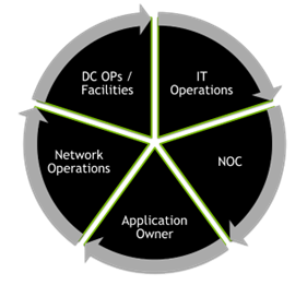
The planning of a DGX SuperPOD deployment requires coordination and alignment of multiple constituencies within an organization and may impact third-party vendors that provide critical services to those teams. Teams that can be impacted include the application owner, end-users, data center operations, facilities teams, security, various information technology and networking teams, and network operations center support teams. The various teams must have alignment to ensure a well planned and executed installation of a DGX SuperPOD.
During the planning and implementation, changes that occur in one technical domain can impact on another domain. For example, if there is a power constraint that limits rack density and causes the implementation to be distributed across a higher number of rack footprints, not only will that impact the data center facility’s floor layout plan, but it will likely also impact the network—necessitating a recalculation of cable lengths and possibly introducing latency-related performance impacts. Good alignment, coordination, and communication among the various domain experts at every phase of the design and implementation of a DGX SuperPOD deployment will create the best result.
The Economy of Data Center Resources#
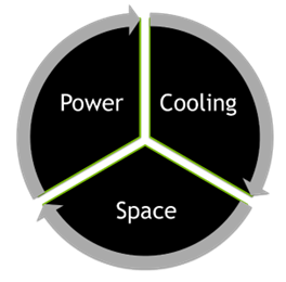
In every data center environment, there are finite resources. Just as in an economy, the constraints or limitations in the supply of these resources creates scarcity in the face of demand. This drives the need to optimize resource utilization to achieve overall efficiency and maximum return on the investments made in those data center facilities.
The three main resource constraints in an air-cooled data center environment are power, cooling, and space.
The interrelationship between these resources is such that scarcity of one resource could create increased demand for another resource. For example, limitations in cooling capacity could constrain rack power density, resulting in a need to occupy a larger number of racks to house a given number of servers. In this example, the resource constraint in cooling is “paid for” using floor space. This enables the deployment to take place, although it is not an optimized use of floor space in the data center.
DGX H100 Key Specifications#
The NVIDIA DGX SuperPOD with NVIDIA DGX H100 systems is an optimized system for multi-node DL and HPC. It typically consists of between 31 and 127 DGX H100 systems (Figure 1), with a total of 1,016 NVIDIA Hopper GPUs. It is built using the NVIDIA DGX SuperPOD Reference Architecture and is configured to be a scalable and balanced system providing maximum performance.
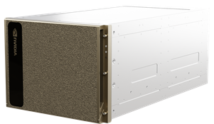
Figure 1 Figure 1. DGX H100 system#
Key specifications of the DGX H100 system are in Table 1.
Specification |
Value |
|---|---|
System power consumption |
10.2 kW max |
System weight |
287.6 lb (130.45 kg) |
System dimensions |
14 x 19.0 x 35.3 in (356 x 482.3 x 897.1 mm) |
Rack units |
8 |
Cooling |
Air |
Operating temperature |
5—30°C (41—86°F) |
Operating altitude |
|
Acoustic noise operating |
|
PSU redundancy |
|
Caution
Due to the weight and size, high power requirements, high heat rejection, and the sound power level of this equipment, operator safety is of major importance. Personal Protective Equipment (PPE) must be worn, and safety procedures must always be observed when working on or near DGX H100 systems.
Density of Compute Racks#
Every data center has its own unique constraints regarding power, cooling, and space resources. NVIDIA has developed DGX SuperPOD configurations to address the most common deployment patterns. However, should customization be necessary to address specific data center parameters in a particular deployment, NVIDIA can typically accommodate. It is important to work with NVIDIA and communicate any data center design constraints, so that a performance optimized deployment can be achieved. Altering the deployment pattern without such consultation can lead to serious performance, operational, support, or scalability challenges.
The building block of a DGX SuperPOD configuration is a scalable unit (SU). Each scalable unit consists of up to 32 DGX H100 systems plus associated InfiniBand leaf connectivity infrastructure. A DGX SuperPOD can contain up to 4 SU that are interconnected using a rail optimized InfiniBand leaf and spine fabric. A pair of NVIDIA Unified Fabric Manager (UFM) appliances displaces one DGX H100 system in the DGX SuperPOD deployment pattern, resulting in a maximum of 127 DGX H100 systems per full DGX SuperPOD.
DGX H100 systems are optimally deployed at a rack density of four systems per rack. However, rack densities can be customized to fit within the available power and cooling capacities at the data center. Naturally, reducing rack density increases the total number of required racks.
Some specifications are shown in Table 2.
Number of DGX Systems per Rack |
Number of DGX System Racks |
Total SU Server Rack Power Requirement |
Total Power Per Rack Footprint |
|---|---|---|---|
1 |
32 |
326.4 kW |
10.2 kW |
2 |
16 |
326.4 kW |
20.4 kW |
4 |
8 |
326.4 kW |
40.8 kW |
In addition to these racks, every SU also requires two management racks for the InfiniBand leaf and spine infrastructure, management servers, and storage infrastructure. The specific configurations of these racks can vary based on the NVIDIA DGX SuperPOD Reference Architecture. Use the values provided in Table 2 to assist in calculating the power requirements for these racks.
The design of the InfiniBand fabric within the DGX SuperPOD architecture presents constraints regarding cable path distance (the total distance of travel must not exceed 50m for any InfiniBand cable). Therefore, the deployment patterns are modeled with careful attention to cable length.
Safe System Delivery#
The following considerations are essential for the safe delivery of equipment to the data center location:
The facility should have a loading dock or permit a liftgate equipped delivery vehicle.
If there is no loading dock, a hydraulic lift or ramp must be provided to safely offload pallets.
There must be a secure receiving room or staging area separate from the data hall to store equipment before installation.
There must be clear access between the loading dock and the receiving room.
There must be adequate space in the receiving room to remove equipment components from pallets before transferring to the data hall. All shrink-wrap, cardboard, and packing material should remain in the receiving room.
Conveyances must be available to safely move equipment from the receiving room to the data hall.
NVIDIA components will be put on pallets for shipping by common carriers. Pallet information for the DGX H100 system is provided in Table 3.
Specification |
Value |
|---|---|
Units/Pallet |
1 |
Actual Product Weight |
287.6 lb (130.45 kg) |
Chargeable Product Weight |
376 lb (170.45 kg) |
Pallet Weight |
421 lb. (191 kg) |
Product Box Dimensions |
38.2 x 28 x 46.5 in (970 x 711 x 1,178 mm) |
Overpack Material (Crate/Corrugated Box) |
Corrugated box |
Depending upon the size of the DGX SuperPOD configuration, up to 127 DGX system pallets along with numerous network switches, management server appliances, and cables will be shipped. Procurement teams and suppliers should coordinate with onsite data center personnel to ensure that the material can be received and stored in a secure location before installation.
Power and Heat Dissipation#
Management racks contain network infrastructure, storage, and management servers for the DGX SuperPOD, in varying quantities based on the number of SUs being deployed. Each system component has an expected average power (EAP) and an expected peak power (EPP).
EAP, EPP, and heat dissipation values for key components of a full DGX SuperPOD are shown below.
| Servers | Switches | ||||||||
|---|---|---|---|---|---|---|---|---|---|
| Compute | Storage | Mgmt | Fabric | Compute | Storage | In-band Mgmt | OOB Mgmt | ||
| Model | DGX H100 | Varies1 | PowerEdge R7501 | NVIDIA UFM 3.1 | QM9700 | QM9700 | SN4600C | SN2201 | |
| Qty | 127 | Varies1 | 5 | 4 | 48 | 16 | 8 | 8 | |
| EAP (Watts) | Each | 10,2002 | 2,880 | 704 | 600 | 1,376 | 1,376 | 466 | 98 |
| Subtotal | 1,295,400 | 17,280 | 3,520 | 2,400 | 66,048 | 22,016 | 3,728 | 784 | |
| EPP (Watts) | Each | 10,200 | 3,600 | 880 | 750 | 1,720 | 1,720 | 820 | 135 |
| Subtotal | 1,295,400 | 21,600 | 4,400 | 3,000 | 82,560 | 27,520 | 6,560 | 1,080 | |
| Peak Heat Load (BTU/h) | Each | 34,804 | 12,284 | 3,003 | 2,559 | 5,869 | 5,869 | 2,798 | 461 |
| Subtotal | 4,420,088 | 73,702 | 15,013 | 10,236 | 281,706 | 93,902 | 22,384 | 3,685 | |
| Percent of System Total | 89.83% | 1.50% | 0.31% | 0.21% | 5.72% | 1.91% | 0.45% | 0.07% | |
See NVIDIA DGX SuperPOD Reference Architecture. Typical example depicted.
DGX H100 systems operate at or near peak utilization continuously when running AI workloads
In general, the design requires a minimum airflow of 157 ft 3/min (4.445 m3/min) per kilowatt. However, the actual requirements can vary based on the environmental conditions and altitude of each specific data center, as well as the Delta T of each component.
Environmental Thermal Guidelines#
Table 4 illustrates the general ASHRAE temperature and humidity standards for the cooling of IT and telecommunications equipment. To meet the cooling demands of DGX SuperPOD, data center facilities should satisfy the Recommended requirements, and at the very least must satisfy the Class A1 requirements up to the limits noted.
Range |
Class |
Dry-Bulb Temperature |
Humidity Range, Non-Condensing |
Maximum Dew Point |
|---|---|---|---|---|
Recommended |
All A |
64.4-80.6°F 18-27°C |
41.9°F to 60% RH and 59°F DP 5.5°C to 60% RH and 15°C DP |
59°F 15°C |
Allowable up to 30°C for DGX H100 Systems |
A1 |
59-89.6°F 15-32°C |
20-80% RH |
62.6°F 17°C |
Allowable per ASHRAE for various other classes of data center and telecom environments |
A2 |
50-95°F 10-35°C |
20-80% RH |
69.8°F 21°C |
A3 |
41-104°F 5-40°C |
10.4°F DP and 8-85% RH -12°C DP and 8-85% RH |
75.2°F 24°C |
|
A4 |
41-113°F 5-45°C |
10.4°F DP and 8-90% RH -12°C DP and 8-90% RH |
75.2°F 24 °C |
|
B |
41-95°F 5-35°C |
8-80% RH |
82.4°F 28°C |
|
C |
41-104°F 5-40°C |
8-80% RH |
82.4°F 28°C |
Source air contamination (such as smoke, dust, pollution, or other types of contamination) must be mitigated through filtration.
Table 5 describes the ISO 14644-1 maximum particle sizes for different classes of air cleanliness. In an Airside Economizer Mode, or any other environment where source air may be contaminated, the air must be filtered by a minimum MERV 13 (or EN779-2012 M6/F7, or ISO 16890 ePM1-50%) rated filter, and the rack area must meet the cleanliness level of ISO 14644-1 Class-8 standard with maximum particle counts not to exceed 3,520,000 @ 0.5 µm/m3 for no longer than 15 minutes.
Class |
Particle Size1 |
|||||
|---|---|---|---|---|---|---|
> 0.1 µm |
> 0.2 µm |
> 0.3 µm |
> 0.5 µm |
> 1 µm |
> 5 µm |
|
1 |
10 |
2 |
||||
2 |
100 |
24 |
10 |
4 |
||
3 |
1,000 |
237 |
102 |
35 |
8 |
|
4 |
10,000 |
2,370 |
1,020 |
352 |
83 |
|
5 |
100,000 |
23,700 |
10,200 |
3,520 |
832 |
29 |
6 |
1,000,000 |
237,000 |
102,000 |
35,200 |
8,320 |
293 |
7 |
352,000 |
83,200 |
2,930 |
|||
8 |
3,520,000 |
832,000 |
29,300 |
|||
9 |
35,200,000 |
8,320,000 |
293,000 |
|||
Uncertainties related to the measurement process require that data with no more than three significant figures be used in determining the classification level.
Table 6 provides a general comparison of filtration standards as a cross-reference.
ASHRAE Standard 52.2-2007 Minimum Efficiency Reporting Value (MERV)1 |
EN 779-2012 |
ISO 16890 |
|---|---|---|
MERV 1, 2, 3, 4 |
G1, G2 |
— |
MERV 5 |
G3 |
— |
MERV 6, 7, 8 |
G4 |
Coarse 90% |
MERV 8, 9, 10 |
M5 |
ePM10-60% |
MERV 9, 10, 11, 12, 13 |
M6 |
ePM2.5-50% |
MERV 13, 14 |
F7 |
ePM1-50% |
MERV 14, 15 |
F8 |
ePM1-75% |
MERV 16 |
F9, E10, E11, E12, H13, H14, U15, U16 |
— |
The testing and evaluation procedures for the ASHRAE 52.2, EN 779-2012, and ISO 16890 are significantly different, making direct comparisons of filter efficacy and efficiency difficult and potentially misleading. The values in this table are provided as a general reference but should not be considered scientifically precise.