Electrical Specifications#
This documentation is part of NVIDIA DGX SuperPOD: Data Center Design Featuring NVIDIA DGX H100 Systems.
Use this documentation to learn about the following:
Data Center Power Configuration#
The DGX SuperPOD is typically deployed with a rack density of four DGX H100 systems per rack, although deployments with lower rack densities are possible. Combining international norms on voltages and circuit protection yields common power provisioning patterns for data centers. A DGX H100 power supply system using components certified for 200-240 VAC can be deployed world-wide. Connectors, distribution boxes, fuses, circuit breakers, and wire gauges selected at compatible steps ease certification and installation. Rack power distribution units (rPDUs) typically derive 200-240 VAC single phase power by dividing a three-phase input power circuit into three individual single-phase circuits.
Table 7 identifies the most common supply/distribution voltages and currents that can support the defined SU deployment patterns.
Phase |
Distribution Voltage |
Line Voltage |
Amps |
Breaker Derating |
Circuit Capacity kW1 |
Maximum Supported DGX H100 Systems per Rack2,3 |
Peak Server Demand per Circuit kW2 |
Stranded Capacity at Peak Demand kW2 |
|---|---|---|---|---|---|---|---|---|
1Φ |
230 |
230 |
63 |
100% |
13.7 |
2 |
10.2 |
3.5 |
3Φ Delta |
208 |
208 |
60 |
80% |
32.8 |
4 |
20.4 |
12.4 |
3Φ Wye |
400 |
230 |
32 |
100% |
21 |
4 |
20.4 |
0.6 |
3Φ Wye |
415 |
240 |
32 |
100% |
21.8 |
4 |
20.4 |
1.4 |
3Φ Wye |
415 |
240 |
60 |
80% |
32.7 |
4 |
20.4 |
12.3 |
0.95 power factor.
Based on a three circuit N+1 power provisioning scheme where no circuit carries more than 50% of the load.
Rack densities greater than 4 DGX H100 Systems are not recommended, due to thermodynamic considerations
The preferred power for high-density deployment patterns is 415 VAC, 32A, three-phase, N+1. The design can be modified to support other supply voltage schemes, depending on the number of servers per rack. Power supplied to each rPDU must originate from separate data center floor-mounted or busway PDUs. All power feeds must be supported by facility-level UPS and generator back-up power to mitigate the risk of power loss.
Power Redundancy#
Generally, the data center should meet or exceed Uptime Institute Tier 3 design standards, or alternatively the TIA942-B Rated 3 or EN50600 Availability Class 3 design standards, including concurrent maintainability and no single point of failure.
In addition to those foundational standards, the DGX H100 system has additional requirements regarding power redundancy and resiliency. The system includes six internal power supply units. Four power supply units must be energized for the server to operate.
Caution
Four of the six power supplies must be energized for the system to operate. This is a critical data center design consideration.
A failure of a single system in a multi-node AI workload will cause the entire job to stop on all the systems. In environments where system availability is paramount, and work would not be recoverable (for example, from a checkpoint), a minimum of three power sources (rPDUs fed by discrete upstream power distribution paths), must be provisioned to each rack. Each of those sources will connect to two of the six system power supplies on each system, guaranteeing that a failure or maintenance event on any one of those sources will leave a minimum of four system power supplies energized.
Due to this requirement, the data center must minimally provide N+1 power, where N equals two power sources. Each power source must be sized to support 50% of the total peak load. This requirement applies to DGX H100 systems racks only. Management racks may be powered with traditional 2N redundancy using two power feeds.
The following illustrations and tables describe three power provisioning design concepts, each with their own advantages and disadvantages. Other power provisioning solutions are also possible, depending on the unique power system architecture of a given data center site. Consult with NVIDIA to determine if an alternate solution will meet the DGX SuperPOD availability requirements.
Traditional Redundant Power#
For a data center supplied with two utility feeds or two UPSs supplying power to the racks, Figure 4 and numref:traditional-redundant-power describe traditional power provisioning of each DGX system.
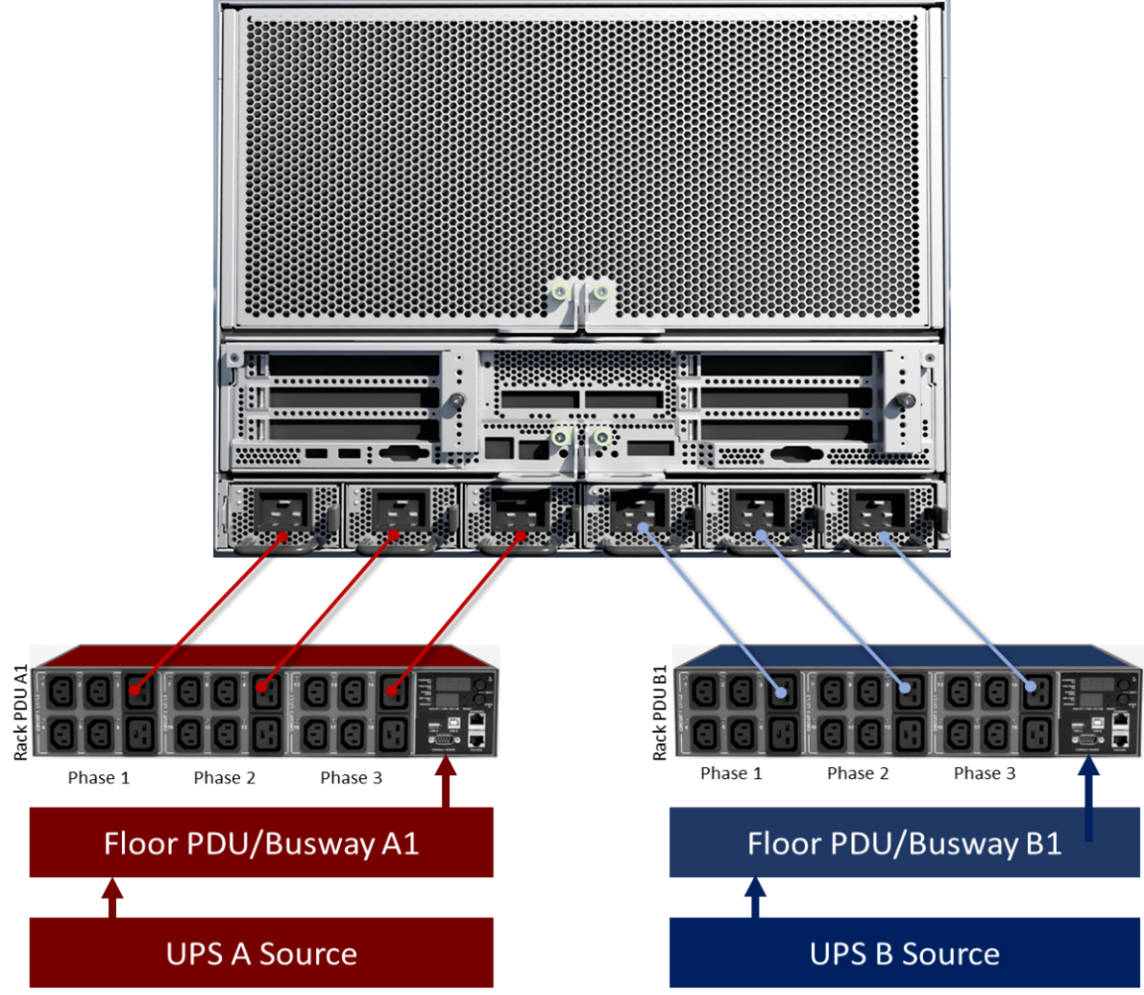
Figure 4 Figure 4. Traditional redundant power provisioning pattern#
Advantages |
Provides basic 2N power redundancy for typical I.T and network devices. Sufficient for management racks, but not for DGX H100 system racks. Compatible with nearly all data centers. |
|---|---|
Disadvantages |
During a failure of one power source, the number of energized PSUs on a DGX H100 system would fall below four, resulting in a shutdown of that system. Any active AI workloads running on that system at the time of failure will cease, resulting in a disruption to that job on all systems. |
Grade |
Not acceptable for DGX H100 systems |
N+1 Configuration#
Figure 5 and Table 9 illustrate a typical configuration for a data center with two UPSs supplying three power paths to the racks. Wherever possible, the load should be distributed so that one rack features two feeds from UPS B, and the next rack features two feeds from UPS A, in a repeating pattern. This minimizes dependency on any given UPS source and balances the load across them.
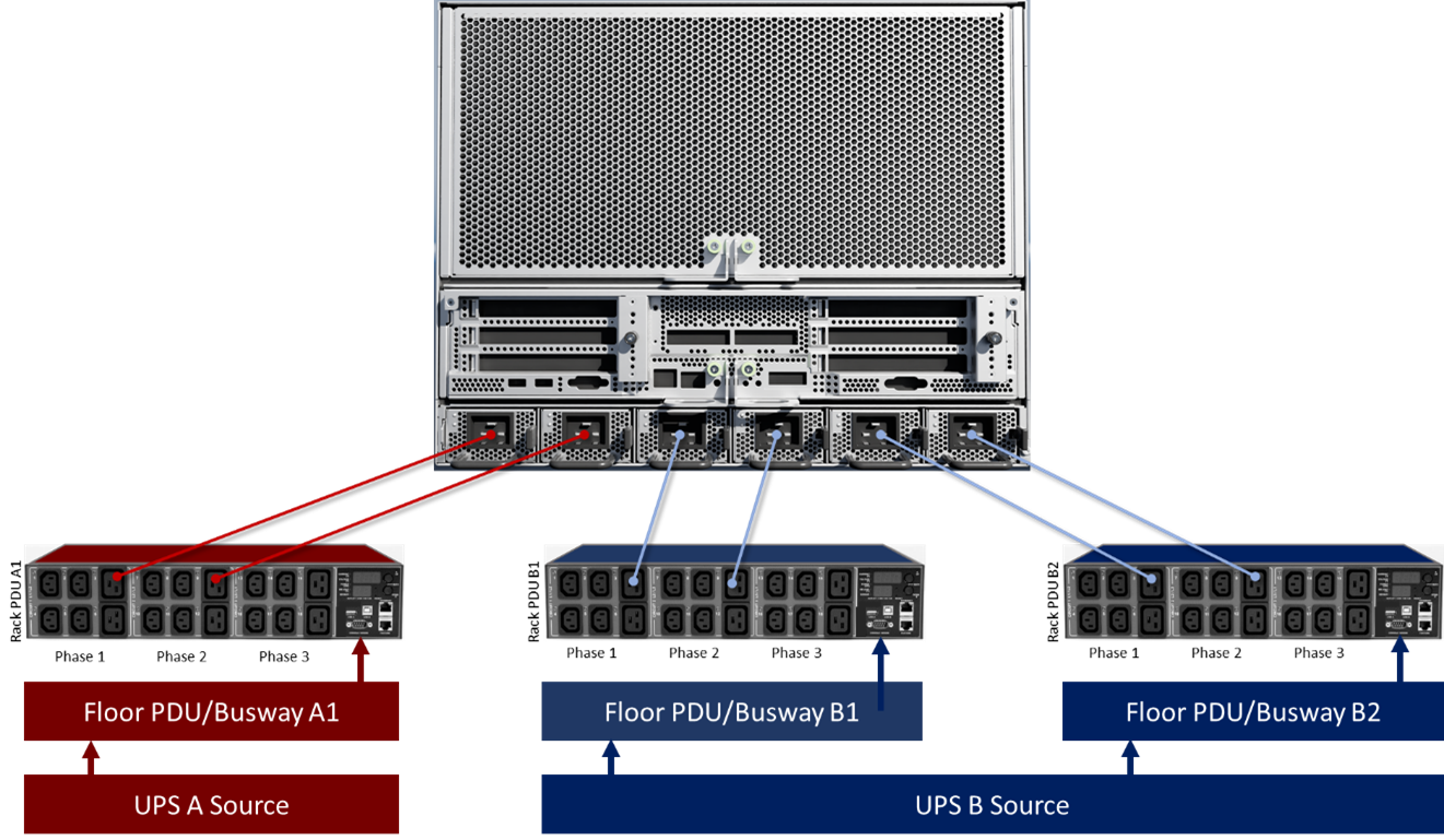
Figure 5 Figure 5. N+1 power provisioning pattern#
Advantages |
Provides basic power redundancy, and the ability to support AI workloads during a local power loss or maintenance event caused by a system PSU, a single rPDU, or a Floor PDU/RPP breaker. Compatible with most data centers. |
|---|---|
Disadvantages |
Adds complexity and cost. Two of the three rPDUs (powering a total of four system PSUs) are supplied by the same upstream UPS power source. Therefore, a failure or maintenance event affecting that upstream UPS would cause the system to power off. |
Grade |
Acceptable. Fault tolerant for most common failure modes, but some risks remain unmitigated |
Enhanced N+1 Configuration#
Figure 6 and Table 10 illustrate a power provisioning scheme using three discrete UPS systems, providing three discrete power distribution paths.
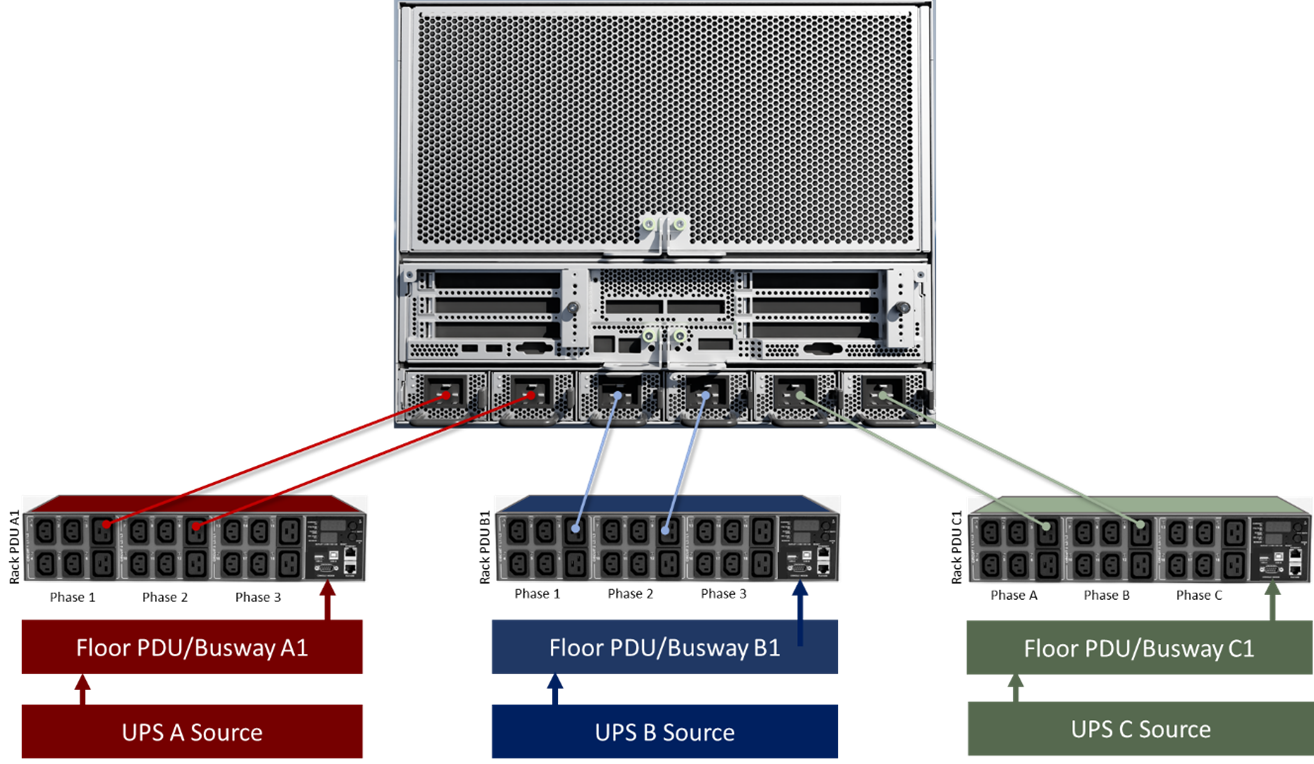
Figure 6 Figure 6. Enhanced N+1 power provisioning pattern#
Advantages |
Provides both fault tolerance and the ability to support AI workloads during a power loss or maintenance event that affects a single upstream power distribution path. Each rPDU is powered by a discrete upstream UPS/Power Distribution Path. |
|---|---|
Disadvantages |
Many data centers are not designed to provide power from three discrete upstream UPS/power distribution paths. |
Grade |
Acceptable. Optimal provisioning pattern for maximum performance and reliability. |
Planning and Deploying Power Connections#
Follow these best practice guidelines when connecting AC power to the racks and systems:
Validate AC power redundancy at each server rack. An outage could occur if these requirements are not met.
Complete power provisioning within the data center before connecting power to the rPDUs and system deployment.
Have an electrician or qualified facilities representative verify that the kVA supplied is within specification at each of the floor-mounted PDUs and individual circuits that feed the racks.
Label all the power connections to indicate the source of power (PDU #) and the specific circuit breaker numbers used within each PDU.
Color code the power cables (and associated rPDUs) to help ensure that redundancy is maintained.
Clearly label the equipment served by each circuit breaker within the PDU.
Earth/bond the data center racks to the telecommunications ground that in turn will be connected to the facility ground system.
Have an electrician or qualified facilities representative verify that there are three or more power connections fed from separate redundant PDUs before turning on the system.
Have an electrician perform an AC verification test by turning off the individual circuit breakers feeding each rack power strip to verify that power redundancy has been achieved in each rack.
Rack Power Distribution Unit (rPDU) Selection#
This section describes different options for providing redundant power. Each of the three required power input paths must support one half of the expected peak power of the rack. Keep in mind however, that for the typical N+1 provisioning pattern, two of the three power paths will eventually converge at some upstream junction (Such as a Room PDU or UPS), so that junction point must still be sized to manage each downstream rack’s full peak load.
rPDU features should include remote power monitoring Rest API capability for automation, and rack temperature/humidity monitoring.
For optimal integration into the DGX SuperPOD architecture, NVIDIA recommends using Raritan, Vertiv/Geist, or ServerTech rPDUs whenever possible.
Due to cable management and cabinet depth limitations, in addition to the potential quantity of rPDUs to be deployed, horizontal rPDUs may be required. Vertical (0U) rPDUs are an option only in racks of sufficient width and depth where they would not block access to any portion of the back of the system chassis, and they shall be mounted at the rearmost mounting points at the back of the rack. A maximum of two vertical PDUs are possible, therefore the remaining rPDU must be horizontal. NVIDIA can be consulted to provide rPDU recommendations based on the target data center’s power provisioning specifications. NVIDIA can also provide recommendations for the power outlet mapping that is specific to the selected rPDUs, to ensure proper electrical phase/load balancing across multiple PDUs.
Phase Balancing#
The power draw across the phases of a three-phase circuit should be as balanced as possible. In simple terms, a three-phase circuit is said to be unbalanced when the load on one of its phases is drawing more current than the average drawn by all three. This has several negative implications, including possible thermal derating of the conductors, deviation of proper electrical phase angle, possible damage to upstream transformers, unanticipated breaker trips during failover events, and most noticeably, stranding of the power capacity of the other phases should one phase reach 100% utilization before the others.
While it is typically not possible to balance the utilization on all three phases perfectly, minimizing the delta between phases is highly advantageous. Figure 7 shows that Phase A has reached 100% utilization, while Phases B and C have 25% and 50% respectively, of their capacity still available. That unused capacity is effectively stranded due to the unbalanced utilization pattern.
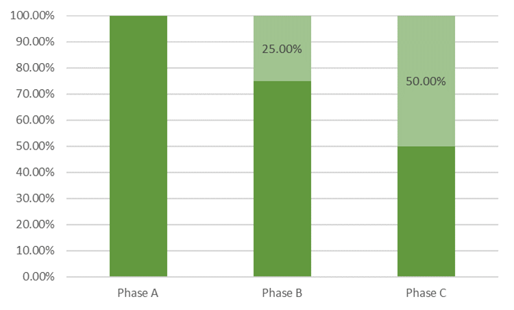
Figure 7 Figure 7. Unbalanced phase utilization#
For this reason, each PSU of each system should be connected to a different “leg” (or phase) on the rPDUs. The onboard metering function of the rPDU provides an indication of power draw per phase or circuit, to assist in evaluating phase balancing. In a system with potentially complex power provisioning schemes, such as the DGX SuperPOD, phase balancing is especially important.
It takes two racks of systems to balance the phases while maintaining the availability and performance characteristics of the N+1 design. Rack 1 is described in Figure 8 and Table 11, with rack 2 being described in Figure 9 and numref:logical-phase-r2. The PSUs on the systems are grouped in pairs, with each pair feeding from defined phases on specific rPDUs. Note that for each PDU that is sharing a common upstream UPS source, the feeder circuit for it is coming from a different floor PDU or busway, to maximize upstream diversity. For clarity of illustration, only two systems are depicted for each rack. However, the same patterns are employed with higher rack densities.
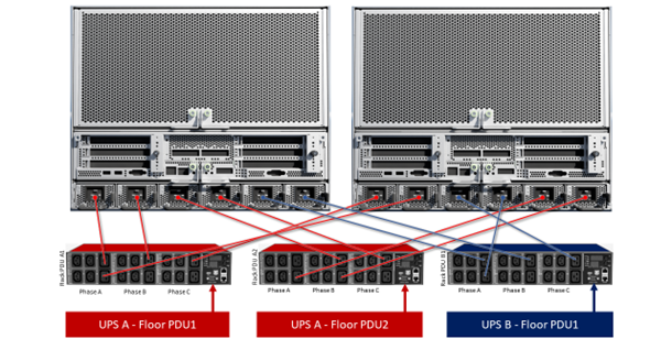
Figure 8 Figure 8. N+1 Phase balancing scheme—rack 1#
UPS/Gens |
Floor PDU |
rPDU |
PSU Phase Assignments |
|||||||||||
|---|---|---|---|---|---|---|---|---|---|---|---|---|---|---|
DGX H100 #1 |
DGX H100 #2 |
|||||||||||||
PSU1 |
PSU2 |
PSU3 |
PSU4 |
PSU5 |
PSU6 |
PSU1 |
PSU2 |
PSU3 |
PSU4 |
PSU5 |
PSU6 |
|||
Power Path A |
PDU1 |
rPDU A1 |
A |
B |
C |
A |
||||||||
Power Path A |
PDU2 |
rPDU A2 |
B |
C |
A |
B |
||||||||
Power Path B |
PDU1 |
rPDU B1 |
A |
B |
C |
A |
||||||||
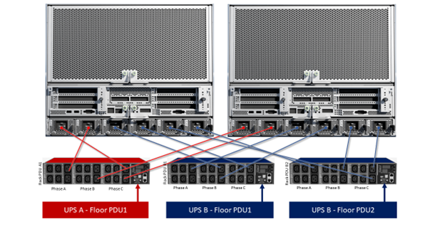
Figure 9 Figure 9. N+1 Phase balancing scheme—rack 2#
UPS/Gens |
Floor PDU |
rPDU |
PSU Phase Assignments |
|||||||||||
|---|---|---|---|---|---|---|---|---|---|---|---|---|---|---|
DGX H100 #1 |
DGX H100 #2 |
|||||||||||||
PSU1 |
PSU2 |
PSU3 |
PSU4 |
PSU5 |
PSU6 |
PSU1 |
PSU2 |
PSU3 |
PSU4 |
PSU5 |
PSU6 |
|||
Power Path A |
PDU1 |
rPDU A1 |
C |
A |
B |
C |
||||||||
Power Path B |
PDU1 |
rPDU B1 |
B |
C |
A |
B |
||||||||
Power Path B |
PDU2 |
rPDU B2 |
C |
A |
B |
C |
||||||||
For Enhanced N+1 power, the phase balancing scheme is slightly less complex. As with N+1, it takes two racks (Figure 10 and Table 13 for rack 1, Figure 10 and numref:logical-phase-r2-e for rack 2) to complete the phase balancing pattern.
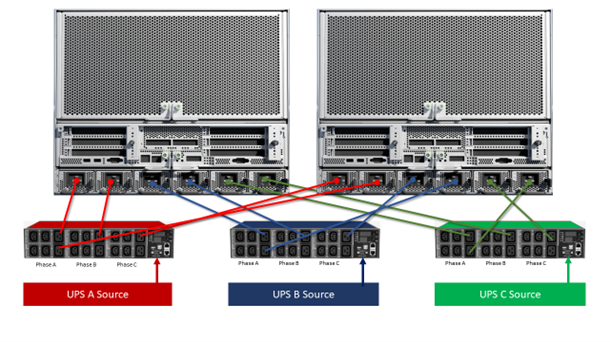
Figure 10 Figure 10. Enhanced N+1 Phase balancing scheme—rack 1#
UPS/Gens |
Floor PDU |
rPDU |
PSU Phase Assignments |
|||||||||||
|---|---|---|---|---|---|---|---|---|---|---|---|---|---|---|
DGX H100 #1 |
DGX H100 #2 |
|||||||||||||
PSU1 |
PSU2 |
PSU3 |
PSU4 |
PSU5 |
PSU6 |
PSU1 |
PSU2 |
PSU3 |
PSU4 |
PSU5 |
PSU6 |
|||
Power Path A |
PDU1 |
rPDU A1 |
A |
B |
C |
A |
||||||||
Power Path B |
PDU1 |
rPDU B1 |
A |
B |
C |
A |
||||||||
Power Path B |
PDU2 |
rPDU B2 |
A |
B |
C |
A |
||||||||
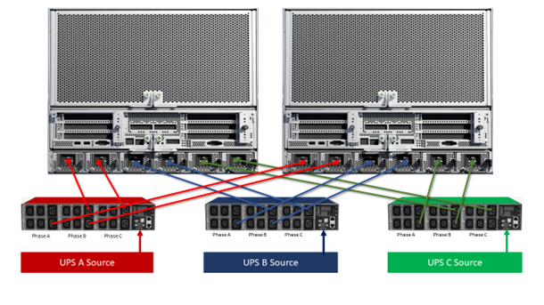
Figure 11 Figure 11. Enhanced N+1 Phase balancing scheme—rack 2#
UPS/Gens |
Floor PDU |
rPDU |
PSU Phase Assignments |
|||||||||||
|---|---|---|---|---|---|---|---|---|---|---|---|---|---|---|
DGX H100 #1 |
DGX H100 #2 |
|||||||||||||
PSU1 |
PSU2 |
PSU3 |
PSU4 |
PSU5 |
PSU6 |
PSU1 |
PSU2 |
PSU3 |
PSU4 |
PSU5 |
PSU6 |
|||
Power Path A |
PDU1 |
rPDU A1 |
B |
C |
A |
B |
||||||||
Power Path B |
PDU1 |
rPDU B1 |
B |
C |
A |
B |
||||||||
Power Path B |
PDU2 |
rPDU B2 |
B |
C |
A |
B |
||||||||