White Space Infrastructure#
This documentation is part of NVIDIA DGX SuperPOD: Data Center Design Featuring NVIDIA DGX H100 Systems.
Use this documentation to learn about the following:
Space Planning#
When deciding where to place an SU, many important factors including power capacity, cooling capacity, cable routing and management, and adjacent equipment requirements are usually considered. While these factors have a significant impact on location selection, thought should also be given to scalability. As the DGX SuperPOD expands from one scalable unit to two or more, there must be adjacent space available for that expansion. Performance-based cable length limitations prohibit distributing the racks or scalable units too far from one another. A well-planned deployment will consider future expansion and reserve sufficient floor space for the future state of the system, not just the initial state.
Rack Standards and Requirements#
Racks must conform to EIA-310 standards for enclosed racks with 19” EIA mounting. Cabinets must be at least 24” x 48” (600 mm x 1,200 mm) in size, and at least 48U tall. For proper cable management, rPDU placement, airflow management, and service clearance to the rear of the systems, NVIDIA recommends 32” x 48” (800 mm x 1,200 mm) racks. Racks must not have chimneys. Side walls must be installed in all racks.
For each rack, two temperature sensors will be connected to Ethernet ports in the PDU closest to the front of the rack. The sensors must be mounted at the front side of the rack, at the 4U position and at the 42U position. When facing the front of the rack, the sensors will be on the right side. Telcordia GR-63-CORE may also be followed for thermal rack measurements. Cable management devices are prescribed and must be used. For network switches, Air Intake ducts may be prescribed.
IT cabinets come in a variety of sizes and are often designed for specific purposes. Each cabinet OEM follows specific minimum EIA-310 standards to ensure that industry standard devices fit properly. But OEMs will enhance the EIA-310 standard with their own unique designs and features that allow them to stand out in the marketplace. These features may include:
Air management
Cable management
Modular sub-components
Removable components
Proprietary accessories
Supplemental security devices
Custom manufacturing, colors, company logos, and so on
Options When Ordering Cabinets#
Cabinet Doors
Unless mandated by facility operations or security policy, front and rear doors are not recommended. Eliminating the front and rear doors helps improve airflow and reduces cost.
Side panels
Side panels should be added and installed to maximize airflow management.
Grounding and Bonding Kit
This kit is often an optional item and may not come with the cabinet. Proper grounding and bonding are essential.
Blanking Panels
It is necessary to install blanking panels in each unused RU position to prevent exhaust air recirculation.
Cabinet Top Options and Accessories
Many cabinet manufacturers offer a range of cabinet top options and accessories to facilitate cooling management and cable routing management.
Whether it is a standard feature or an optional feature, cabinets must have sufficient cable ingress ports to support the volume of cabling traversing into the rack, and all such ports shall be protected with brush grommets or similar devices to control airflow. See Cabling Data Centers for more information.
Cabinet Mounting#
For the safety of staff members and equipment, all cabinets shall be fastened to the floor surface in accordance with manufacturer recommendations. This may involve bolting the cabinet through flanges or mount points designed for that purpose.
Seismic Considerations#
Wherever mandated by local authorities having jurisdiction (AHJs), cabinets mounted on raised floor surfaces may require seismic bracing to be installed in the subfloor space. Seismic bracing should be designed and installed by qualified licensed structural engineers specializing in seismic engineering.
Cabinet Selection vs. Cable Lengths#
The cabinet height and width combined with the overhead cable tray specification and layout will affect cable lengths. Cable length in InfiniBand networks is a critical performance factor. Point to point cable runs should be limited to a maximum of 165 ft (50m). Wherever possible, cable length should be a primary design criterion when selecting cabinet dimensions and designing overhead cable routing apparatus.
When selecting specifying rack width (Figure 12), attention should be given to the impact on cable lengths and row width.
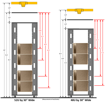
Figure 12 Figure 12. Dimensions for various cabinet options#
While wider racks are beneficial, it may be necessary to reduce the number of racks per row, or distribute the racks across two rows, so that maximum row width and optimum cable lengths can be maintained (Figure 13).
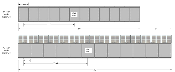
Figure 13 Figure 13. Row width based on rack width#
Server Mounting Requirements#
All DGX SuperPOD equipment is designed to be mounted in traditional IT server cabinets that conform to the EIA-310-D standard (Figure 14), which among other factors specifies the following:
Vertical Hole Spacing
Vertical hole spacing is defined as a repeating pattern of holes within 1 RU of 1.75″. The hole spacing alternates at: 1/2″ – 5/8″ – 5/8 and repeats. The start and stop of the “U” space is in the middle of the 1/2″ spaced holes.
Horizontal Spacing
The horizontal spacing of the vertical rows of holes is specified at 18 5/16″ (18.312) (465.1 mm).
Many manufacturers use equipment mounting slots instead of holes to allow for variations in this dimension.
Rack Opening
The space in the rack where the equipment is placed is specified as a minimum of 17.72″ (450 mm) wide.
Front Panel Width
The total width of the front face of the equipment (with its rack mounting brackets) is 19” (482.6 mm)
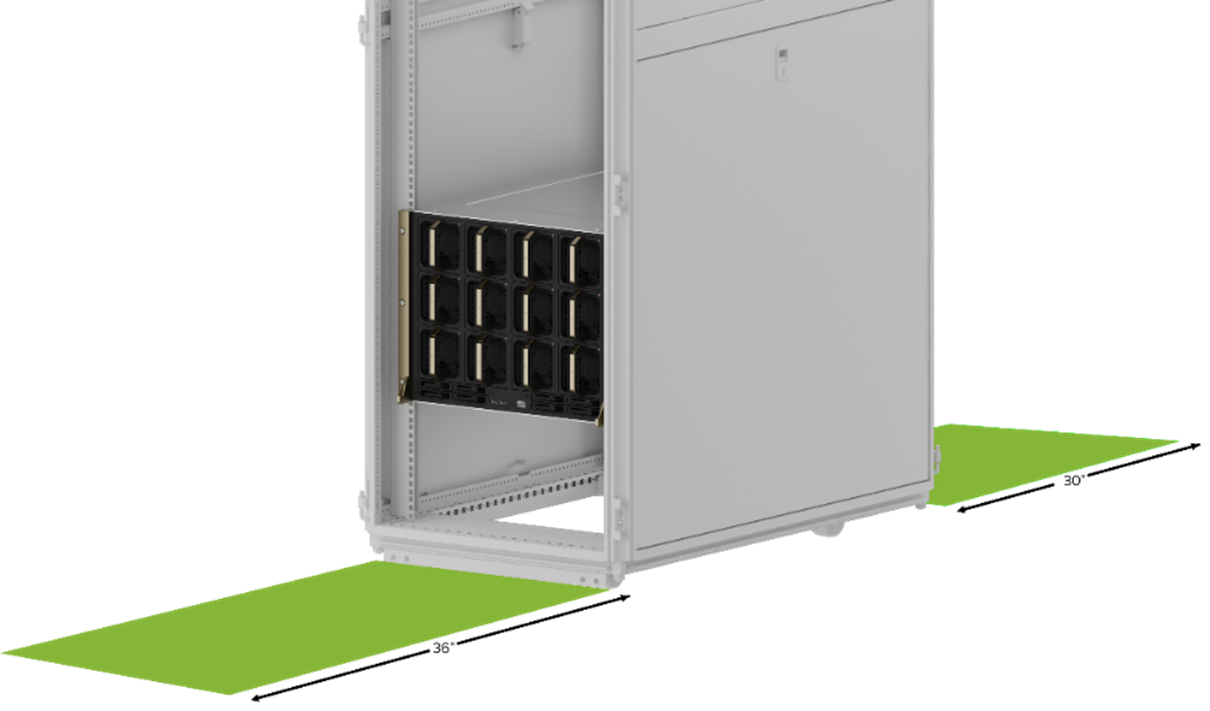
Figure 14 Figure 14. DGX H100 system mounted in EIA-310-D compliant server cabinet#
Racking Servers#
Another area requiring design attention is how and where the equipment will be mounted in the cabinet. This first involves setting the proper distance for the rack rails. This will set the horizontal orientation within the cabinet.
Some of the DGX SuperPOD devices are installed using a rail kit. A rail kit is a bracket specifically designed to support the full weight of the device in the rack, by spanning from the front rack rail to the rear rack rail. Rail kits are either a stationary shelf type bracket, or a bracket that allows the device to be pulled out of the rack enclosure on retractable struts. These rail kits have an extension range of 28–32 inches. Wherever provided, rail kits must be used in accordance with manufacturer recommendations.
Rail kit components for the DGX H100 system are shown in Figure 15.
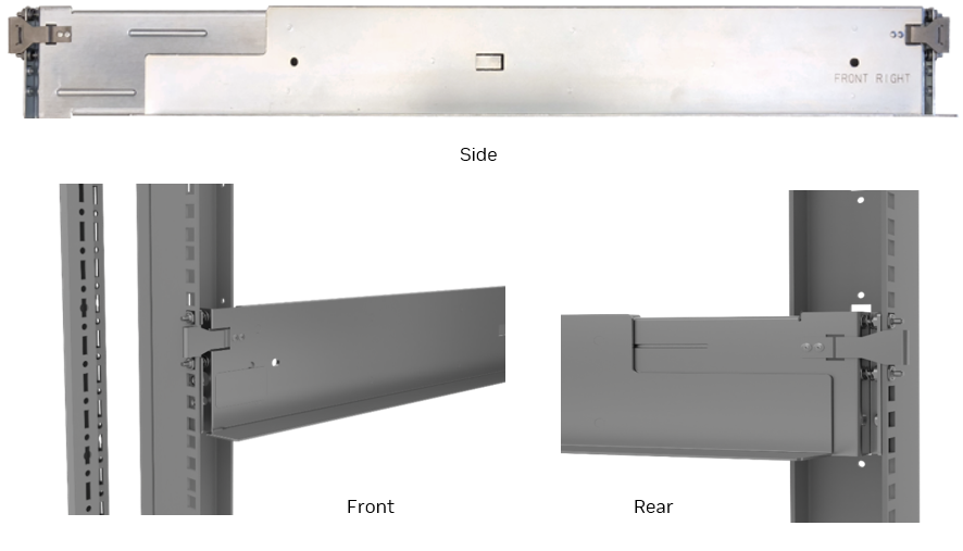
Figure 15 Figure 15. DGX H100 rail kit#
Due to their size and weight, servers should be mounted nearest the bottom of the rack, starting with the lowest position accessible by the server lift (usually rack unit position 3). It is optional, but not necessary, to have 1 RU between each server.
A typical high-density rack profile will have two servers grouped at the bottom of the rack, a 3 RU gap in the middle to aid in rack airflow management, and then two servers grouped above that (Figure 16). Horizontal rPDUs are typically placed near the top of the rack.
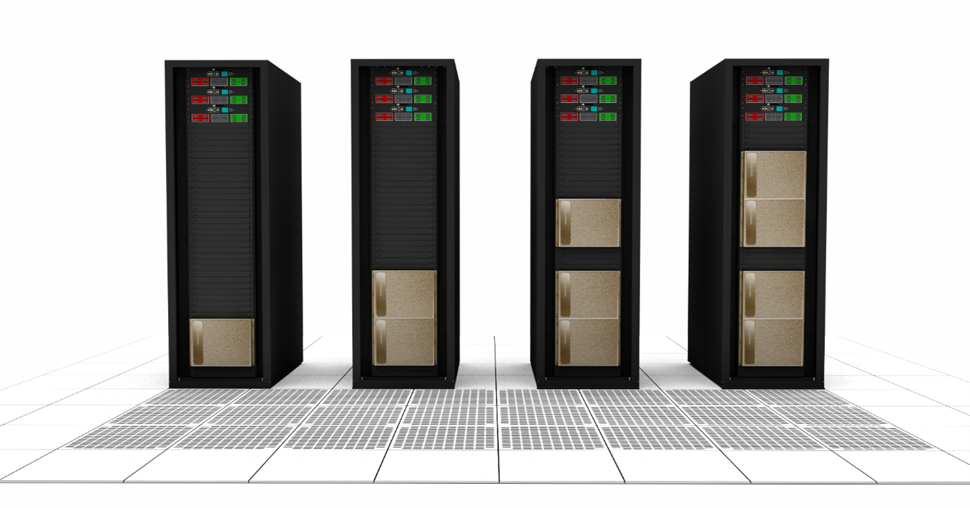
Figure 16 Figure 16. Server deployment positions for various rack densities#
Air Flow Management#
Some IT devices have the option of selecting the airflow direction through the device chassis. The determining factor for this choice is the expected hot aisle temperature. Servers and DGX H100 systems will always be oriented with front to rear airflow. However, network switches and appliances are typically configurable to align their airflow direction with front or rear rack placement. Typically network switches are mounted in the rear of the rack, with the network connectors facing the hot aisle. In this orientation, airflow enters through the back of the device chassis (the Power or “P” side) and is exhausted through the front of the device chassis (the network Connector or “C” side). This type of airflow orientation is referred to as “Power to Connector,” or “P2C”. This is the default mounting configuration and airflow orientation for data center network equipment, and the standard configuration for cable pathways into and out of server/network cabinets.
If the hot aisle will reach temperatures greater than 60°C (140°F), cabling (including power cabling) must either be moved to the cold aisle or derated. This means that the network switches will likely be mounted in the front of the rack with the network ports facing the cold aisle. In this orientation, air is ingested on the front “network connector” or “C” side of the chassis and exhausted from the rear “Power” or “P” side of the chassis. This airflow orientation is referred to as “Connector to Power,” or “C2P”.
Examples of P2C and C2P are shown in Table 15.
Direction |
Description |
Designation |
|---|---|---|
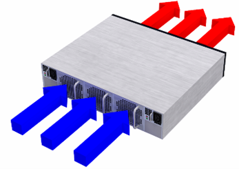
|
Power side inlet to Connector side outlet |
P2C |
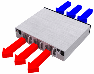
|
Connector side inlet to Power side outlet |
C2P |
The hot aisle temperature is directly correlated to the supply air temperature in the cold aisle, and the Delta T or expected heat rise of the equipment itself (usually 25-30°F). For example, with a supply air temperature of 70°F, and an expected Delta T of 30°F, the expected hot aisle temperature would be 100°F. Hot aisle temperatures exceeding 60°C/140°F are not typical.
If a C2P orientation is necessary, this choice must be made during BoM selection, because in many cases air flow is determined by the power supply fans and is not field modifiable.
Static Weight and Point Load#
A typical IT Cabinet has an average unloaded weight of 350 Pounds (158 Kg). An individual DGX H100 system weighs 287.6 Pounds (130.45 Kg). In addition to the servers and the cabinets themselves, peripheral devices such as rPDUs, blanking panels, cable management apparatus, environmental sensors, and cabling add additional weight. It is necessary to ensure that all flooring structures (including subfloor structures and slabs wherever applicable) are engineered to support the combined weight of the equipment racks they must support. It is also important to ensure that all ingress and egress pathways between the loading dock and the server room floor are engineered to support the combined weight of the equipment plus any conveyances used to move the equipment to the rack location. Table 16 lists the estimated (rounded) weight of different rack profiles. These are only general estimates. The exact weight of a specific loaded rack would depend on the unloaded weight of the actual rack model that was selected, as well as any extraneous peripheral components and cabling.
Number of DGX Systems per Rack |
Total Rack Weight (Pounds) |
Point Load (Pounds) |
Total Rack Weight (Kilograms) |
Point Load (Kilograms) |
|---|---|---|---|---|
1 |
650 |
217 |
295 |
98 |
2 |
925 |
308 |
420 |
38 |
4 |
1500 |
500 |
680 |
226 |
Server Lifts#
Due to the heavy weight of the DGX H100 system, it is necessary to use a server lift (Figure 17)to install and remove the devices from the racks, and to transport them to the rack location.
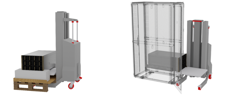
Figure 17 Figure 17. Server lifts#
Proper server lifts are designed specifically for use in data center environments to lift heavy but sensitive devices such as servers and network switch chassis into server cabinets. They include a platform to hold and lift the device, not forks that are like a forklift. General purpose materials lifts, including any lift that uses forks in place of a platform, are not suitable for use as server lifts—even if they are advertised for such uses. Use the server lift in compliance with all safety precautions and protocols as specified by the manufacturer. Ensure that the server lift is rated for a minimum of 350 pounds of weight. Ensure proper clearance below any overhead obstructions before lifting the device.
Security, Noise, and Fire Prevention#
In addition to the physical compute and network infrastructure, certain other site infrastructure and safety factors should also be considered when implementing a DGX SuperPOD. This section provides an overview of the top external considerations.
Physical Security#
The DGX SuperPOD, including servers and network infrastructure, should be protected against unauthorized physical access. Access controls to the data center are required to prevent system tampering, theft of intellectual property, data copying or unauthorized removal of data. Data center site security measures should minimally be certified SOC compliant, in addition to any other authorities having jurisdiction. This includes auditable door access controls and cameras that can identify a person entering the space and record that person’s actions within the space. Depending on the security policies and requirements governing the data and applications, DGX SuperPOD racks should be isolated from other unrelated IT racks using partitions or cages with access limited only to persons authorized to service the NVIDIA racks.
Noise#
NVIDIA DGX H100 systems can generate noise levels greater than 98 dB at 1m distance. Noise reduction measures and hearing protection are the responsibility of the data center operator and should be provided in accordance with the requirements of local authorities and industry regulations. See Sound Mitigation for further detail regarding noise risks and mitigations.
Fire Protection#
Fire detection and fire prevention systems/equipment are required in the data center. Regulations vary from one jurisdiction to another, resulting in the use of different fire detection and suppression schemes from one data center to another. A fire detection and suppression system is the responsibility of the data center operator and should be installed in accordance with the requirements of the customer’s insurance underwriter, local fire marshal, and local building inspector for the correct level of coverage and protection.