Networking#
This documentation is part of NVIDIA DGX SuperPOD: Data Center Design Featuring NVIDIA DGX H100 Systems.
A detailed examination of the network design and architecture is beyond the scope of this document. See the NVIDIA DGX SuperPOD Reference Architecture for an in-depth review of the network architecture, connectivity, and equipment. In the following sections, network infrastructure will be discussed only to the extent that it impacts data center design considerations.
Similarly, a detailed examination of data center cabling and cable management technology is also beyond the scope of this document. See Cabling Data Centers for more information.
Cable Weight#
Due to the volume of cables traversing the various cable pathways, it is important to ensure that all cable pathways have sufficient size and weight bearing capacity to facilitate the load. Generally, in the planning phase, the weights and sizes shown in Table 17 can be used to calculate load-bearing requirements for cable pathway apparatus such as cable trays, ladder racks, and strain reliefs, however, these are only a general guide. Use the actual specifications of the cables being installed once they have been determined.
Cable Type |
Average Single Cable Diameter |
Average Single Cable Weight |
|---|---|---|
Copper |
9.43 mm ± 0.4 mm |
|
AOC Fiber Optic |
3.0 mm ± 0.4 mm |
|
There is a large concentration of cables in the central management racks as well as in the supporting cable pathways overhead. Pre-planning for the cabling infrastructure is a critical part of the design process. Areas of analysis include:
Top of rack cable penetration access.
Cable tray types.
Cable tray width and depth.
Cable tray fill ratios.
Structural load/weight planning.
Cable management devices.
All cable management and pathway apparatus should be selected, installed, and maintained in accordance with applicable industry standards including ANSI/TIA, BICSI, and NEMA. Further, it should be installed in compliance with all locally applicable fire safety and electrical codes, such as National Electric Code (NEC) in the United States and Mexico, The Canadian Electric Code in Canada, The International Electrotechnical Commission (IEC) in Europe, The British Standard (BS) 7671 in the United Kingdom, and NF C 15–100 in France.
Compute fabric component and cable counts are shown in Table 18.
SU Count |
Cluster Size # Nodes |
Cluster Size # GPUs |
Leaf Switch Count |
Spine Switch Count |
Compute + UFM Node Cable Count |
Spine-Leaf Cable Count |
|---|---|---|---|---|---|---|
1 |
31a |
248 |
8 |
4 |
252 |
256 |
2 |
63 |
504 |
16 |
8 |
508 |
512 |
3 |
95 |
760 |
24 |
16 |
764 |
768 |
4 |
127 |
1016 |
32 |
16 |
1020 |
1024 |
a This is a 32 node per SU design; however a DGX H100 system must be removed to accommodate for UFM connectivity.
Front and rear views of a typical overhead cable management system of SU are shown in Figure 18 and Figure 19.
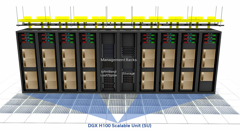
Figure 18 Figure 18. Typical overhead cable management of a SU—front#
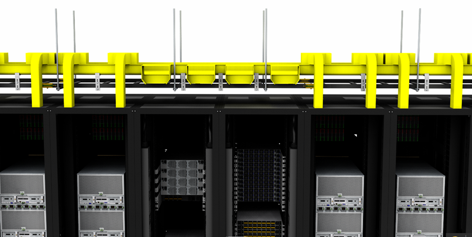
Figure 19 Figure 19. Typical overhead cable management detail—rear#
When selecting an overhead cable tray design, use the following formulas to calculate how many cables it will support:
A = Inside tray area (in square inches)
D = Cable diameter (inches)
F = Fill ratio (percent)
N = Number of cables
N = (F/100) * (A / [(D/2)2 * π])
This formula can be used to determine that a tray with a cross sectional area of 11.5 in2 (7,419 mm2) is the minimum size that will support the volume of cables in an SU, if the cables have an average diameter of 3 mm (such as an AOC cable) and a maximum tray fill ratio of 50% (it is not advisable to fill cable trays higher than 50%).
Care should be taken to ensure that any cable tray apparatus is structurally sound and designed for the weight of the cables that it supports. Typically, straight sections of cable tray are supported at 5 ft intervals, while curved sections may require additional supports. Any span greater than 5 ft in length should be evaluated to determine if additional supports are required. Supports should be placed within 1 ft of any splice or joint in the cable tray structure, or tray height transition. The support structures and the anchors that hold them should each be evaluated separately to ensure they will hold the combined weight of the cables, the tray apparatus, and supporting structures.
As a reference, for a single SU the structural load of the fiber cabling is 508 cables * 0.009 Kg per cable per linear meter, or 4.57 Kg (10 lbs) per linear meter. Again, the calculations illustrated here are general guidelines, and calculations based on the size and weight specifications of the specific quantities of the actual cables to be used should be performed.