DGX-2 KVM Performance Tuning
NVIDIA DGX-2 virtualization supports guest GPU VMs as described in the KVM chapter of the NVIDIA DGX-2 System User Guide. The guest VMs are statically resourced with the default number of resources such as vCPUs, GPUs, and memory. The default values take into consideration PCIe topology, CPU affinity, and NVLink topology to provide optimal performance.
These default settings can be overridden to provide additional performance optimizations. This chapter discusses these performance optimizations.
Background
Guest GPU VMs run as simple user-space Linux processes in the KVM Host while vCPUs are POSIX threads running in the Host. The Linux kernel running on the KVM Host uses a built-in scheduler to handle these processes and threads. The default settings provide generic functionality, but you may need to apply some level of performance tuning to achieve better performance. Since performance settings aren’t generic enough to accommodate every application’s needs, you should treat performance tuning as an iterative process - change a setting, run tests, then evaluate results, repeating the process until you achieve optimal performance for the particular application or set of applications. Use bare-metal values as a baseline of what can be achieved, then compare guest VM results to that of the bare-metal as you work towards improving the results.
Performance Tuning Using the Paravirtualized Drivers
The diagram below shows the I/O flow between the hypervisor and guests.
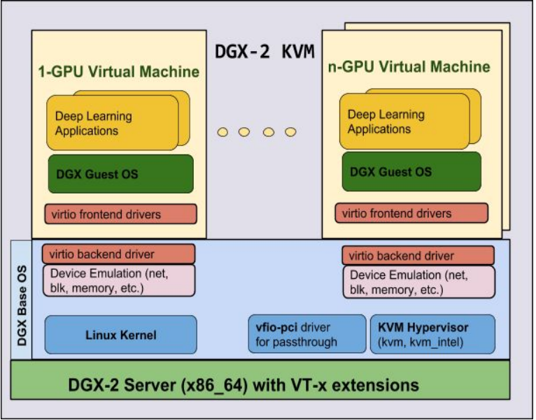
The DGX-2 KVM uses the following paravirtualized drivers (virtio) to help improve the DGX-2 KVM performance.
- virtio-net: The virtio-net driver supports virtual network devices.
- virtio-blk: The virtio-blk driver supportes virtual block devices (OS drive, Data drive).
- virtio-balloon: The virtio memory balloon driver manages guest memory.
- virtio-console: The virtio-console drivers manage data flow between the guest and KVM host
You can use change the default settings of these drivers to improve performance.
This chapter describes the following areas of performance tuning.
- CPU tuning
- Memory tuning using huge pages
- NUMA tuning
- I/O tuning
CPU Tuning
Although KVM supports overcommitting virtualized CPUs, the DGX-2 implementation limits vCPUs to a 1:1 match of the number of hyperthreads available. As previously mentioned, vCPUs are actually POSIX threads in the KVM host; they are subject to the scheduler running on the DGX-2 system’s policy which assigns equal priority to each vCPU.
To achieve optimal performance, the software pins vCPUs to hyperthreads as described in the following section. Since vCPUs run as user-space tasks on the host operating system, pinning increases cache efficiency.
vCPU Pinning
The NVIDIA DGX-2 system is a NUMA-aware system; by pinning vCPUs to hyperthreaded physical CPU cores, applications can increase the CPU cache hit ratio and reduce the number of costly context switches. Another advantage of vCPU pinning is applications can avoid slow memory access to remote NUMA Nodes since all vCPUs are pinned to a single NUMA node. With vCPU pinning, large performance improvements can be obtained with no known negative side effects.
By default, DGX-2 guest GPU VMs support vCPU pinning and no extra steps are needed. The default vCPU pinning is based on DGX-2’s NUMA topology.
How to verify if vCPU pinning is enabled
The outputs below show vCPU pinning: enabled in the first VM and disabled in the second. When vCPU pinning is enabled, the ‘virsh vcpuinfo’ CPU Affinity output shows a 'y' for the pinned vCPU and '-' for all other hyperthreaded physical CPU cores. When vCPU pinning is disabled, the 'virsh vcpuinfo' CPU Affinity output shows a 'y' for all hyperthreaded physical CPU cores.
Obtain the ID numbers for the VMs on the system.
lab@xpl-dvt-64:~$ virsh list
 Id    Name                           State
----------------------------------------------------
 14    dgx2vm-labThu1726-8g0-7        running
 15    dgx2vm-labThu1733              running
In this example there are two VM IDs - 14 and 15. The following output shows that VM #14 has vCPU pinning enabled as indicated by each CPU Affinity line containing a single 'y'.
lab@xpl-dvt-64:~$ virsh vcpuinfo 14
VCPU:           0
CPU:            0
State:          running
CPU time:       54.9s
CPU Affinity:   y-----------------------------------------------
VCPU:           1
CPU:            1
State:          running
CPU time:       6.8s
CPU Affinity:   -y----------------------------------------------
VCPU:           2
CPU:            2
State:          running
CPU time:       8.3s
CPU Affinity:   --y---------------------------------------------
VCPU:           3
CPU:            3
State:          running
CPU time:       3.5s
CPU Affinity:   ---y--------------------------------------------
VCPU:           4
CPU:            4
State:          running
CPU time:       7.6s
CPU Affinity:   ----y-------------------------------------------

...

VCPU:           22
CPU:            22
State:          running
CPU time:       2.6s
CPU Affinity:   ----------------------y-------------------------
VCPU:           23
CPU:            48
State:          running
CPU time:       2.9s
CPU Affinity:   ------------------------------------------------y-----------------------------------------------
VCPU:           24
CPU:            49
State:          running
CPU time:       2.5s
CPU Affinity:   -------------------------------------------------y----------------------------------------------

...

VCPU:           44
CPU:            69
State:          running
CPU time:       4.6s
CPU Affinity:   ---------------------------------------------------------------------y--------------------------
VCPU:           45
CPU:            70
State:          running
CPU time:       5.6s
CPU Affinity:   ----------------------------------------------------------------------y-------------------------
The following example shows vCPU pinning is disabled on VM #15 as indicated by each CPU Affinity all filled with y’s.
lab@xpl-dvt-64:~$ virsh vcpuinfo 15
VCPU:           0
CPU:            5
State:          running
CPU time:       11.0s
CPU Affinity:   yyyyyyyyyyyyyyyyyyyyyyyyyyyyyyyyyyyyyyyyyyyyyyyyyyyyyyyyyyyyyyyyyyyyyyyyyyyyyyyyyyyyyyyyyyyyyyyy
VCPU:           1
CPU:            11
State:          running
CPU time:       9.2s
CPU Affinity:   yyyyyyyyyyyyyyyyyyyyyyyyyyyyyyyyyyyyyyyyyyyyyyyyyyyyyyyyyyyyyyyyyyyyyyyyyyyyyyyyyyyyyyyyyyyyyyyy
lab@xpl-dvt-64:~$
Verify that there is only a single ‘y’ on each “CPU Affinity:” line. For a VM without vCPU pinning, there are multiple ‘y’s on the affinity line.
How to Disable vCPU Pinning
vCPU pinning is always enabled by default on DGX-2 KVMs. The following describes how to disable vCPU pinning.
- Launch a GPU VM.
- Shut the VM down using ‘virsh shutdown’.
- Edit the VM XML file using ‘virsh edit <vm-name>’.
- Remove vCPU pin entries.
The following example shows the vCPU entries in the XML file for a 2-GPU VM. These are
the lines that need to be removed to disable vCPU pinning.
lab@dgx2~$ virsh edit 2gpu-vm-2g0-1 <vcpupin vcpu='0' cpuset='0'/> <vcpupin vcpu='1' cpuset='1'/> <vcpupin vcpu='2' cpuset='2'/> <vcpupin vcpu='3' cpuset='3'/> <vcpupin vcpu='4' cpuset='4'/> <vcpupin vcpu='5' cpuset='5'/> <vcpupin vcpu='6' cpuset='48'/> <vcpupin vcpu='7' cpuset='49'/> <vcpupin vcpu='8' cpuset='50'/> <vcpupin vcpu='9' cpuset='51'/> <vcpupin vcpu='10' cpuset='52'/> - Restart the VM using ‘virsh start <vm-name>’
Core Affinity Optimization
The NVIDIA DGX-2 system has hyperthreading enabled, which means the Linux kernel displays two threads (or pCPUs) for each physical core. Guest VMS will need to pin their vCPUs to the matching physical CPU id values. These physical CPUs, or threads, will not be used to schedule jobs from other guests, provided the other guests pin their vCPUs to different pCPUs.
Benefits of Core Affinity Optimization
The benefits of core affinity optimization are twofold. First, cores are not split across guests, so cache utilization of the cores improve. This is because the L1/L2 caches of a core are not shared across guests. Second, the guest VM’s conception of cores and threads perfectly matches real cores and threads - allowing the OS task scheduler to schedule jobs on the underlying processors more efficiently. Core affinity, in a nutshell, is about pinning guest vCPUs to host pCPUs in a way that matches the guest VM’s notion of cores and threads onto actual pCPU cores and threads.
Core Affinity Optimization on the NVIDIA DGX-2
The NVIDIA DGX-2 uses dual Intel CPUs (2 sockets), each with 24 cores/48 threads, for a total of 48 cores/96 threads with hyperthreading enabled. The kernel enumerates the pCPUs across both sockers before enumerating the thread siblings.
- On the Intel system’s first socket: pCPUs are numbered 0 - 23.
- On the Intel system's second socket: pCPUs as numbered 24 - 47.
- On the Intel system’s first socket: Thread siblings are numbered 48 - 71.
These form thread pairs with the pCPUs first enumerated on the first socket - (0, 48), (1, 49), (2, 50).....(23, 71), each pair sharing a common core.
- On the Intel system’s second socket: Thread siblings are numbered 72 -
95.
These form thread pairs with the pCPUs first enumerated on the second socket - (24, 72), (25, 73), (26, 74).....(47, 95), each pair sharing a common core.
The relationship between which threads share a core can be read from the sysfs file: /sys/devices/system/cpu/cpuX/topology/thread_siblings_list, where X is the pCPU number enumerated by the host kernel.
For performance reasons, it is best not to split threads in a common core across guest VMs. Since pCPUs sharing a core also share L1/L2 caches, processes running on different guests will compete for the same cache resources on such a split-core scenario, potentially affecting performance. In addition, the guest VMs' view of hyperthreading needs to map to the actual physical threads sharing a core.
For optimal performance, allocate an even number of vCPUs to each KVM guest.
When the guest kernel schedules jobs, it will assume each successive pair of vCPUs belong to the same physical core - as you can see, this is indeed the case when the domain XML file specifies the CPU pinning in the above way.
When creating guests on a DGX system, depending on the actual number of cores per socket (e.g. DGX-2 has 24 cores per socket, for a total of 96 threads), the actual mapping will need to be adjusted.
Enabling Core Affinity Optimization
- Create the guest VM using nvidia-vm.
- Shut down the VM.
- Edit the VM's XML file located at /etc/libvirt/qemu/.
Make a backup of the XML file before making any modification so that the original setting can be easily restored if needed.
Edit the file according to the GPU size of the VM as well as the number of sockets used as described in the following sections.
- Start the guest using the virsh start command.
1-GPU VMs
It is best not to attempt to use core affinity optimization for guest VMs using one GPU as it uses an odd number of vCPUs.
Currently, nvidia-vm allocates an odd number of CPUs to each single-GPU guest VM. For maximum benefits of hyperthread scheduling, the guest should have an even number of vCPUs. While it is possible to enable core affinity optimization for such VMs by editing the domain XML file to add or remove vCPUs from the guest, doing so may conflict with other nvidia-vm operations such as the pCPUs allocated to other guests.
2, 4, or 8 GPU VMs
- Specify that only one socket is
used.
<cpu>
...
<topology sockets='1' cores='23' threads='2'/>
- Pin each vCPU to a pCPU according to the numbering outlined in the previous section.
16-GPU VMs
- Specify that two sockets are
used.
<cpu>
...
<topology sockets='2' cores='23' threads='2'/>
- Pin each vCPU to a pCPU according to the numbering outlined in the previous section.
When editing the domain XML file, be sure to take into account both sockets.
Example of Enabling Core Affinity Optimization on a 2-GPU VM
Ten vCPUs are allocated to a 2-GPU VM.
- Specify the vCPU pinning.
Example of pinning to the pCPUs on the first socket.
<cputune>
 <vcpupin vcpu='0' cpuset='0'/>
 <vcpupin vcpu='1' cpuset='48'/>
 <vcpupin vcpu='2' cpuset='1'/>
 <vcpupin vcpu='3' cpuset='49'/>
 <vcpupin vcpu='4' cpuset='2'/>
 <vcpupin vcpu='5' cpuset='50'/>
 <vcpupin vcpu='6' cpuset='3'/>
 <vcpupin vcpu='7' cpuset='51'/>
 <vcpupin vcpu='8' cpuset='4'/>
 <vcpupin vcpu='9' cpuset='52'/>
Example of pinning to the pCPUs on the second socket.
<cputune>
 <vcpupin vcpu='0' cpuset='24'/>
 <vcpupin vcpu='1' cpuset='72'/>
 <vcpupin vcpu='2' cpuset='25'/>
 <vcpupin vcpu='3' cpuset='73'/>
 <vcpupin vcpu='4' cpuset='26'/>
 <vcpupin vcpu='5' cpuset='74'/>
 <vcpupin vcpu='6' cpuset='27'/>
 <vcpupin vcpu='7' cpuset='75'/>
 <vcpupin vcpu='8' cpuset='28'/>
 <vcpupin vcpu='9' cpuset='76'/>
- Specify that only one socket is used.
<topology sockets='1' cores='23' threads='2'/>
Memory tuning
By default, DGX-2 guest VMs receive host memory allocation based on the number of GPUs assigned to the guest. This static allocation can always be overridden by editing the guest VM template.
Huge Pages Support
The NVIDIA DGX-2 KVM host and guest OS supports huge pages which help improve memory management performance.
The Linux kernel manages memory in page-granularity with the default size of 4 KB. The Linux kernel also supports larger page sizes of 2 MB to 1 GB. These are called huge pages. Huge pages significantly improve performance by increasing CPU cache hits against the Translation LookAside Buffer (TLB).
All pages are managed by a Memory Management Unit (MMU) built into the CPU. You could use 2MB pages with systems that have many GBs of memory, and 1GB pages with systems that have TBs of memory (such as the NVIDIA DGX-2).
- Transparent Huge Pages (THP)
THP supports mulitple configurations. In the default Linux configuration, the Linux kernel attempts to allocate THP huge pages automatically. No special configuration is required.
- Persistent Huge Pages (Huge TLB)
Using Huge TLB requires special configuration. See below for details.
How to set up Huge Pages at Runtime
- Stop the 16-GPU VM.
$ virsh list
 Id    Name                           State
----------------------------------------------------
 4     dgx2vm-labMon1906-16g0-15       running
$ virsh shutdown dgx2vm-labMon1906-16g0-15
- Set up huge pages on this VM using 2MB huge pages.
- View how much RAM the VM is using.
$ virsh edit dgx2vm-labMon1906-16g0-15
  <memory unit='KiB'>1516912640</memory>
  <currentMemory unit='KiB'>1516912640</currentMemory>
- Convert this memory value to 2 MB units by dividing by 2024. This results in 740680 2MB huge pages.
- Set up the VM to use 740680 2MB huge pages.
$ echo 740680 | sudo tee /etc/sysctl.conf
$ sudo sysctl vm.nr_hugepages=740680
- Verify the changes are in place:
$ cat /proc/meminfo | grep -i huge
AnonHugePages:         0 kB
ShmemHugePages:        0 kB
HugePages_Total:   740680
HugePages_Free:    740680
HugePages_Rsvd:        0
HugePages_Surp:        0
Hugepagesize:       2048 kB
- View how much RAM the VM is using.
- Restart libvirtd for the above changes to take effect.
$ sudo systemctl restart libvirtd
- Modify the guest VM.
$ virsh edit dgx2vm-labMon1906-16g0-15
Add the following lines to the beginning of the XML file.<domain type='kvm'> <name>dgx2vm-labMon1906-16g0-15</name> <uuid>0c9296c6-2d8f-4712-8883-dac654e6bc69</uuid> <memory unit='KiB'>1516912640</memory> <memoryBacking> <hugepages/> </memoryBacking> <currentMemory unit='KiB'>1516912640</currentMemory> - Restart the GPU VM
$ time virsh start dgx2vm-labMon1906-16g0-15
Domain dgx2vm-labMon1906-16g0-15 started real5m32.559s user0m0.016s sys0m0.010s
How to set up Huge Pages only for boot
- Shut down the guest VM.
$ virsh shutdown dgx2vm-labMon1906-16g0-1
- Calculate the maximum number of 1 GB huge pages required for a 16-GPU VM.
- Determine the amount of memory allocated or used by the 16-GPU VM.
$ virsh edit dgx2vm-labMon1906-16g0-15
Example output:<domain type='kvm'> <name>dgx2vm-labMon1906-16g0-15</name> <uuid>0c9296c6-2d8f-4712-8883-dac654e6bc69</uuid> <memory unit='KiB'>1516912640</memory>
In this example, 1516912640 KB (1,517 GB) of memory is allocated to the VM. - Calculate the required number of 1 GB huge pages using the formula: Number of 1 GB huge pages = (memory allocated (KB))/(1024*1024) Using the example, 1516912640/(1024*1024)=1446, so 1446 huge pages are needed, 1 GB each.
- Determine the amount of memory allocated or used by the 16-GPU VM.
- Set the number of huge pages to allocate at boot time.
Edit /etc/default/grub and change the following line to specify the number of huge pages to be allocated at boot for the 16-GPU VM
GRUB_CMDLINE_LINUX=""
Example:GRUB_CMDLINE_LINUX=”default_hugepagesz=1G hugepages=1446”
- After modifying GRUB, run the following command for the changes to take effect.
$ sudo update-grub
- Reboot the KVM host.
$ sudo reboot
- Modify the guest VM.
$ virsh edit dgx2vm-labMon1906-16g0-15
- Add the following lines to the XML file
<memoryBacking> <hugepages/> </memoryBacking> - Add the following lines to the beginning of the XML file.
<domain type='kvm'>
  <name>dgx2vm-labMon1906-16g0-15</name>
  <uuid>0c9296c6-2d8f-4712-8883-dac654e6bc69</uuid>
  <memory unit='KiB'>1516912640</memory>
  <memoryBacking>
     <hugepages/>
   </memoryBacking>
  <currentMemory unit='KiB'>1516912640</currentMemory>
- Add the following lines to the XML file
- Restart the guest VM.
$ time virsh start dgx2vm-labMon1906-16g0-15
Domain dgx2vm-labMon1906-16g0-15 started
real5m32.559s
user0m0.016s
sys0m0.010s
How to disable Huge Pages in the Host
- Stop any running Guests.
- Disable Huge Pages support
$ echo 0 | sudo tee /etc/sysctl.conf
$ sudo sysctl vm.nr_hugepages=0
- Restart libvirtd.
$ sudo systemctl restart libvirtd
- Before you restart the VM, ensure you remove the Hugepage entry from the XML file.
$ sudo virsh edit dgx2vm-labMon1906-16g0-15
<memoryBacking> <hugepages/> </memoryBacking> - Save the file and restart your VM.Note: The effect on boot time will not be significant as most of the time is spent allocating RAM for the guest. Hence, no numbers are published here.
NUMA Tuning
Non-Uniform Memory Access (NUMA) allows system memory to be divided into zones (nodes). NUMA nodes are allocated to particular CPUs or sockets. In contrast to the traditional monolithic memory approach where each CPU/core can access all the memory regardless of its locality, usually resulting in larger latencies, NUMA-bound processes can access memory that is local to the CPU they are being executed on. In most cases, this is much faster than the memory connected to the remote CPUs on the system.
DGX-2 divides its memory to be equally accessible by its Skylake processors (nodes) using the NUMA architecture. This means that a particular set of Skylake processor has identical access latency to the local subset of system RAM. For virtualized environments, a few tweaks are needed to get the maximum performance out of the NUMA architectures.
Automatic NUMA Balancing
- To check and enable automatic NUMA balancing, enter the following.
# cat /proc/sys/kernel/numa_balancing
This should return 1. - If 1 is not returned, then enter the following.
# echo 1 > /proc/sys/kernel/numa_balancing
Enabling NUMA Tuning
DGX-2 node shows that it supports a total of 2 nodes (by running virsh capabilities). For a 16-GPU VM that supports up to 1.5TB memory, split the memory evenly into two cells such that each cell gets memory locality.
Setting Up NUMA Tuning
- Stop the 16-GPU VM.
$ virsh list
 Id    Name                           State
----------------------------------------------------
 2     dgx2vm-labFri2209-16g0-15      running

$ virsh shutdown 2
Domain 2 is being shutdown
- Edit the XML file by adding lines as indicated.
$ virsh edit dgx2vm-labFri2209-16g0-15
<cpu>
<numa>
        <cell id="0" cpus="0-45" memory="758456320" unit="KiB"/>          <cell id="1" cpus="46-91" memory="758456320" unit="KiB"/>
</numa>
</cpu>
This defines two vNUMA nodes, each with 739 GiB of memory, and that cores 0-45 have low latency access to one of the 739GB sets, while 46-91 have low latency access to the other set. Applications that can be optimized for NUMA will be able to take this into account so that they try to limit the number of remote memory accesses they make. - Once the vNUMA cells are defined, use the numatune element to assign the physical NUMA
node from which these cells will allocate memory.
<numatune> <memnode cellid="0" mode="strict" nodeset="0"/> <memnode cellid="1" mode="strict" nodeset="1"/> </numatune> - Restart the VM.
$ virsh start dgx2vm-labFri2209-16g0-15
Domain dgx2vm-labFri2209-16g0-15started
Effects of Enabling NUMA Tuning
There are no side effects of enabling NUMA tuning. Enabling NUMA tuning has shown performance improvements with 16-GPU VMs but largely varies upon the workload and application.
Adding NUMA elements is also recommended for smaller VMs to ensure memory is allocated from their associated physical NUMA node. The following examples show a 1-GPU VM on physical node 0:
<cpu>
   ...
   <numa>      <cell id='0' memory='10485760' unit='KiB' cpus='0-4' />    </numa></cpu>
...
<numatune>
    <memnode cellid="0" mode="strict" nodeset="0"/>
</numatune>
and a 1-GPU VM on physical node 1:
<cpu>
   ...
   <numa>      <cell id='0' memory='10485760' unit='KiB' cpus='0-4' />    </numa></cpu>
...
<numatune>
    <memnode cellid="0" mode="strict" nodeset="1"/>
</numatune>
Emulatorpin
The guest VM runs as process in the KVM Host. The process itself can run on any of the cores on the DGX-2. This Linux quest VM process (emulator) can also be pinned to run on some physical CPUs. If not pinned, the emulator is by default utilizing all the physical CPUs regardless of the NUMA affinity of the VM.
By using the optional emulatorpin element, you can achieve pinning the “emulator” to physical CPUs. The current recommendation is to pin the emulator to the free physical CPUs on the same CPU socket utilized by the VM. Pinning the emulator to the same CPU socket as the VM removes NUMA hops and QPI messages. Here is an example of how to do this for a 1-GPU VM:
<cputune>
...
<emulatorpin cpuset='50,53,56,59,62,65,68,71'/>
</cputune>
I/O tuning
Using Multiple-queues with Logical Volumes
By default, each VM gets a data drive that is created using file-based storage, and a QCOW2-based logical volume is created.
$ nvidia-vm create --domain testme --gpu-count 8 --gpu-index 8
testme-8g8-15: create  start mac: 52:54:00:d8:ec:20  ip: 192.168.122.26
$ virsh dumpxml testme-8g8-15
<snip> ..
    <disk type='file' device='disk'>
      <driver name='qemu' type='vmdk'/>
      <source file='/raid/dgx-kvm/vol-testme-8g8-15'/>
      <backingStore/>
      <target dev='vdb' bus='virtio'/>
      <alias name='virtio-disk1'/>
      <address type='pci' domain='0x0000' bus='0x03' slot='0x00' function='0x0'/>
    </disk>
<snip> ..
Login VM machine
nvidia@testme-8g8-15:~$ lsblk
NAME   MAJ:MIN RM  SIZE RO TYPE MOUNTPOINT
vda    252:0    0   50G  0 disk
└─vda1 252:1    0   50G  0 part /
vdb    252:16   0 13.9T  0 disk
└─vdb1 252:17   0 13.9T  0 part /raid
nvidia@testme-8g8-15:~$
Data drive performance is not optimal, but you can set up the following features (not enabled by default) to improve data drive performance.
- Use the ‘raw’ drive type instead of QCOW2
- QEMU Copy on Write version 2.0 (QCOW2) decouples physical storage layer from virtual layer by adding a mapping between logical and physical blocks. Each logical block is mapped to its physical offset.
- RAW format uses no formatting and directly maps I/O written to the same offset in the backing file, thus providing the best performance.
- Disable caching
- The host page cache is bypassed and I/O occurs directly between the hypervisor user space buffers and the backing store. It is equivalent to direct access to the Host’s drives.
- CONS: Disabling cache may affect data integrity.
- Enable multiple queues
- Multiple queues provide improved storage performance and scalability in the virtio-blk driver. It enables each virtual CPU to have a separate queue and interrupt to use without affecting other vCPUs. Ideally, the number of queues should be fewer than the total number of vCPUs belonging to a group, and the closest power of 2 number. For example, for a 92-vCPU VM, the ideal setting is 64.
Enabling these three has shown huge data drive performance gains.
I/O Threads
I/O threads are dedicated event loop threads. The threads allow disk devices to perform block I/O requests in order to improve scalability, especially on an SMP host/guest. This is a QEMU-only option and can be specified via an XML file schema in the following two ways.
- iothreads
This optional element defines the number of IOThreads to be assigned to the domain for use by supported target storage devices.
<domain>
  ...  <iothreads>4</iothreads>
  ...
</domain>
- iothreadids
The optional iothreadids element provides the capability to specifically define the IOThread ID's for the domain.These are sequentially numbered starting from 1 through the number of iothreads defined for the domain. The id attribute is used to define the IOThread ID and is a positive integer greater than 0.
<domain>
  ...  <iothreadids>
    <iothread id="2"/>
    <iothread id="4"/>
    <iothread id="6"/>
    <iothread id="8"/>
  </iothreadids>
  ...
</domain>
How to Set up I/O Tuning
In the domain XML file, make following changes:
Add "<iothreads>46</iothreads>" line.- 8-GPU VM is typically launched with 46 vCPUs
- Change this number to match number of vCPUs for your xGPU VM
- The number of queues may not exceed the total number of vCPUs available
- Shut down the VM and then edit the XML file.
$ virsh list
 Id    Name                           State
----------------------------------------------------
  1    testme-8g8-15                  running
$ virsh shutdown testme-8g8-15
Domain testme-8g8-15 is being shutdown
$ virsh edit testme-8g8-15
<domain type='kvm'> <name>testme-8g8-15</name> <uuid>056f1635-d510-4d06-9e05-879e46479c08</uuid> <iothreads>46</iothreads> <snip> .. <disk type='file' device='disk'> <driver name='qemu' type=qcow2 cache='none' io='native' queues='32'/> <source file='/raid/dgx-kvm/vol-testme-8g8-15'/> <target dev='vdb' bus='virtio'/> <address type='pci' domain='0x0000' bus='0x03' slot='0x00' function='0x0'/> </disk> <snip> .. - Save the XML file and restart your VM.
$ virsh start testme-8g8-15
Running standard filesystem performance test tools (such as fio) on a data drive shows a 3x to 4x performance boost.
NVMe Drives as PCI-Passthrough Devices
By default, the DGX-2 guest GPU VMs support two drives when launched.
- OS Drive: /dev/vda (50 GB fixed in size)
- Data Drive: /dev/vdb (size varies depending on the number of GPUs in the VM, from 1.9 TB to 27 TB)
The OS drive and the data drive are a logical volume on the Host’s NVMe drive, and as such, may not deliver the best performance. To improve performance, you can use PCI-passthrough to expose all the physical NVMe drives inside the VM.
This section describes how to pass through the NVMe SSDs to a 16-GPU guest VM using PCI-passthrough.
How to Set Up PCI-Passthrough for NVME Drives
Perform the following on the KVM host.
- Stop the running RAID-0 on the KVM Host.
$ sudo cat /proc/mdstat
Personalities : [raid1] [raid0] [linear] [multipath] [raid6] [raid5] [raid4] [raid10]
md1 : active raid0 nvme2n1[2] nvme9n1[0] nvme4n1[3] nvme8n1[5] nvme3n1[4] nvme5n1[7] nvme7n1[1] nvme6n1[6]
      30004846592 blocks super 1.2 512k chunks
md0 : active raid1 nvme0n1p2[0] nvme1n1p2[1]
      937034752 blocks super 1.2 [2/2] [UU]
      bitmap: 1/7 pages [4KB], 65536KB chunk
unused devices: <none>
$ sudo umount /raid
$ sudo mdadm --stop /dev/md1
mdadm: stopped /dev/md1
- Pass NVMe devices to the guest.
For each PCI Bus:Device:Function of NVMe devices, create an XML file by running this
script:
#! /bin/bash
lspci | awk '{dev=0}  /Micron/ {dev="nvme"} {
 if (dev!=0) { gsub(":.*","",$1); printf("%s %s\n", dev, $1); }}' | \
while read DEV PCID; do
echo "<hostdev mode='subsystem' type='pci' managed='yes'> <source> <address domain='0x0000' bus='0x${PCID}' slot='0x0' function='0x0'/> </source> </hostdev>" > hw-${DEV}-${PCID}.xml;
done
This creates the following files$ ls hw*
hw-nvme-2e.xml hw-nvme-2f.xml hw-nvme-51.xml hw-nvme-52.xml hw-nvme-b1.xml hw-nvme-b2.xml hw-nvme-da.xml hw-nvme-db.xml
The following is an example of one of the files.$ cat hw-nvme-2f.xml
<hostdev mode='subsystem' type='pci' managed='yes'> <source> <address domain='0x0000' bus='0x2f' slot='0x0' function='0x0'/> </source> </hostdev>
. - Pass one of these devices to the Guest VM as NVMe Passthrough
- Create a GPU Guest VM without a data drive.
$ nvidia-vm create --domain nvme-passthrough --gpu-index 0 --gpu-count 16
nvme-passthrough-16g0-15: create start mac: 52:54:00:46:f3:34 ip: 192.168.122.91
$ virsh list -all
 Id Name State
----------------------------------------------------
 1 nvme-passthrough-16g0-15 running
- Pass an NVMe drive to the VM.
$ virsh attach-device nvme-passthrough-16g0-15 hw-nvme-2e.xml --live
Device attached successfully
- Verify the NVMe device inside the VM.
$ virsh console nvme-passthrough-16g0-15
nvidia@nvme-passthrough-16g0-15:~$ lsblk
NAME    MAJ:MIN RM  SIZE RO TYPE MOUNTPOINT
vda     252:0    0   50G  0 disk
└─vda1  252:1    0   50G  0 part /
nvme0n1 259:0    0  3.5T  0 disk
nvidia@nvme-passthrough-16g0-15:~$
- Create a GPU Guest VM without a data drive.
There are no side effects of doing NVMe passthrough. Enabling NVMe passthrough has shown vast performance improvements with GPU VMs with various workloads and applications.
How to Revert PCI-Passthrough of NVMe Drives
These steps describe how to undo previous changes and are performed from the KVM Host.
- Destroy the VM
$ sudo nvidia-vm delete --domain nvme-passthrough-16g0-15 --force
- Recreate RAID-0 on the KVM Host
$ sudo mdadm --create --verbose /dev/md1 --level=0 --raid-devices=8 /dev/nvme2n1 /dev/nvme3n1 /dev/nvme4n1 /dev/nvme5n1 /dev/nvme6n1 /dev/nvme7n1 /dev/nvme8n1 /dev/nvme9n1
mdadm: Defaulting to version 1.2 metadata
mdadm: array /dev/md1 started.
$ sudo mkfs.ext4 /dev/md1
mke2fs 1.44.1 (24-Mar-2018)
Discarding device blocks: done
Creating filesystem with 7501211648 4k blocks and 468826112 inodes
Filesystem UUID: 0e1d6cb6-020e-47d3-80a1-d2c93b259ff7
Superblock backups stored on blocks:
32768, 98304, 163840, 229376, 294912, 819200, 884736, 1605632, 2654208,
4096000, 7962624, 11239424, 20480000, 23887872, 71663616, 78675968,
102400000, 214990848, 512000000, 550731776, 644972544, 1934917632,
2560000000, 3855122432, 5804752896
Allocating group tables: done
Writing inode tables: done
Creating journal (262144 blocks): done
Writing superblocks and filesystem accounting information: done
- Mount RAID-0 inside the KVM Host.
$ sudo mount /dev/md1 /raid
$ sudo mdadm --detail --scan | sudo tee -a /etc/mdadm/mdadm.conf
ARRAY /dev/md/0 metadata=1.2 name=dgx-18-04:0 UUID=1740dd3f:6c26bdc1:c6ed2395:690d0707
ARRAY /dev/md1 metadata=1.2 name=xpl-dvt-34:1 UUID=dfa7e422:430a396b:89fc4b74:9a5d8c3c
Note: Make sure these entries show up in /etc/mdadm/mdadm.confand that they replace any previously existing entries.After replacing the entries in /etc/dmadm/mdadm.conf; ensure that only the two lines from above show up. For example,$ grep ARRAY /etc/mdadm/mdadm.conf ARRAY /dev/md/0 metadata=1.2 name=dgx-18-04:0 UUID=1740dd3f:6c26bdc1:c6ed2395:690d0707 ARRAY /dev/md1 metadata=1.2 name=xpl-dvt-34:1 UUID=dfa7e422:430a396b:89fc4b74:9a5d8c3c
Physical Drive Passthrough
This section explains how to pass through a drive to a GPU Guest VM.
Preliminary Steps
Be sure to perform the following before setting up passthrough for the physical drive.
- Ensure mdadm raid isn’t running on NVMe drives.
$ sudo ls /dev/md*
/dev/md0

/dev/md:
0
- If you also see “md1”, stop it.
$ sudo umount /raid
$ sudo mdadm --stop /dev/md1
mdadm: stopped /dev/md1
- Create a large partition using parted.
$ sudo parted /dev/nvme4n1
GNU Parted 3.2
Using /dev/nvme4n1
Welcome to GNU Parted! Type 'help' to view a list of commands.
(parted) p
Error: /dev/nvme4n1: unrecognised disk label
Model: NVMe Device (nvme)
Disk /dev/nvme4n1: 3841GB
Sector size (logical/physical): 512B/512B
Partition Table: unknown
Disk Flags:
(parted) mklabel gpt
(parted) unit GB
(parted) mkpart 1 0 3841
(parted) quit
How to Set Up Drive Passthrough
- Put a filesystem on a drive’s partition (here nvme4n1 is used)
$ sudo mkfs.ext4 /dev/nvme4n1p1
mke2fs 1.44.1 (24-Mar-2018)
Discarding device blocks: done
Creating filesystem with 937684224 4k blocks and 234422272 inodes
Filesystem UUID: d3853f33-5241-478f-8a06-5010db70543d
Superblock backups stored on blocks:
32768, 98304, 163840, 229376, 294912, 819200, 884736, 1605632, 2654208,
4096000, 7962624, 11239424, 20480000, 23887872, 71663616, 78675968,
102400000, 214990848, 512000000, 550731776, 644972544
Allocating group tables: done
Writing inode tables: done
Creating journal (262144 blocks): done
Writing superblocks and filesystem accounting information: done
- Launch a GPU VM, shut it down and pass no Data Drive
$ nvidia-vm create --domain disk-passthrough --gpu-count 1 --gpu-index 8 --volGB 0
WARNING: Host Data volume not setup, no VM data volume will be created
disk-passthrough-1g8: create start mac: 52:54:00:50:c3:95 ip: 192.168.122.198
- Add these lines to XML
$ virsh shutdown disk-passthrough-1g8
$ virsh edit disk-passthrough-1g8
 <disk type='block' device='disk'>
 <driver name='qemu' type='raw'/>
 <source dev='/dev/nvme4n1'/>
 <target dev='vdb' bus='virtio'/>
 </disk>
- Save and restart Guest VM
$ virsh start disk-passthrough-1g8
- Verify that drive shows up inside the Guest VM:
$ virsh console disk-passthrough-1g8
nvidia@disk-passthrough-1g8:~$ lsblk
NAME MAJ:MIN RM SIZE RO TYPE MOUNTPOINT
vda 252:0 0 50G 0 disk
└─vda1 252:1 0 50G 0 part /
vdb 252:16 0 3.5T 0 disk
└─vdb1 252:17 0 3.5T 0 part /raid
How to Revert Drive Passthrough
These steps explain how to undo the previous changes to set up drive passthough. Perform these steps on the KVM Host.
- Destroy the VM.
$ sudo nvidia-vm delete --domain disk-passthrough-1g8 --force
- Recreate RAID-0 on the KVM host.
$ sudo mdadm --create --verbose /dev/md1 --level=0 --raid-devices=8 /dev/nvme2n1 /dev/nvme3n1 /dev/nvme4n1 /dev/nvme5n1 /dev/nvme6n1 /dev/nvme7n1 /dev/nvme8n1 /dev/nvme9n1

mdadm: Defaulting to version 1.2 metadata
mdadm: array /dev/md0 started.

$ sudo mkfs.ext4 /dev/md1
mke2fs 1.44.1 (24-Mar-2018)
Discarding device blocks: done
Creating filesystem with 7501211648 4k blocks and 468826112 inodes
Filesystem UUID: 0e1d6cb6-020e-47d3-80a1-d2c93b259ff7
Superblock backups stored on blocks:
32768, 98304, 163840, 229376, 294912, 819200, 884736, 1605632, 2654208,
4096000, 7962624, 11239424, 20480000, 23887872, 71663616, 78675968,
102400000, 214990848, 512000000, 550731776, 644972544, 1934917632, 2560000000, 3855122432, 5804752896
Allocating group tables: done
Writing inode tables: done
Creating journal (262144 blocks): done
Writing superblocks and filesystem accounting information: done
- Mount RAID-0 inside the KVM Host
$ sudo mount /dev/md1 /raid
$ sudo mdadm --detail --scan | sudo tee -a /etc/mdadm/mdadm.conf
ARRAY /dev/md/0 metadata=1.2 name=dgx-18-04:0
UUID=1740dd3f:6c26bdc1:c6ed2395:690d0707
ARRAY /dev/md1 metadata=1.2 name=xpl-dvt-34:1
UUID=dfa7e422:430a396b:89fc4b74:9a5d8c3c
Note: Make sure these entries show up in /etc/mdadm/mdadm.conf and replace existing ones. After replacing the entries in /etc/dmadm/mdadm.conf; ensure only the two lines from above appear.$ grep ARRAY /etc/mdadm/mdadm.conf ARRAY /dev/md/0 metadata=1.2 name=dgx-18-04:0 UUID=1740dd3f:6c26bdc1:c6ed2395:690d0707 ARRAY /dev/md1 metadata=1.2 name=xpl-dvt-34:1 UUID=dfa7e422:430a396b:89fc4b74:9a5d8c3c
Drive Partition Passthrough
If there are not enough drives to support the number of VMs that need to be created, you can create multiple partitions on a disk and then pass through each partition to the VMs. This section explains how to pass a drive partition to a guest VM.
- Stop RAID on /dev/md1, see the previous sections for an example.
- Create two drive partitions (here nvme5n1 is used) using fdisk.
$ fdisk /dev/nvme5n1 Welcome to fdisk (util-linux 2.31.1). Changes will remain in memory only, until you decide to write them. Be careful before using the write command. The size of this disk is 3.5 TiB (3840755982336 bytes). DOS partition table format cannot be used on drives for volumes larger than 2199023255040 bytes for 512-byte sectors. Use GUID partition table format (GPT). Command (m for help): d Selected partition 1 Partition 1 has been deleted. Command (m for help): n Partition type p primary (0 primary, 0 extended, 4 free) e extended (container for logical partitions) Select (default p): p Partition number (1-4, default 1): First sector (2048-4294967295, default 2048): Last sector, +sectors or +size{K,M,G,T,P} (2048-4294967294, default 4294967294): 2147485695 Created a new partition 1 of type 'Linux' and of size 1 TiB. Command (m for help): n Partition type p primary (1 primary, 0 extended, 3 free) e extended (container for logical partitions) Select (default p): p Partition number (2-4, default 2): First sector (2147485696-4294967295, default 2147485696): Last sector, +sectors or +size{K,M,G,T,P} (2147485696-4294967294, default 4294967294): Created a new partition 2 of type 'Linux' and of size 1024 GiB. Command (m for help): wq The partition table has been altered. Calling ioctl() to re-read partition table. Syncing disks. - Verify that the two partitions exist.
$ sudo fdisk -l /dev/nvme5n1
Disk /dev/nvme5n1: 3.5 TiB, 3840755982336 bytes, 7501476528 sectors
Units: sectors of 1 * 512 = 512 bytes
Sector size (logical/physical): 512 bytes / 512 bytes
I/O size (minimum/optimal): 512 bytes / 512 bytes
Disklabel type: dos
Disk identifier: 0xb1dc316c
Device         Boot      Start        End    Sectors  Size Id Type
/dev/nvme5n1p1            2048 2147485695 2147483648    1T 83 Linux
/dev/nvme5n1p2      2147485696 4294967294 2147481599 1024G 83 Linux
$ lsblk
NAME        MAJ:MIN RM   SIZE RO TYPE  MOUNTPOINT
sr0          11:0    1  1024M  0 rom
nvme0n1     259:0    0 894.3G  0 disk
├─nvme0n1p1 259:1    0   512M  0 part  /boot/efi
└─nvme0n1p2 259:2    0 893.8G  0 part
  └─md0       9:0    0 893.6G  0 raid1 /
nvme1n1     259:3    0 894.3G  0 disk
├─nvme1n1p1 259:4    0   512M  0 part
└─nvme1n1p2 259:5    0 893.8G  0 part
  └─md0       9:0    0 893.6G  0 raid1 /
nvme3n1     259:6    0   3.5T  0 disk
nvme4n1     259:7    0   3.5T  0 disk
nvme5n1     259:9    0   3.5T  0 disk
├─nvme5n1p1 259:8    0     1T  0 part
└─nvme5n1p2 259:17   0  1024G  0 part
nvme6n1     259:10   0   3.5T  0 disk
nvme2n1     259:11   0   3.5T  0 disk
nvme9n1     259:12   0   3.5T  0 disk
nvme8n1     259:13   0   3.5T  0 disk
nvme7n1     259:14   0   3.5T  0 disk
The example shows two partitions, with the intent of passing the 2nd partition to a guest VM. - Put a filesystem on a drive’s partition (here nvme5n1p1 is used).
$ mkfs.ext4 /dev/nvme5n1p1
mke2fs 1.44.1 (24-Mar-2018)
Discarding device blocks: done
Creating filesystem with 268435456 4k blocks and 67108864 inodes
Filesystem UUID: 7fa91b82-51db-4953-87d5-4364958951e5
Superblock backups stored on blocks:
32768, 98304, 163840, 229376, 294912, 819200, 884736, 1605632, 2654208,
4096000, 7962624, 11239424, 20480000, 23887872, 71663616, 78675968,
102400000, 214990848
Allocating group tables: done
Writing inode tables: done
Creating journal (262144 blocks): done
Writing superblocks and filesystem accounting information: done
- Figure out the path to disk partition by UUID.
$ ls -l /dev/disk/by-partuuid/ | grep 5n1p1
lrwxrwxrwx 1 root root 15 Sep 26 08:35 b1dc316c-01 -> ../../nvme5n1p1
- Launch a GPU VM, shut it down and pass no data drive.
$ nvidia-vm create --domain disk-passthrough --gpu-count 1 --gpu-index 9 --volGB 0
WARNING: Host Data volume not setup, no VM data volume will be created
disk-passthrough-1g9: create  start mac: 52:54:00:96:6c:38  ip: 192.168.122.140
- Capture how many devices are visible in the VM first.
nvidia@disk-passthrough-1g9:~$ lsblk
NAME   MAJ:MIN RM SIZE RO TYPE MOUNTPOINT
vda    252:0    0  50G  0 disk
└─vda1 252:1    0  50G  0 part /
nvidia@disk-passthrough-1g9:~$
$ virsh shutdown disk-passthrough-1g9
- Add these lines to XML next to existing <disk> entry
$ virsh edit disk-passthrough-1g9
        <disk type='block' device='disk'>
      <driver name='qemu' type='raw'/>
      <source dev='/dev/disk/by-partuuid/b1dc316c-01'/>
      <target dev='vdb' bus='virtio'/>
    </disk>
Note: Make sure the UUID matches that from the previous steps. - Save and restart the guest VM.
$ virsh start disk-passthrough-1g9
- Verify that drive shows up inside the guest VM.
$ virsh console disk-passthrough-1g9
nvidia@disk-passthrough-1g8:~$ lsblk
NAME   MAJ:MIN RM  SIZE RO TYPE MOUNTPOINT
vda    252:0    0   50G  0 disk
└─vda1 252:1    0   50G  0 part /
vdb    252:16   0 1024G  0 disk
└─vdb1 252:17   0 1024G  0 part /raid
How to Set Up Drive Partition Passthrough
How to pass a Drive partition to a GPU Guest VM.
- Stop RAID on /dev/md1. See previous sections for an example.
- Create two drive partition (here nvme5n1 is used) using fdisk.
$ fdisk /dev/nvme5n1 Welcome to fdisk (util-linux 2.31.1). Changes will remain in memory only, until you decide to write them. Be careful before using the write command. The size of this disk is 3.5 TiB (3840755982336 bytes). DOS partition table format cannot be used on drives for volumes larger than 2199023255040 bytes for 512-byte sectors. Use GUID partition table format (GPT). Command (m for help): d Selected partition 1 Partition 1 has been deleted. Command (m for help): n Partition type p primary (0 primary, 0 extended, 4 free) e extended (container for logical partitions) Select (default p): p Partition number (1-4, default 1): First sector (2048-4294967295, default 2048): Last sector, +sectors or +size{K,M,G,T,P} (2048-4294967294, default 4294967294): 2147485695 Created a new partition 1 of type 'Linux' and of size 1 TiB. Command (m for help): n Partition type p primary (1 primary, 0 extended, 3 free) e extended (container for logical partitions) Select (default p): p Partition number (2-4, default 2): First sector (2147485696-4294967295, default 2147485696): Last sector, +sectors or +size{K,M,G,T,P} (2147485696-4294967294, default 4294967294): Created a new partition 2 of type 'Linux' and of size 1024 GiB. Command (m for help): wq The partition table has been altered. Calling ioctl() to re-read partition table. Syncing disks. - Verify that the two partitions exist.
$ sudo fdisk -l /dev/nvme5n1
Disk /dev/nvme5n1: 3.5 TiB, 3840755982336 bytes, 7501476528 sectors
Units: sectors of 1 * 512 = 512 bytes
Sector size (logical/physical): 512 bytes / 512 bytes
I/O size (minimum/optimal): 512 bytes / 512 bytes
Disklabel type: dos
Disk identifier: 0xb1dc316c
Device         Boot      Start        End    Sectors  Size Id Type
/dev/nvme5n1p1            2048 2147485695 2147483648    1T 83 Linux
/dev/nvme5n1p2      2147485696 4294967294 2147481599 1024G 83 Linux
$ lsblk
NAME        MAJ:MIN RM   SIZE RO TYPE  MOUNTPOINT
sr0          11:0    1  1024M  0 rom
nvme0n1     259:0    0 894.3G  0 disk
├─nvme0n1p1 259:1    0   512M  0 part  /boot/efi
└─nvme0n1p2 259:2    0 893.8G  0 part
  └─md0       9:0    0 893.6G  0 raid1 /
nvme1n1     259:3    0 894.3G  0 disk
├─nvme1n1p1 259:4    0   512M  0 part
└─nvme1n1p2 259:5    0 893.8G  0 part
  └─md0       9:0    0 893.6G  0 raid1 /
nvme3n1     259:6    0   3.5T  0 disk
nvme4n1     259:7    0   3.5T  0 disk
nvme5n1     259:9    0   3.5T  0 disk
├─nvme5n1p1 259:8    0     1T  0 part
└─nvme5n1p2 259:17   0  1024G  0 part
nvme6n1     259:10   0   3.5T  0 disk
nvme2n1     259:11   0   3.5T  0 disk
nvme9n1     259:12   0   3.5T  0 disk
nvme8n1     259:13   0   3.5T  0 disk
nvme7n1     259:14   0   3.5T  0 disk
This examples shows two partitions, with the intent of passing the 2nd partition to a guest VM. - Put a filesystem on a drive’s partition (here nvme5n1p1 is used).
$ mkfs.ext4 /dev/nvme5n1p1
mke2fs 1.44.1 (24-Mar-2018)
Discarding device blocks: done
Creating filesystem with 268435456 4k blocks and 67108864 inodes
Filesystem UUID: 7fa91b82-51db-4953-87d5-4364958951e5
Superblock backups stored on blocks:
32768, 98304, 163840, 229376, 294912, 819200, 884736, 1605632, 2654208,
4096000, 7962624, 11239424, 20480000, 23887872, 71663616, 78675968,
102400000, 214990848
Allocating group tables: done
Writing inode tables: done
Creating journal (262144 blocks): done
Writing superblocks and filesystem accounting information: done
- Figure out the path to disk partition by UUID.
$ ls -l /dev/disk/by-partuuid/ | grep 5n1p1
lrwxrwxrwx 1 root root 15 Sep 26 08:35 b1dc316c-01 -> ../../nvme5n1p1
- Launch a GPU VM, shut it down, and pass no data drive.
$ nvidia-vm create --domain disk-passthrough --gpu-count 1 --gpu-index 9 --volGB 0
WARNING: Host Data volume not setup, no VM data volume will be created
disk-passthrough-1g9: create  start mac: 52:54:00:96:6c:38  ip: 192.168.122.140
- Capture how many devices are visible in the VM.
nvidia@disk-passthrough-1g9:~$ lsblk
NAME   MAJ:MIN RM SIZE RO TYPE MOUNTPOINT
vda    252:0    0  50G  0 disk
└─vda1 252:1    0  50G  0 part /
nvidia@disk-passthrough-1g9:~$
$ virsh shutdown disk-passthrough-1g9
- Add these lines to XML next to the existing <disk> entry.
$ virsh edit disk-passthrough-1g9
        <disk type='block' device='disk'>
      <driver name='qemu' type='raw'/>
      <source dev='/dev/disk/by-partuuid/b1dc316c-01'/>
      <target dev='vdb' bus='virtio'/>
    </disk>
Note: Make sure the UUID matches that from the previous steps. - Save and restart the guest VM.
$ virsh start disk-passthrough-1g9
- Verify that drive shows up inside the guest VM.
$ virsh console disk-passthrough-1g9
nvidia@disk-passthrough-1g8:~$ lsblk
NAME   MAJ:MIN RM  SIZE RO TYPE MOUNTPOINT
vda    252:0    0   50G  0 disk
└─vda1 252:1    0   50G  0 part /
vdb    252:16   0 1024G  0 disk
└─vdb1 252:17   0 1024G  0 part /raid
How to Revert Drive Partition Passthrough
To revert drive partition passthrough, follow the instructions in How to Revert Drive Passthrough as the same instructions apply.