Networking
Networking DGX appliances is an important topic because of the need to provide data to the GPUs for processing. GPUs are remarkably faster than CPUs for many tasks, particularly deep learning. Therefore, the network principles used for connecting CPU servers may not be sufficient for DGX appliances. This is particularly important as the number of DGX appliances grows over time.
DGX-1 Networking
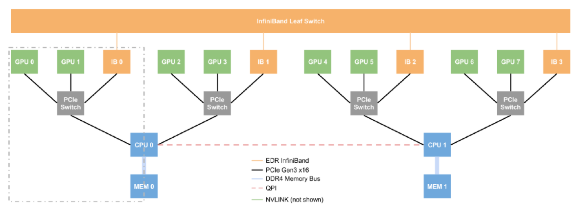
Notice that every two GPUs are connected to a single PCIe switch that is on the system board. The switch also connects to an InfiniBand (IB) network card. To reduce latency and improve throughput, and network traffic from these two GPUs should go to the associated IB card. This is why there are four IB cards in the DGX-1 appliance.
DGX-1 InfiniBand Networking
If you want to use the InfiniBand (IB) network to connect DGX appliances, theoretically, you only have to use one of the IB cards. However, this will push data traffic over the QPI link between the CPUs, which is a very slow link for GPU traffic (i.e. it becomes a bottleneck). A better solution would be to use two IB cards, one connected to each CPU. This could be IB0 and IB2, or IB1 and IB3, or IB0 and IB3, or IB1 and IB2. This would greatly reduce the traffic that has to traverse the QPI link. The best performance is always going to be using all four of the IB links to an IB switch.
The best approach for using IB links to connect all four IB cards to an IB fabric. This will result in the best performance (full bisectional bandwidth and lowest latency) if you are using multiple DGX appliances for training.
Typically, the smallest IB switch comes with 36-ports. This means a single IB switch could accommodate nine (9) DGX-1 appliances using all four IB cards. This allows 400 Gb/s of bandwidth from the DGX-1 to the switch.
For larger numbers of DGX-1 appliances, you will likely have to use two levels of switching. The classic HPC configuration is to use 36-port IB switches for the first level (sometimes called leaf switches) and connect them to a single large core switch, which is sometimes called a director class switch. The largest director class InfiniBand switch has 648 ports. You can use more than one core switch but the configuration will get rather complex. If this is something you are considering, please contact your NVIDIA sales team for a discussion.
For two tiers of switching, if all four IB cards per DGX-1 appliance are used to connect to a 36-port switch, and there is no over-subscription, the largest number of DGX-1 appliances per switch is 4. This is 4 ports from each DGX-1 into the switch for a total of 16. Then, there are 16 uplinks from the leaf switch to the core switch (the director class switch). A total of 40x 36-port leaf switches can be connected to the 648-port core switch (648/16). This results in 160 DGX-1 appliances being connected with full bi-sectional bandwidth.
You can also use what is termed over-subscription in designing the IB network. Over-subscription means that the bandwidth from an uplink is less than the bandwidth coming into the unit (in other words, poorer bandwidth performance). If we use 2:1 over-subscription from the DGX-1 appliances to the first level of switches (36-port leaf switches), then each DGX-1 appliance is only using two IB cards to connect to the switches. This results in less bandwidth than if we used all four cards and also higher latency.
If we keep the network bandwidth from the leaf switches to the core directory switch as 1:1 (in other words, no over-subscription, full bi-sectional bandwidth), then we can put nine (9) DGX-1 appliances into a single leaf switch (a total of 18 ports into the leaf switch from the DGX appliances and 18 uplink ports to the core switch). The result is that a total of 36 leaf switches can be connected to the core switch. This allows a grand total of 324 DGX-1 appliances to be connected together.
You can tailor the IB network even further by using over-subscription from the leaf switches to the core switch. This can be done using four IB connections to a leaf switch from each DGX appliance and then doing 2:1 over-subscription to the core switch or even using two IB connections to the leaf switches and then 2:1 over-subscription to the core switch. These designs are left up to the user to determine but if this is something you want to consider, please contact your NVIDIA sales team for a discussion.
Another important aspect of InfiniBand networking is the Subnet Manager (SM). The SM simply manages the IB network. There is one SM that manages the IB fabric at any one time but you can have other SM’s running and ready to take over if the first SM crashes. Choosing how many SM’s to run and where to run them can have a major impact on the design of the cluster.
The first decision to make is where you want to run the SM’s. They can be run on the IB switches if you desire. This is called hardware SM since it runs on the switch hardware. The advantage of this is that you do not need any other servers which could also run the SM. Running the SM on a node is called a software SM. A disadvantage to running a hardware SM is that if the IB traffic is large, the SM could have a difficult time. For lots of IB traffic and for larger networks, it is a best practice to use a software SM on a dedicated server.
The second decision to make is how many SM’s you want to run. At a minimum, you will have to run one SM. The least expensive solution is to run a single hardware SM. This will work fine for small clusters of DGX-1 appliances (perhaps 2-4). As the number of units grow, you will want to consider running two SM’s at the same time to get HA (High Availability) capability. The reason you want HA is that more users are on the cluster and having it go down has a larger impact than just a small number of appliances.
As the number of appliances grow, consider running the SM’s on dedicated servers (software SM). You will also want to run at least two SM’s for the cluster. Ideally, this means two dedicated servers for the SM’s, but there may be a better solution that solves some other problems; a head node.
DGX-1 Ethernet Networking
Each DGX-1 system comes with two 10Gb/s NICs. These can be used to connect the systems to the local network for a variety of functions such as logins and storage traffic. As a starting point, it is recommended to push NFS traffic over these NICs to the DGX-1. You should monitor the impact of IO on the performance of your models in this configuration.
If you need to go to more than one level of Ethernet switching to connect all of the DGX-1 units and the storage, be careful of how you configure the network. More than likely, you will have to enable the spanning tree protocol to prevent loops in the network. The spanning tree protocol can impact network performance, therefore, you could see a decrease in application performance.
The InfiniBand NICs that come with the DGX-1 can also be used as Ethernet NICs running TCP. The ports on the cards are QSFP28 so you can plug them into a compatible Ethernet network or a compatible InfiniBand network. You will have to add some software to the appliance and change the networking but you can use the NICs as 100GigE Ethernet cards.
For more information, see Switch InfiniBand and Ethernet in DGX-1.
DGX-1 Bonded NICs
The DGX-1 provides two 10GbE ports. Out of the factory these two ports are not bonded but they can be bonded if desired. In particular, VLAN Tagged, Bonded NICs across the two 10 GbE cards can be accomplished.
- Ensure your network team is involved because you will need to choose a bonding mode for the NICs.
- Ensure you have a working network connection to pull down the VLAN packages. To do so, first setup a basic, single NIC network (no VLAN/bonding) connection and download the appropriate packages. Then, reconfigure the switch for LACP/VLANs.
- Edit the /etc/network/interfaces file to setup an interface on a
standard network so that we can access required packages.
auto em1
	iface em1 inet static
	   address 10.253.0.50
 	   netmask 255.255.255.0
 	   network 10.253.0.0
 	   gateway 10.253.0.1
 	   dns-nameservers 8.8.8.8
- Bring up the updated
interface.
sudo ifdown em1 && sudo ifup em1
- Pull down the required bonding and VLAN
packages.
sudo apt-get install vlan
sudo apt-get install ifenslave
- Shut down the
networking.
sudo stop networking
- Add the following lines to /etc/modules to load appropriate drivers.
sudo echo "8021q" >> /etc/modules
sudo echo "bonding" >> /etc/modules
- Load the
drivers.
sudo modprobe 8021q
sudo modprobe bonding
- Reconfigure your /etc/network/interfaces file. There are some
configuration parameters that will be customer network dependent and you will want to work
with one of your network engineers.
The following example creates a bonded network over em1/em2 with IP 172.16.1.11 and VLAN ID 430. You specify the VLAN ID in the NIC name (bond0.###). Also notice that this example uses a bond-mode of 4. Which mode you use is up to you and your situation.
auto lo
iface lo inet loopback


# The following 3 sections create the bond (bond0) and associated network ports (em1, em2)
auto bond0
iface bond0 inet manual
bond-mode 4
bond-miimon 100
bond-slaves em1 em2

auto em1
iface em1 inet manual
bond-master bond0
bond-primary em1

auto em2
iface em2 inet manual
bond-master bond0


# This section creates a VLAN on top of the bond.  The naming format is device.vlan_id
auto bond0.430
iface bond0.430 inet static
address 172.16.1.11
netmask 255.255.255.0
gateway 172.16.1.254
dns-nameservers 172.16.1.254
dns-search company.net
vlan-raw-device bond0
- Restart the networking.
sudo start networking
- Bring up the bonded interfaces.
ifup bond0
- Engage your network engineers to re-configure LACP and VLANs on switch.
- Test the configuration.
DGX-2 Networking
Because there are more network devices in the DGX-2 relative to the DGX-1 and DGX Station, and they can be used in different ways, to learn more about DGX-2 networking, see the DGX-2 User Guide.