Flashing Support for Jetson Thor#
Use l4t_initrd_flash.sh to flash a Jetson device. You can flash with initrd (initial RAM disk) to both internal media and external media connected to a Jetson device. The procedure uses initrd
and USB device mode.
Tools and instructions for flashing with initrd can be found in the
directory /Linux_for_Tegra/tools/kernel_flash/. For more detailed
information, see README_initrd_flash.txt in the same directory.
README_initrd_flash.txt contains examples several workflows that flash
with initrd:
Flashing internal storage devices
Flashing external storage devices such as NVMe SSD and USB drives
Enabling A/B rootfs on external storage devices
Enabling disk encryption on external storage devices
Flashing individual partitions
Flashing fused Jetson devices.
Flashing a Massflash blob to normal and fused Jetson devices
Generating separate images for external and internal storage devices, then flashing the combined images
By default, the board configuration and the partition layout support external media with a storage capacity of at least 64 GB. To accommodate external media that have storage capacity, you need to modify the ROOTFSSIZE variable in the board configuration and the num_sectors field in the partition layout. For more information on how to modify the partition layout for external storage devices, see Partition Configuration.
Before You Begin#
The following directories must be present:
bootloader: Bootloader plus flashing tools, such as TegraFlash, CFG, and BCT.kernel: A kernel image/Image, DTB files, and kernel modules.rootfs: The root file system that you downloaded.This directory starts empty. You populate it with the sample file system.
nv_tegra: User space binaries and sample applications.
Additionally, before running these commands, you must use a USB cable to connect your host computer to the Jetson device’s recovery port.
Initrd flash requires a high-quality USB-C / micro-USB cable. A low-quality cable might make the flashing process fail.
To install the correct dependencies, run the following script:
$ sudo tools/l4t_flash_prerequisites.sh # For Debian-based Linux
Basic Flashing Script Usage#
Display the current usage information for l4t_initrd_flash.sh by running l4t_initrd_flash.sh –h, using the script included in the release. The syntax is as follows:
$ sudo ./l4t_initrd_flash.sh [<options>] <board> <rootdev>
optionsis one or more command-line options. No options are required. For more information, see Flashing Script Usage.<board>specifies the configuration to be applied to the device to be flashed. Values are listed in the Jetson Modules and Configurations table in Quick Start.l4t_initrd_flash.shgets the configuration from a configuration file named<board>.conf.<board>.confspecifies the location of a partition layout file which specifies what storage devices are flashed on the Jetson target. For more detailed explanation of<board>.conf, see Explaining Board Configuration File and Generating a Flash Image to Flash Later .<rootdev>specifies the type of device to be used as the root file system. For most use cases, you should use the valueinternalto specify a local storage device (NVMe SSD or UFS) as the root file system.
Basic Flashing Procedures#
This section describes some common procedures for flashing one or more target devices.
Installing the Flash Requirements#
Run the following command:
$ sudo tools/l4t_flash_prerequisites.sh
Flashing the Target Device#
Put the target device into Force Recovery Mode.
Power on the carrier board and hold down the RECOVERY button.
Press the RESET button.
Run the
tools/kernel_flash/l4t_initrd_flash.shscript that is in the top-level directory of BSP for this release. The command line must specify the target board (for example,jetson-agx-thor-devkit) for the root file system:$ sudo ./l4t_initrd_flash.sh <board> <rootdev>
<board>specifies the configuration of the target device, as described by the Jetson Modules and Configurations table in Quick Start.<rootdev>specifies the device on which the root file system is located, as described in Basic Flashing Script Usage.
For example, run the script like this:
$ sudo ./l4t_initrd_flash.sh <board> internal
Flashing by Using a Convenient Script#
NVIDIA provides a convenient flashing script that automatically detects the Jetson device’s type of carrier board:
$ sudo ./nvsdkmanager_flash.sh [--storage <storage> ]
The value of <storage> can be nvme0n1p1 or nvme1n1p1 for flashing to an external NVMe SSD, sda1 for flashing to an external USB storage drive, or mmcblk0p1 or mmcblk1p1 for flashing to an external SD card, depending on the target device.
Without --storage option, the Jetson device’s default storage is flashed.
Explaining Board Configuration File and Generating a Flash Image to Flash Later#
The board configuration file (<board>.conf) is a bash script that defines several bash variables. These variables specify the Boot Configuration Table (BCT), Device Tree Blob (DTB), kernel, configuration files, firmware, and partition layout to be used by flash.sh.
The board configuration file specifies partition configuration files that describe the storage devices that are flashed by the flashing tool and the partition layouts on those storage devices. It uses the following variables:
EMMC_CFG: Specifies the partition configuration file that describes both the internal storage device and the partition layout for the internal storage device. This variable is required.
EXTERNAL_PT_LAYOUT: Specifies the default partition configuration file that describes only the partition layout for the external storage device. The external storage device to be flashed is specified in theEXTERNAL_DEVICEvariable or the--external-deviceoption. This variable is optional; you can provide the information by using the-coption instead.
EXTERNAL_DEVICE: Specifies the default external storage device to be flashed for theEXTERNAL_PT_LAYOUTvariable. This variable is optional.
For more information about the format of the partition configuration file, see Partition Configuration.
Typically, NVIDIA-provided board configurations rely on values retrieved from EEPROM and the chip to define these bash variables. To generate a flash image for later flashing:
Place the Jetson target into recovery mode.
Use this command to retrieve the EEPROM and chip information from the board, and to subsequently generate a flash image:
$ sudo ./l4t_initrd_flash.sh --no-flash <board> internal
When the Jetson target in recovery mode is unavailable, you can still generate a flash image by using EEPROM and chip values obtained manually through environment variables. For example:
$ sudo BOARDSKU=0000 FAB=500 BOARDREV=500 CHIP_SKU=D0 RAMCODE=0 FUSELEVEL=fuselevel_production ./l4t_initrd_flash.sh --no-flash jetson-agx-thor-devkit mmcblk0p1
Such information is usually available on the Jetson target specification sheet. Alternatively, it can be retrieved manually if you have physical access to the Jetson target:
Place the Jetson target into recovery mode.
Run this command to generate
bootloader/ecid.bin:$ sudo ./flash.sh --no-flash --no-systemimg <board> mmcblk0p1Retrieve the environment variables above using these commands:
$ cat bootloader/ecid.bin
After generating the flash image, you can proceed with flashing at a later time using this command:
$ sudo ./l4t_initrd_flash.sh --flash-only <board> internal
Backing Up and Restoring a Jetson Device#
NVIDIA provides tools for creating a backup image of a Jetson device and restoring the device from a backup image.
The tools for backing up and restoring a Jetson device are in this directory in the BSD:
/Linux_for_Tegra/tools/backup-restore/
Instructions for backing up and restoring a device are in the file README_backup_restore.txt in the same directory.
The time it takes to back up or restore a partition depends on the size of the partition.
Flashing Script Usage#
This section complements Basic Flashing Script Usage by providing detailed information about l4t_initrd_flash.sh command-line options and other aspects of l4t_initrd_flash.sh usage.
Option/Argument |
Description |
|---|---|
-u <PKC key file> |
PKC key used for ODM fused board. |
-v <SBK key file> |
SBK key used for encryption. |
-p <options> |
Pass specified options to |
-k <target_partition> |
Flash only the specified partition. |
-P <dir> |
Specify the output directory when generating a flash package for Jetson Thor devices. |
<board-name> |
Specify the board to use. |
<rootdev> |
Specify the root device to use. |
--no-flash |
Generate the flash images. |
--flash-only |
Flash using existing images. |
--external-device <dev> |
Generate or flash images for the specified external storage device. If this is used, the |
--external-only |
Skip generating internal storage images. |
--usb-instance |
Specify the USB port where the flashing cable is connected (such as 1-3). |
--sparse |
Use sparse image to flash instead of tar image. |
-c <config file> |
The partition layout for the external storage device. |
-S <size> |
Size of the external APP partition in bytes. KiB, MiB, and GiB shorthand notation is allowed; for example, |
--massflash [<max_devices>] |
Flash multiple devices. Optionally specify |
--showlogs |
Spawn gnome-terminal to show individual flash process logs. Applicable for |
--reuse |
Reuse existing working environment kept by |
--keep |
Keep working environment instead of cleaning up after flashing. |
--erase-all |
Erase all storage devices before flashing. |
--initrd |
Stop after device boots into initrd. |
--network <netargs> |
Flash through Ethernet protocol using initrd flash.
|
--append |
Used only with
|
--direct <dev> |
Flash specified device directly connected to host. Example:
|
--with-systemimg |
Generate system image even when flashing individual partition. |
--pv-enc <key_file> |
The key to encrypt cpu_bootloader. |
--pv-crt <crt_file> |
The certificate for the key used to sign cpu_bootloader. |
-i <enc_rfs_key_file> |
Key for disk encryption support. |
--uefi-keys <keys_conf> |
Specify UEFI keys configuration file. |
--uefi-enc <uefi_enc_key> |
Key file (0x19: 16-byte; 0x23: 32-byte) to encrypt UEFI payloads. |
--odm-image-gen |
Generate ODM payload. |
--mass-storage-only |
Generate OEM payload for NVMe or eMMC. |
--qspi-only |
Generate or flash only the QSPI package. |
--profile |
Specify a chip mapping profile. |
--with-systemimg |
Generate system image even when flashing individual partition. |
--pv-enc <key_file> |
The key to encrypt cpu_bootloader. |
--pv-crt <crt_file> |
The certificate for the key used to sign cpu_bootloader. |
-i <enc_rfs_key_file> |
Key for disk encryption support. |
--ekb-pair |
Flash EKB that corresponds to the serial number of the target. |
--boot-rootfs |
Use flashing kernel initrd to mount |
--hsm |
Enable HSM for image signing/encryption. |
--read-ramcode |
Generate |
The -p option supports the following options:
Option |
Description |
|---|---|
-b <emc_bctfile> |
Use the specified emc_bct file. |
-c <cfgfile> |
Flash partition table config file. |
-e <bpmp_file> |
Use the specified bpmp file. |
-g <bpmp_dtb_file> |
Use the specified bpmp DTB file. |
-l <tbcdtbfile> |
CPU bootloader DTB file. |
-m <mts_preboot> |
MTS preboot, such as |
-o <odmdata> |
ODM data. |
-w <wb0boot> |
Warm boot binary, such as |
-L <bootloader> |
Bootloader, such as |
-M <mts_boot> |
MTS boot file, such as |
-U <int_num_sectors> |
The number of sectors of the internal storage device. Default is 119537664. |
--boot-chain-flash <c> |
Flash only the specified boot chain (such as |
--boot-chain-select <c> |
Specify boot chain (such as |
--reuse-uuid |
Reuse previously generated UUID. |
--passthrough |
Additional options to pass to the |
--debug |
Enable debug mode and |
The flash script supports some environment variables to override the default behavior.
Environment Variable |
Description |
|---|---|
EXTOPTIONS |
Flash options when generating flash image for external devices. Supports the same options as the |
FLASHING_KERNEL |
Defines the path of the initrd image used for running the flashing process. |
ERASE_QSPI |
Bricks the device when running with |
ADDITIONAL_DTB_OVERLAY_OPT |
Defines the path of the additional DTB overlay file. |
EXTOPTIONS supports the following options:
Option |
Description |
|---|---|
-d <dtbfile> |
Device tree file. |
-n <nfs_args> |
Static NFS network assignments: |
-r |
Skip building and reuse existing |
-C <cmdline> |
Kernel command-line arguments. WARNING: Each option gets higher preference over |
-N <nfsroot> |
NFS root path ( |
-R <rootfs_dir> |
Sample rootfs directory. |
-T <ext_num_sectors> |
Number of sectors of external storage device. Default is 119537664. |
-K <kernel> |
Kernel image file, such as zImage or Image. |
--uda-dir |
Directory to store user data that will be encrypted in UDA partition. |
--generic-passphrase |
Use generic passphrase for disk encryption. |
--disable-random-iv |
Disable generation of random IV, SALT1, SALT2, and DERSTR. |
--reuse-uuid |
Reuse previously generated UUID. |
--no-systemimg |
Do not create or re-create |
--passthrough |
Additional options to pass to the |
--debug |
Enable debug mode and |
Finding the USB Instance#
The flash.sh script supports the --usb-instance options to flash a specific Jetson device on a host that has multiple devices in recovery mode. This section provides information about determining which USB instance to use.
Place all devices in recovery mode.
Run the following command:
$ grep <idProduct> /sys/bus/usb/devices/*/idProduct
idProductis the USB ID for recovery mode of the device. For example, 7026 is for Jetson Thor.The result will be something like the following:
/sys/bus/usb/devices/1-1.1/idProduct:7023
1-1.1 is the usb-instance number you want to use to specify which device you want to flash
Flashing to a USB Drive#
Jetson devices can be booted from a mass storage–class USB device with bulk-only protocol, such as a flash drive. Hot plugging is not supported; the flash drive must be attached before the Jetson device is booted. You can manually set up a flash drive for booting as explained in To set up a flash drive manually for booting.
All Jetson devices can boot from internal storage using a boot partition and can mount an external USB drive as the root file system.
NVIDIA provides a way to simplify flashing to a USB drive that is connected to a Jetson device. For details, see To set up a USB drive as a boot device or root file system using flash with initrd.
Manually Setting Up a Flash Drive for Booting#
Confirm that the device can boot successfully into the UEFI menu. If it cannot, correct the problem by flashing the QSPI of the device.
Connect the flash drive to the host computer.
Determine the flash drive’s device name (such as
/dev/sdb):$ sudo lsblk -p -d | grep sd
Run the command:
$ sudo <env-var> ./l4t_initrd_flash.sh [ -S <rootfssize> ] -c <config> --external-device sda1 --direct <sdx> <board> external
In this command,
<sdx>is the device name that your host computer assigned to the flash drive.<config>is the USB partition layout. For an example, seeLinux_for_Tegra/tools/kernel_flash/flash_l4t_t264_nvme.xml.<board>is the type of Jetson device to be flashed. See the Jetson Modules and Configurations table in Quick Start.You can also specify
<rootfssize>as the size of the APP partition. This value is different from the total size of the external storage device, which is defined by the num_sectors field in<config>. If you change the num_sectors field in<config>, you have to specify a new<rootfssize>so that it is a few GiB smaller then the total size of the external storage device to fit the APP and other partitions.If you run the command without a device in recovery mode plugged in, you must specify it.
For example, if the host computer assigns the flash drive device name
sdb, the command for Jetson Thor is the following:$ sudo ./l4t_initrd_flash.sh -c tools/kernel_flash/flash_l4t_t264_nvme.xml --external-device sda1 --direct sdb jetson-agx-thor-devkit external
By default,
Linux_for_Tegra/tools/kernel_flash/flash_l4t_t264_nvme.xmlsupports only 64-GiB or larger SD cards. If you want to flash a 32-GiB SD card, you must modify the num_sectors field inLinux_for_Tegra/tools/kernel_flash/flash_l4t_t264_nvme.xmlso that num_sectors * 512 = 32 GiB. The command to run is as follows:$ sudo ./l4t_initrd_flash.sh -c tools/kernel_flash/flash_l4t_t264_nvme.xml -S 20GiB --external-device sda1 --direct sdb jetson-agx-thor-devkit external
You must specify
<rootfssize>as 20GiB so that the value is smaller than the SD card size.Note
For more information, read Workflow 11 in the README_initrd_flash.txt file, which is in the
Linux_for_Tegra/tools/kernel_flashdirectory.Plug the flash drive into the target device.
Turn on or reboot the target device.
You might need to modify the UEFI’s boot-order using
efibootmgror UEFI GUI.
Setting Up a USB Drive as a Boot Device or Root File System using Flash with initrd#
By flashing with initrd you can flash to an external USB device attached to a Jetson device. For more information, see Partition Configuration.
Flashing to an NVMe Drive#
Jetson devices can be booted from an NVMe drive. Hot-plugging is not supported; the NVMe drive must be attached before the Jetson device is booted.
You can manually set up an NVMe drive for booting by following the steps in To set up an NVMe drive manually for booting.
All Jetson devices can boot from internal storage using a boot partition and mount an external NVMe drive as the root file system.
NVIDIA provides a way to simplify flashing to an NVMe drive that is connected to a Jetson device. For details, see To set up an NVMe drive as a boot device or root file system using flash with initrd.
Manually Setting Up an NVMe Drive for Booting#
Confirm that the device can boot into the UEFI menu. If it cannot, correct the problem by flashing the QSPI of the device.
Connect the flash drive to the host computer.
Determine the NVMe drive’s device name (such as
/dev/nvme0n1):$ lsblk -d -p | grep nvme | cut -d\ -f 1
Note that there must be two spaces after the
-d\.Run the command:
$ sudo <env-var> ./l4t_initrd_flash.sh [ -S <rootfssize> ] -c <config> --external-device nvme0n1p1 --direct <nvmeXn1> <board> external
In this command,
<nvmeXn1>is the device name that your host computer assigns to the NVMe drive.<config>is the NVMe SSD partition layout. For an example, seeLinux_for_Tegra/tools/kernel_flash/flash_l4t_t264_nvme.xml.<board>is the type of Jetson device to be flashed. See the Jetson Modules and Configurations table in Quick Start.You can also specify
<rootfssize>as the size of the APP partition. This value is different from the total size of the external storage device, which is defined by the num_sectors field in<config>. If you change the num_sectors field in<config>, you have to specify a new<rootfssize>so that it is a few GiB smaller then the total size of the external storage device to fit the APP and other partitions.If you run the command without a device in recovery mode plugged in, you must specify it.
For example, if the host computer assigns the flash drive device name
nvme1n1p1, the command for Jetson Thor is the following:$ sudo ./l4t_initrd_flash.sh -c tools/kernel_flash/flash_l4t_t264_nvme.xml --external-device nvme0n1p1 --direct nvme1n1p1 jetson-agx-thor-devkit external
Note
For more information, read Workflow 11 in the README_initrd_flash.txt file, which is in the
Linux_for_Tegra/tools/kernel_flashdirectory.Plug the flash drive into the target device
Turn on or reboot the target device.
If your device still boots from its internal storage, you might need to modify the UEFI’s boot-order using
efibootmgror the UEFI GUI.
Setting Up an NVMe Drive as a Boot Device or Root File System using Flash with initrd#
By flashing with initrd you can flash to an external NVMe SSD attached to a Jetson device. For more information, see Partition Configuration.
Flashing a Specific Partition#
You can flash a specific partition instead of flashing the whole device
by using the command line option -k.
Prepare the workspace with necessary files (only once):
$ sudo ./l4t_initrd_flash.sh --no-flash <board> <rootdev>
Enter the following command:
$ sudo ./l4t_initrd_flash.sh -k <partition_name> <board> <rootdev>
In this command,
<partition_name>is the name of the partition to be flashed. Possible values depend on the target device. For specific filenames, see the table of Partition Configuration Files.<board>is the configuration of the target device as specified in the Jetson Modules and Configurations table in Quick Start.<rootdev>specifies the device on which the root file system is located, as described in Basic Flashing Script Usage.
Examples#
Prepare the workspace with necessary files:
$ sudo ./l4t_initrd_flash.sh --no-flash jetson-agx-thor-devkit mmcblk0p1
To flash A_MB1_BCT on a Jetson Thor device using a predefined list of configuration files:
$ sudo ./l4t_initrd_flash.sh -k A_MB1_BCT jetson-agx-thor-devkit mmcblk0p1
To flash only QSPI on a Jetson Thor device:
$ sudo ./l4t_initrd_flash.sh --qspi-only jetson-agx-thor-devkit mmcblk0p1
To flash only NVMe SSD:
$ sudo ./l4t_initrd_flash.sh --external-only --external-device nvme0n1 -c tools/kernel_flash/flash_l4t_t264_nvme.xml <board> <rootdev>
To flash APP partition in the NVMe:
$ sudo ./l4t_initrd_flash.sh --external-only -k APP --external-device nvme0n1 -c tools/kernel_flash//flash_l4t_t234_nvme.xml <board> <rootdev>
Flashing for NFS as Root#
You can flash the device to use a network file system (NFS) as the root file system.
Flashing for a Network File System as a Root File System#
Put the device into recovery mode: Power the carrier board on, press and hold the RECOVERY button, and then press the RESET button.
Enter the following command:
$ sudo EXTOPTIONS="-N <ip_addr>:<root_path>" ./l4t_initrd_flash.sh --external-device <storage-device> -c <external-board-config> -p "-N <ip_addr>:<root_path>" <board> eth0
In this command,
<storage-device>is the external storage device that is attached to the Jetson device. For example,--external-device nvme0n1p1specifies an NVMe SSD attached to Jetson Thor.<external-board-config>is the external board configuration file for the storage device attached to the Jetson device. For example,-c tools/kernel_flash/flash_l4t_t264_nvme.xmlis the file for an NVMe SSD attached to Jetson Thor.<ip_addr>is the IP address of the host system.<root_path>is the path to the NFS root file system.<board>is the configuration of the target device as specified in the Jetson Modules and Configurations table in Quick Start.
The command flashes Bootloader and a file system image with a
/bootdirectory only to use the network file system at<ip_addr>:/<root_path>as the root file system at boot time.
Cloning rootfs with initrd#
Put the Jetson device in Recovery Mode.
Enter these commands on the host:
$ cd Linux_for_Tegra
$ sudo ./l4t_initrd_flash.sh --boot-rootfs --initrd <board-name> <rootdev>
In the preceding command,
<board-name>is the value of the environment variableBOARDfor the target device. See the Jetson Modules and Configurations table in Quick Start.<rootdev>specifies the device on which the root file system is located, as described in Basic Flashing Script Usage.
Enter bash shell on the Jetson device.
Plug a USB drive into the Jetson device and clone the rootfs partition as an exact copy of
system.img.rawinto this USB drive by running the following commands:$ mount /dev/sda1 /mnt $ dd if=<rootfs partition> of=/mnt/system.img.raw $ sync $ umount /mnt
The value
/dev/sda1specifies the plugged-in USB drive. The<rootfs partition>might be/dev/mmcblk0p1for an eMMC device or/dev/nvme0n1p1for an NVMe device.Unplug the USB drive from the Jetson device and plug it into the host machine.
Copy the
system.img.rawfile from the USB drive to the host machine.Convert it to the
system.imgsparse image by running the following command:$ cd Linux_for_Tegra $ ./bootloader/mksparse --fillpattern=0 system.img.raw system.img
Flash
system.imgto the target device:$ sudo EXTOPTIONS="-r" ./l4t_initrd_flash.sh jetson-agx-thor-devkit nvme0n1p1
Bringing Up the Jetson Module for the initrd Flash Tool#
The initrd flash tool is validated to work with NVIDIA developer kits. For this tool to work on your custom carrier board with Jetson modules, ensure that a USB device mode has been enabled for your custom carrier board.
Often you need to customize the BSP. In some cases, customization might cause the BSP to fail to initrd flash the device. For these cases, initrd flash supports a separation of flashing environment and the content that is flashed:
Create a new board configuration file that exposes the USB device mode for your custom carrier board, such as
board_config_for_flashing.cfg.Add the following line to your main board configuration file:
FLASH_CONFIG_FILE=board_config_for_flashing.cfg
# Additionally you can provide your own boot image for the flashing kernel. For example:
# _FLASHING_KERNEL="${LDK_DIR}/unified_flash/tools/flashtools/flashing_kernel/initramfs/t264/boot_flashing.img"
Run the initrd flash command. The unified flash tool generates the flashing environment using
board_config_for_flashing.cfgand the content for flashing using your main board configuration file.
Flashing to Multiple Jetson Devices#
NVIDIA provides a tool and instructions to efficiently flash Jetson devices in a factory environment. To flash to multiple Jetson devices with this tool, generate the massflash package using the --no-flash and --massflash <x> options, where <x> is the highest possible number of devices that will be concurrently flashed.
Both online mode and offline mode are supported. In the following example, the offline mode is used to create a flashing environment that can concurrently flash five devices:
$ sudo BOARDID=<boardid> FAB=<fab> BOARDSKU=<boardsku> BOARDREV=<boardrev> CHIP_SKU="00:00:00:xx" ./l4t_initrd_flash.sh --no-flash --massflash 5 jetson-agx-thor-devkit mmcblk0p1
For the values of BOARDID, FAB, BOARDSKU, and BOARDREV, refer to Devices Supported by This Document, /Linux_for_Tegra/tools/kernel_flash/README_initrd_flash.txt, and Explaining Board Configuration File and Generating a Flash Image to Flash Later.
Connect the five Jetson devices to the flashing hosts.
Ensure that the devices have the same hardware revision.
Place all connected Jetson devices into RCM mode.
Run the following command:
$ sudo ./l4t_initrd_flash.sh --flash-only --massflash 5
# Optionally add --showlogs to show all of the log
Note
The actual number of connected devices can be less than the maximum number of devices the package can support.
When you use this tool, remember the following tips:
The tool provides the
--keepoption to keep the flash environment, and the--reuseoptions to reuse the flash environment, which makesmassflashrun faster:For the initial mass flash:
$ sudo ./l4t_initrd_flash.sh --flash-only --massflash 5 --keep
For subsequent mass flash attempts:
$ sudo ./l4t_initrd_flash.sh --flash-only --massflash 5 --reuse
Use
ioniceto make the flash process the highest I/O priority in the system:$ sudo ionice -c 1 -n 0 ./l4t_initrd_flash.sh --flash-only --massflash 5
If mass flashing with UEFI secure boot enabled, refer to Workflow 8 in
<Linux_for_Tegra>/tools/kernel_flash/README_initrd_flash.txt. For example, to mass flash with UEFI payload encryption:$ sudo ./l4t_initrd_flash.sh –flash-only –massflash 5 –uefi-keys uefi_keys.conf –uefi-enc uefi_payload_encryption.key
Flashing to Jetson Without Reading EEPROM#
Sometimes when you update the customer over-writable section of the EEPROM, a mistake can cause the CRC-8 to be incorrect. In this case, you might have issues being able to flash and boot the system. To skip the EEPROM read during flashing, run the following command:
$sudo SKIP_EEPROM_CHECK=1 BOARDID=<BOARDID> BOARDSKU=<BOARDSKU> ./l4t_initrd_flash.sh <board> <rootdev>
For more information about the BOARDID and BOARDSKU values, refer to Devices Supported by This Document and <Linux_for_Tegra>/tools/kernel_flash/README_initrd_flash.txt.
After the board is flashed and boots up, to correct the EEPROM content, complete the following steps:
Use the Linux i2c-tools to correct corrupted EEPROM content.
Dump the complete EEPROM content with i2c-tools.
Calculate the CRC8 value based on the result from step 2.
Write the CRC8 value to byte 255 in EEPROM.
For more information about EEPROM content and calculating CRC8, refer to Jetson EEPROM Layout.
Note
This method should be used only for the CRC-8 checksum bit corruption in EEPROM. If your module has another faulty EERPOM or I2C, consider using RMA instead of this method.
Determining the Success of a Driver Update#
After updating drivers on a target board, verify that the update completed successfully. You can determine the success or failure of a driver update by using the following commands.
Determining the Success of a Driver Update#
Execute this command on a booted target device:
$ sha1sum –c /etc/nv_tegra_release
If the driver update succeeded, the command displays OK after the file name. A typical success message looks like this:
/usr/lib/xorg/modules/drivers/nvidia_drv.so: OK
The driver update fails if the file is missing. A typical error message looks like this:
sha1sum: /usr/lib/xorg/modules/drivers/nvidia_drv.so: No such file or directory
/usr/lib/xorg/modules/drivers/nvidia_drv.so: FAILED open or read
The driver update also fails if the new file is different from the existing file, producing an error such as the following:
/usr/lib/xorg/modules/drivers/nvidia_drv.so: FAILED
Configuring a Jetson Device with NVIDIA OOBE#
A target device that is flashed by SDK Manager runs the NVIDIA OOBE tool automatically the first time it boots after it is flashed. You can use this tool to change some parts of the device configuration such as username and password, language, and time zone.
On a headed target device (one equipped with a display), NVIDIA OOBE runs the Gnome Initial Setup application. On a headless target device (one without a display), it runs oem-config as a character interface application that communicates through the flashing port with a terminal program running on the host.
Headed Mode Flow in System Configuration#
Before the target system boots for the first time, you must connect a display via DisplayPort or HDMI. NVIDIA OOBE will run Gnome Initial Setup application for system configuration.
Note
After Gnome Initial Setup is started, system configuration must be completed in headed mode, even if the system is accidentally restarted during the process.
Configuring the Target Device with Gnome Initial Setup#
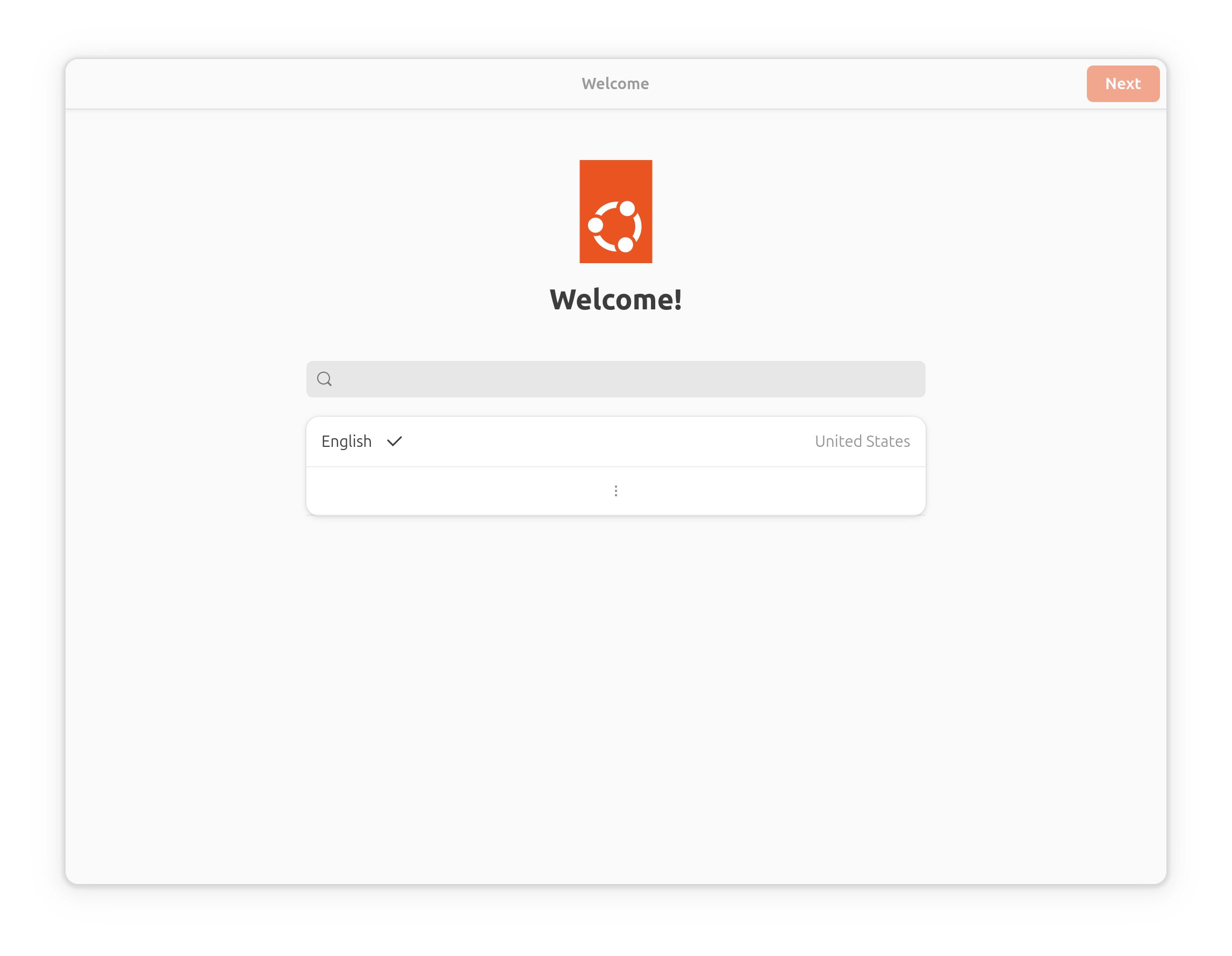
Gnome Initial Setup displays a welcome screen. To advance to the next screen, click the Next button.
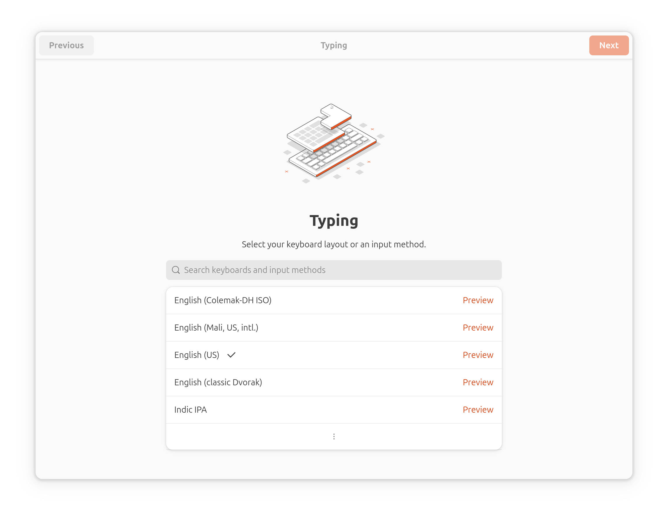
Gnome Initial Setup lists the keyboard layouts. Select your keyboard layout; then click the Next button.
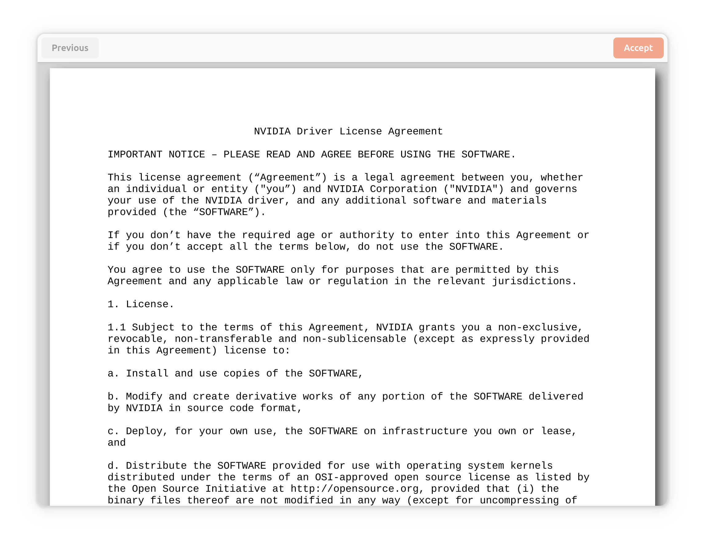
Gnome Initial Setup displays the license that governs its use. Read the license and accept it by clicking the Accept button.
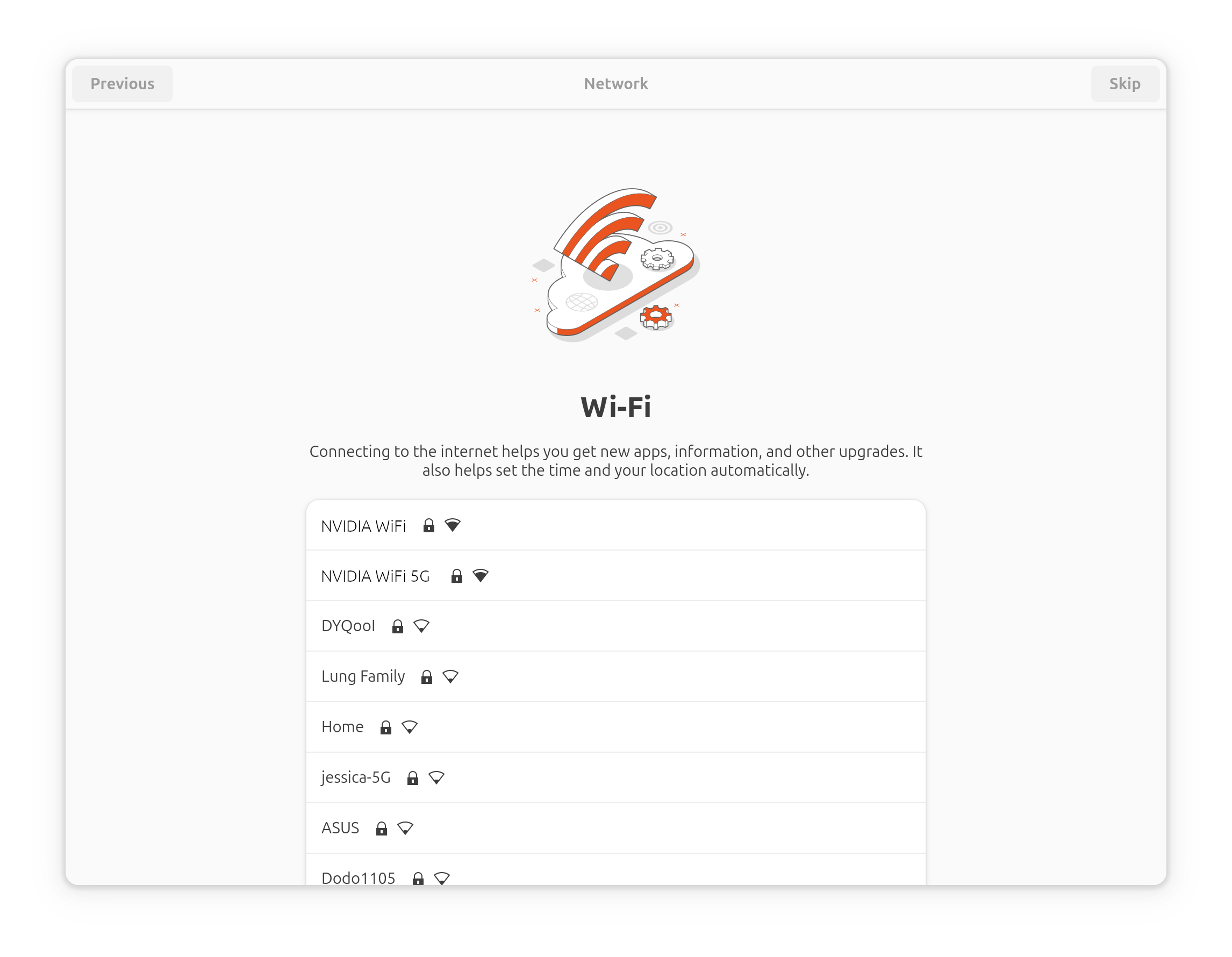
Gnome Initial Setup lists available Wi-Fi access points. Select a Wi-Fi access point to configure, or click the Skip button to skip Wi-Fi configuration.
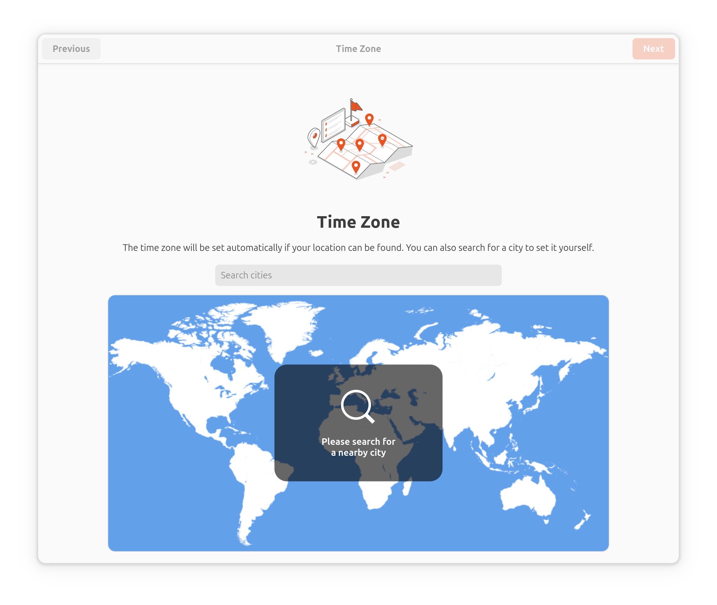
Gnome Initial Setup shows the world map. Click the map to select a nearby city, or enter a city name in the Search cities field to select a nearby city; then click the Next button.
Gnome Initial Setup asks for details about the current device. Enter Full Name, Username, and Computer as hostname; then click the Next button.
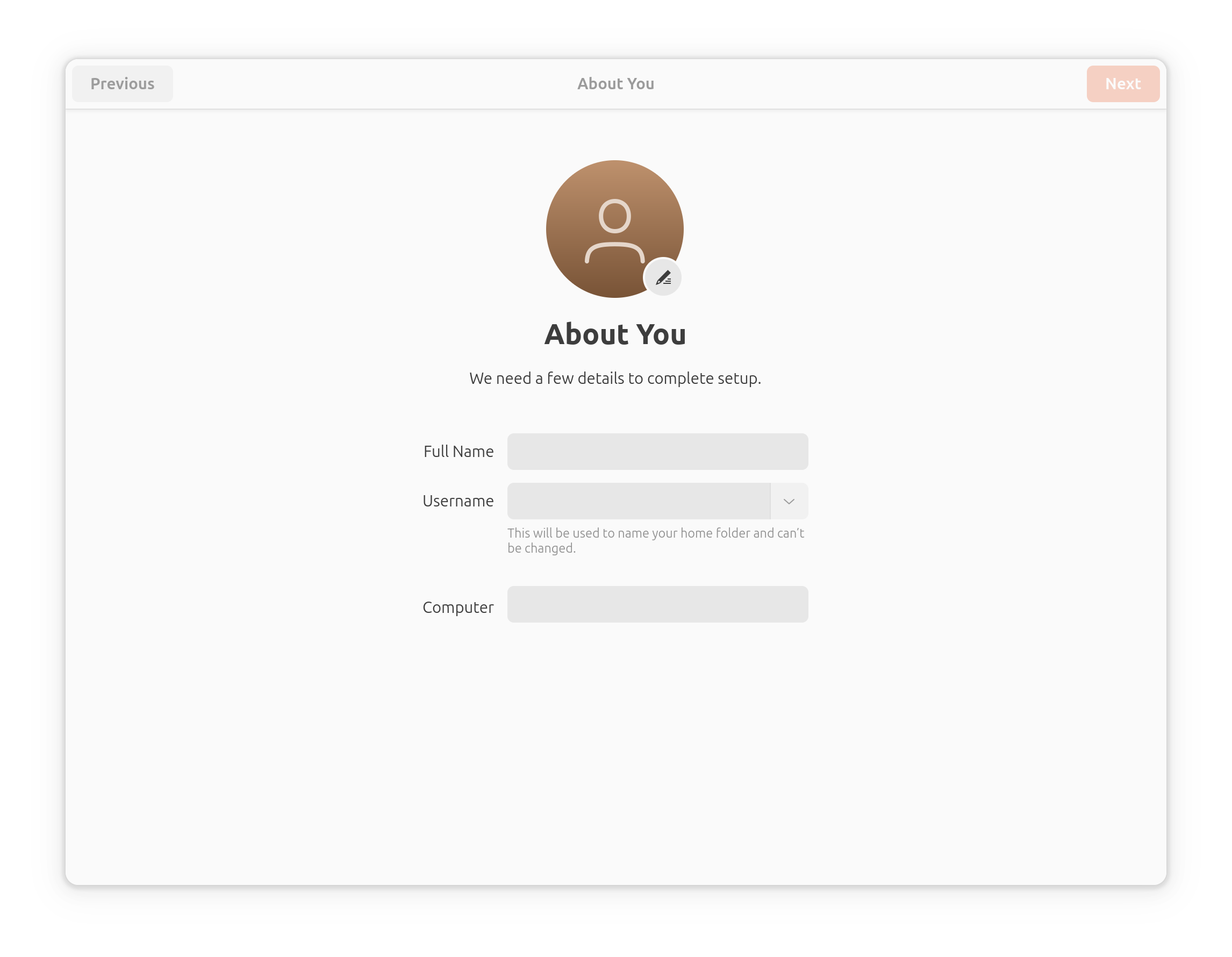
Note
The hostname must be unique within the local network. Clicking Next completes the hostname setup. If you click Previous to return to this page and set up the hostname again, the same hostname cannot be used.
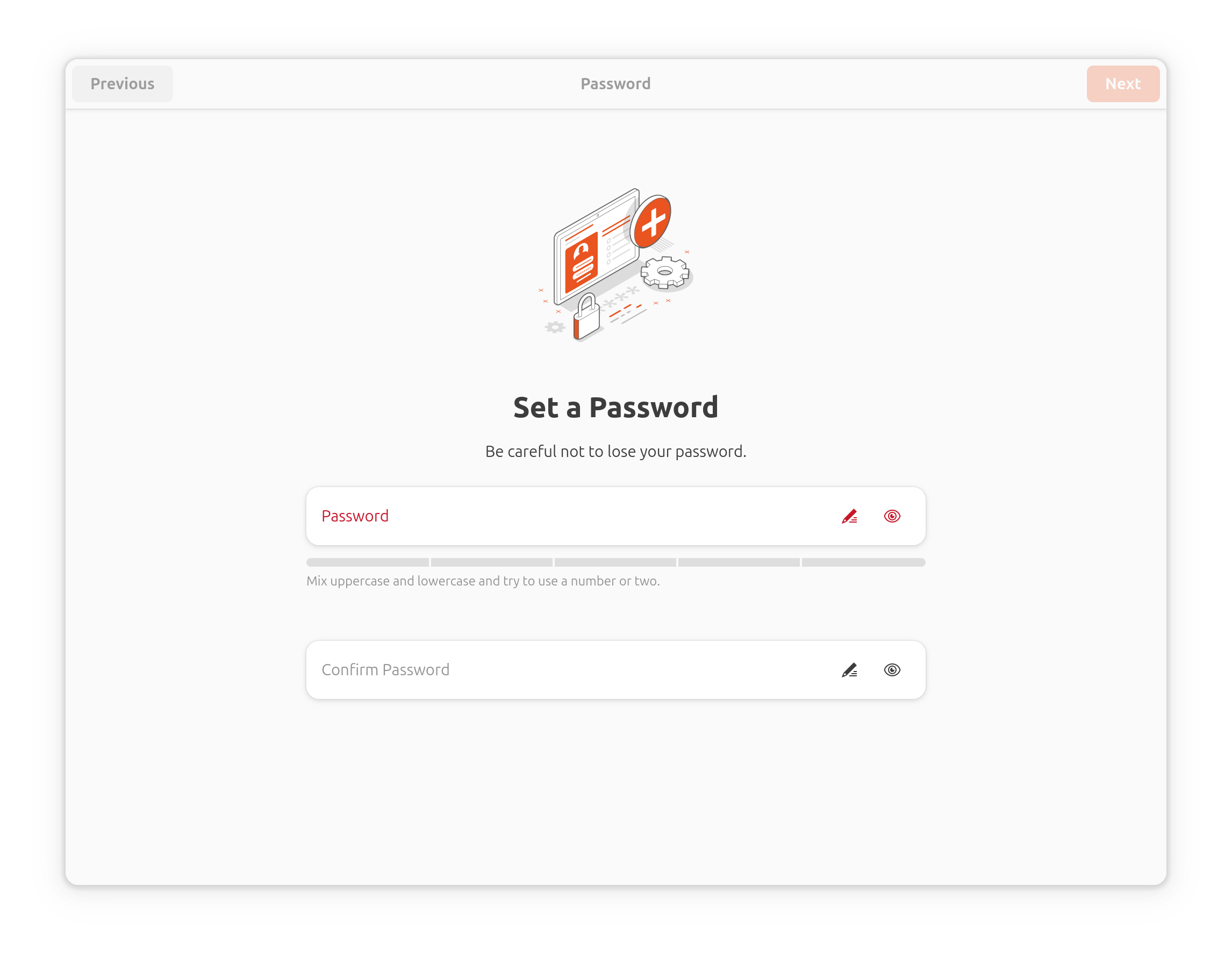
Gnome Initial Setup requests a password. Enter the password; then click the Next button.
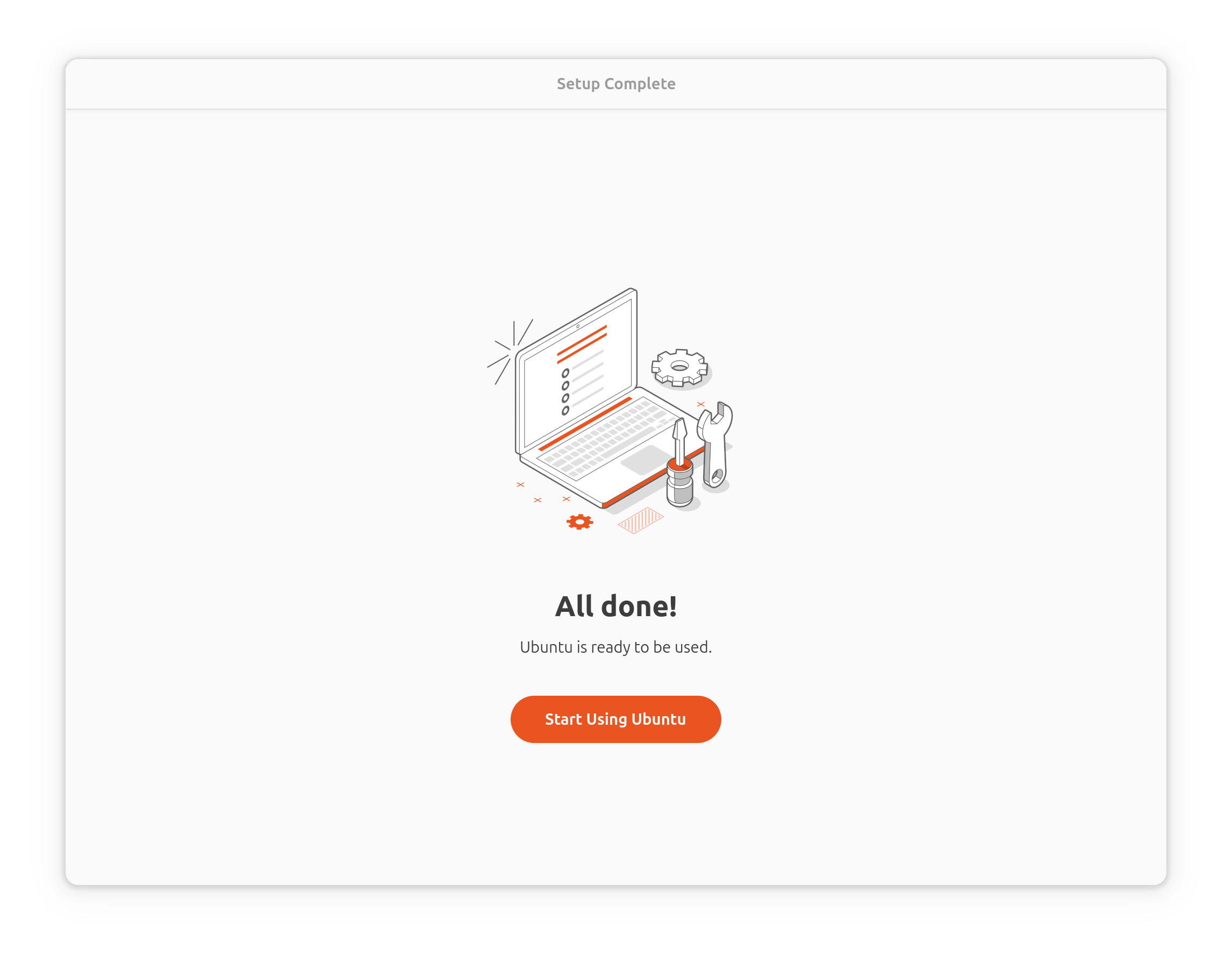
Gnome Initial Setup displays Setup Complete. Clicking Start Using Ubuntu to finish the system configuration.
Headless Mode Flow in System Configuration#
Before the target system boots for the first time, you must start a terminal program on the host computer. You can use putty, screen, or any other program that communicates through the host computer’s tty device and supports the UTF-8 character set.
Note
NVIDIA does not recommend using minicom for this application because it has some issues dealing with UTF-8.
When the target device boots for the first time after flashing and finds no display device, NVIDIA OOBE runs oem-config in headless mode. Use the following procedure to configure the target device.
Configuring the Target Device with oem-config#
oem-configdisplays a welcome screen. To advance to the next screen, press Tab and then Enter.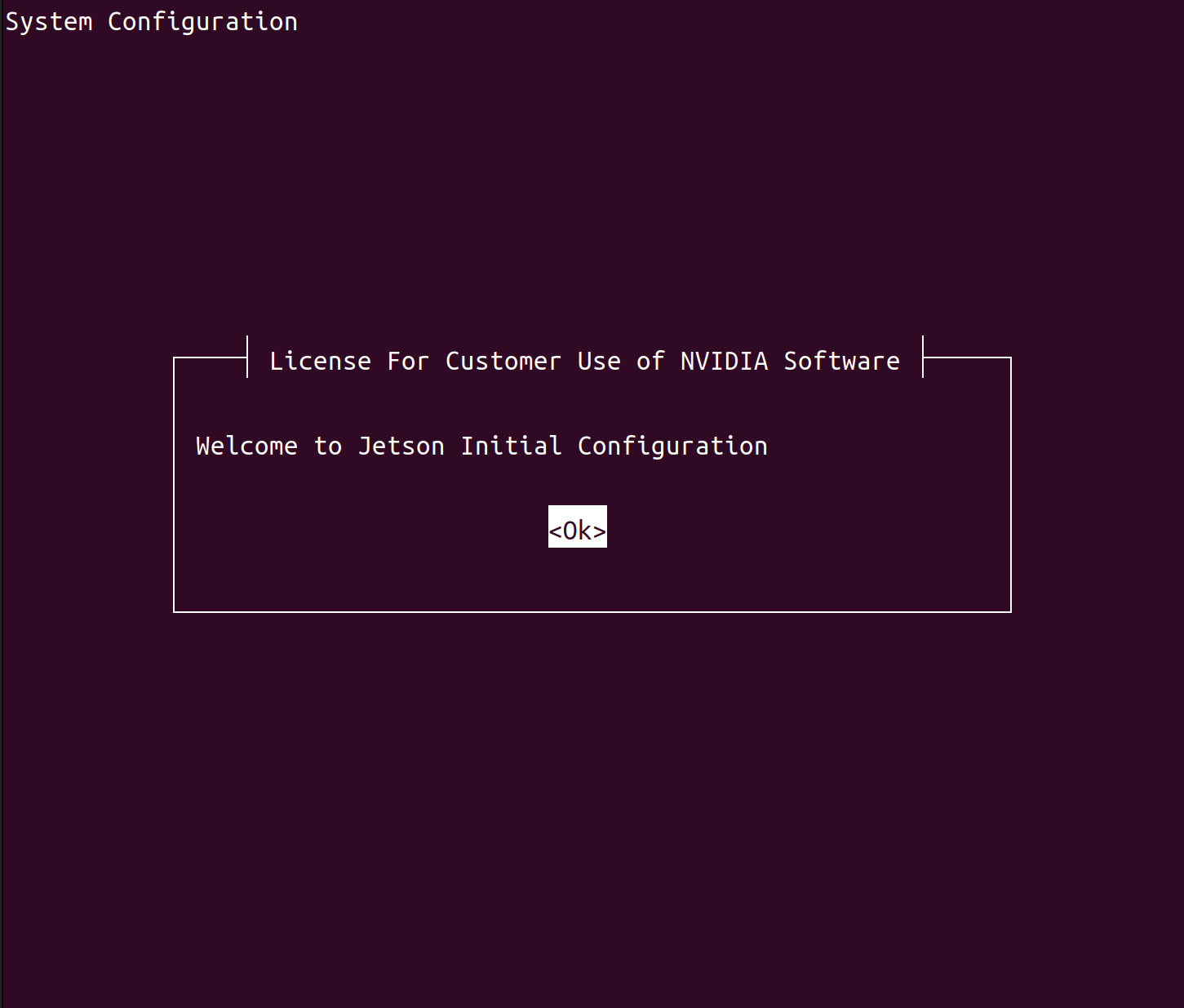
oem-configdisplays the license that governs its use. Read the license and accept it by pressing Tab and then Enter.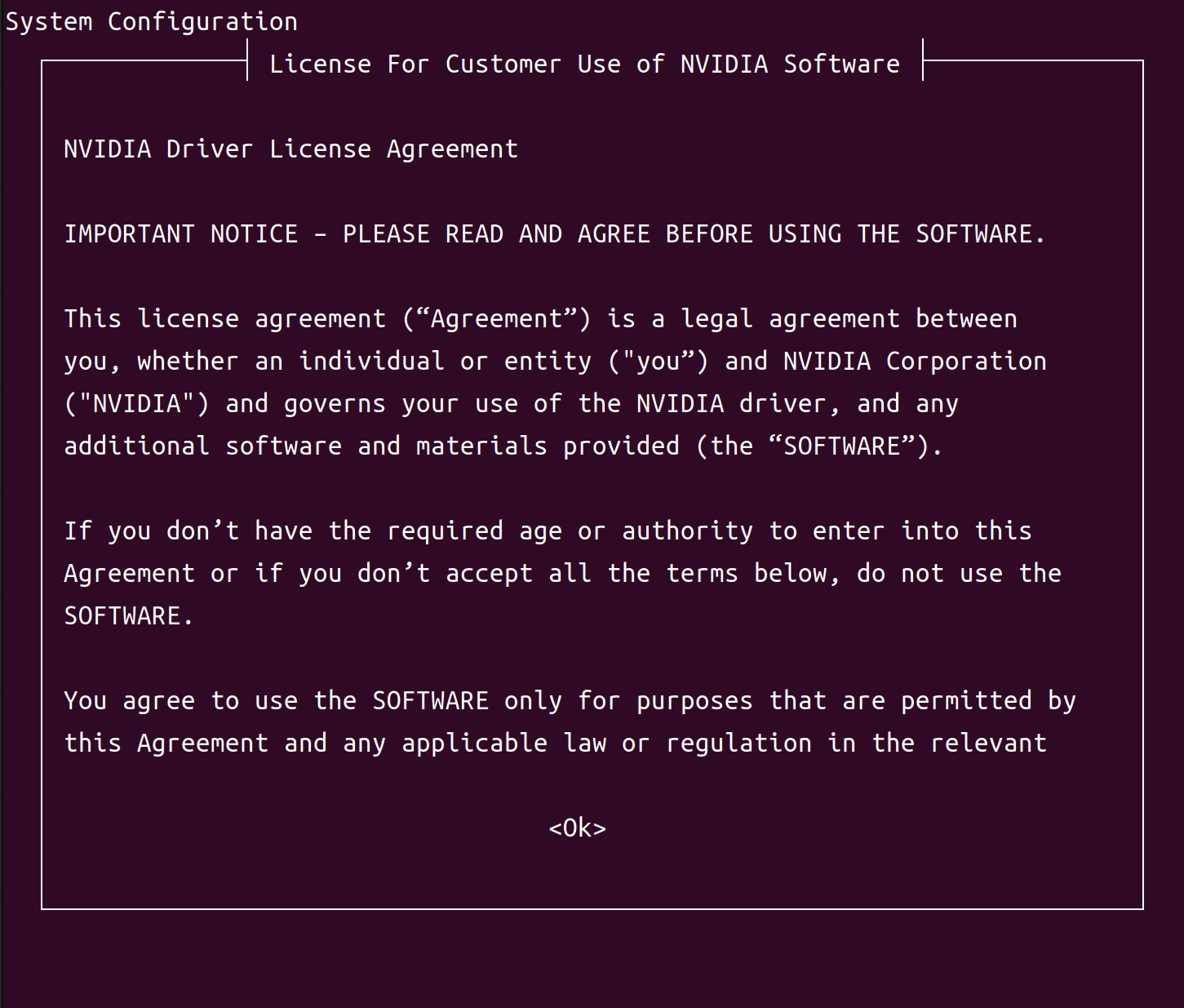
oem-configdisplays a lists of languages. Use the Up arrow and Down arrow keys to select the language you want to use for the installation process. Then press the Left arrow or Right arrow key to select OK, and press Enter.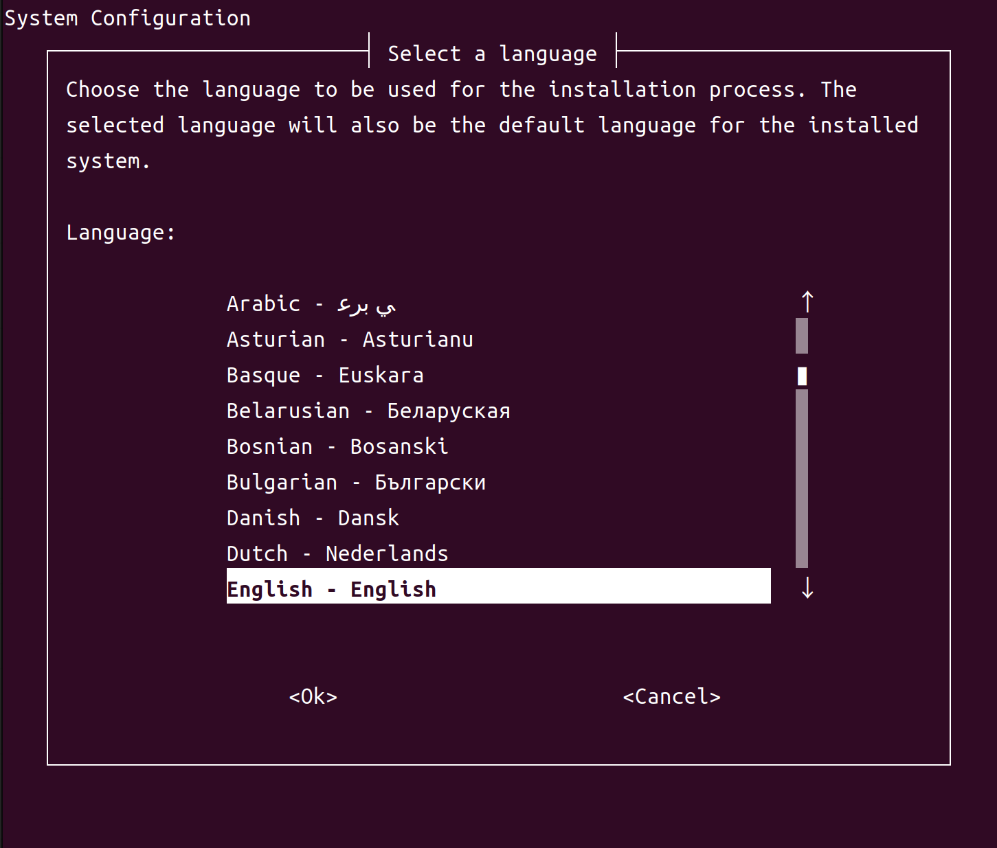
Note
To go back from any screen to the preceding one, select Cancel and press Enter. You can go back more than one screen by doing this more than once.
oem-configlists locations in which the language you selected is used. Select your location; then select OK and press Enter.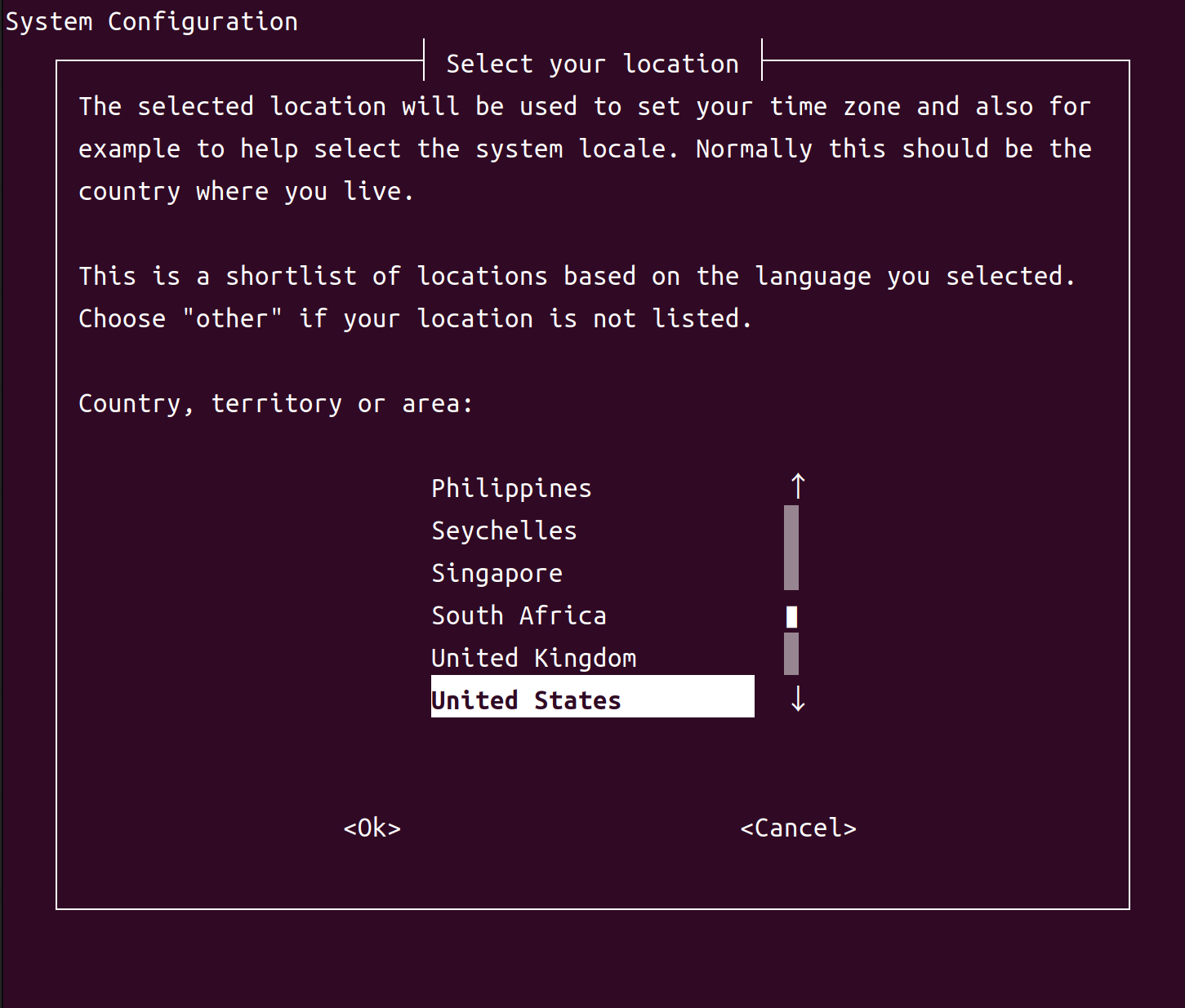
oem-configlists keyboard for various countries. Select the country of origin for your keyboard; then select OK and press Enter.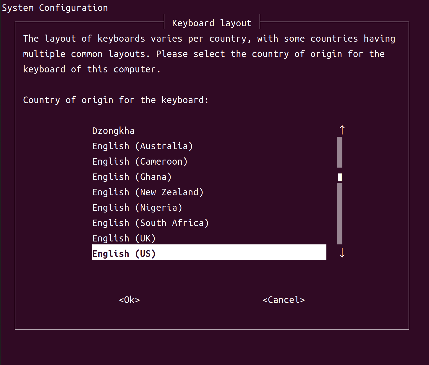
oem-configkeyboard layouts for your selected country. Select your keyboard’s layout; then select OK and press Enter.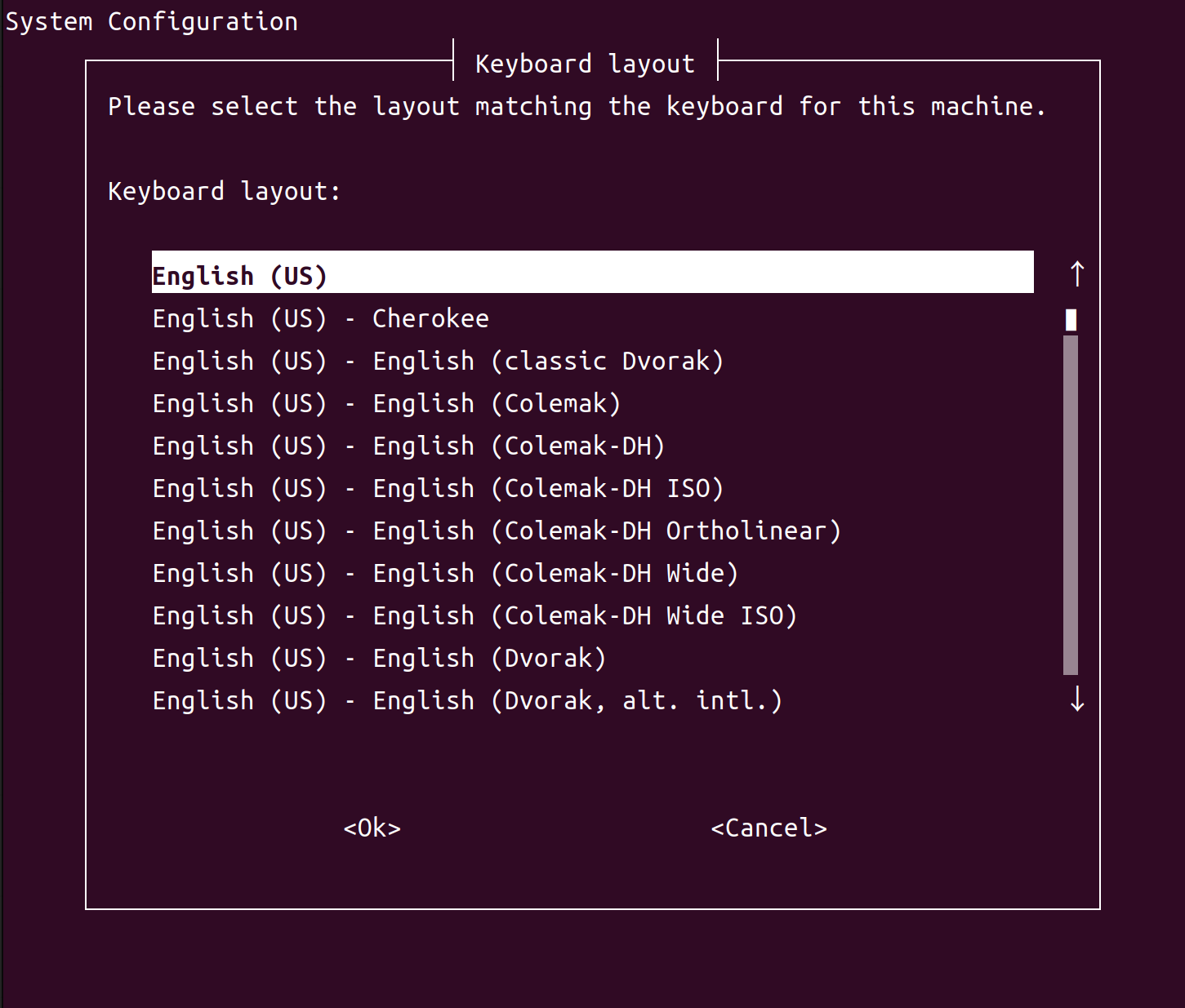
oem-configlists time zones that exist in the location you select. Select your time zone; then select OK and press Enter.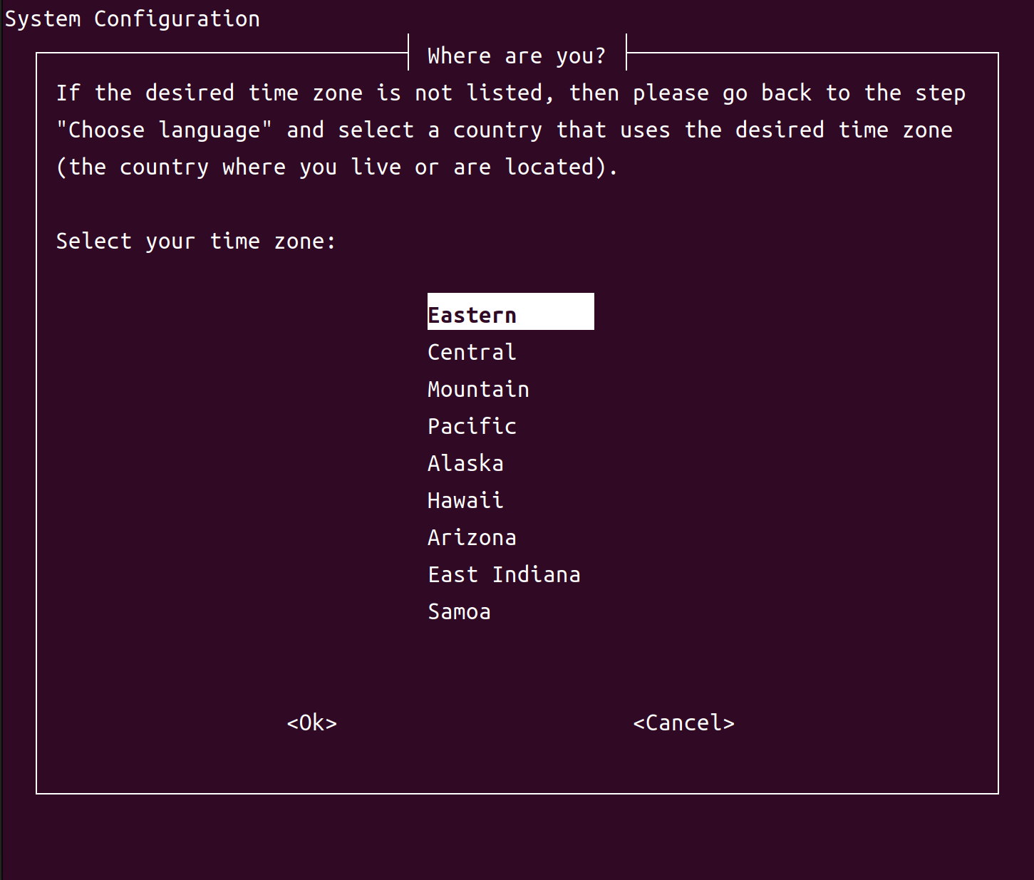
If your time zone is not listed, select Cancel as many times as necessary to go back to the screen that lists locations, and choose a different location.
oem-configasks whether you want to set the system clock to Coordinated Universal Time (UTC, or Greenwich Mean Time). Linux expects the system clock to be set to UTC, so we recommend that you select Yes and press Enter.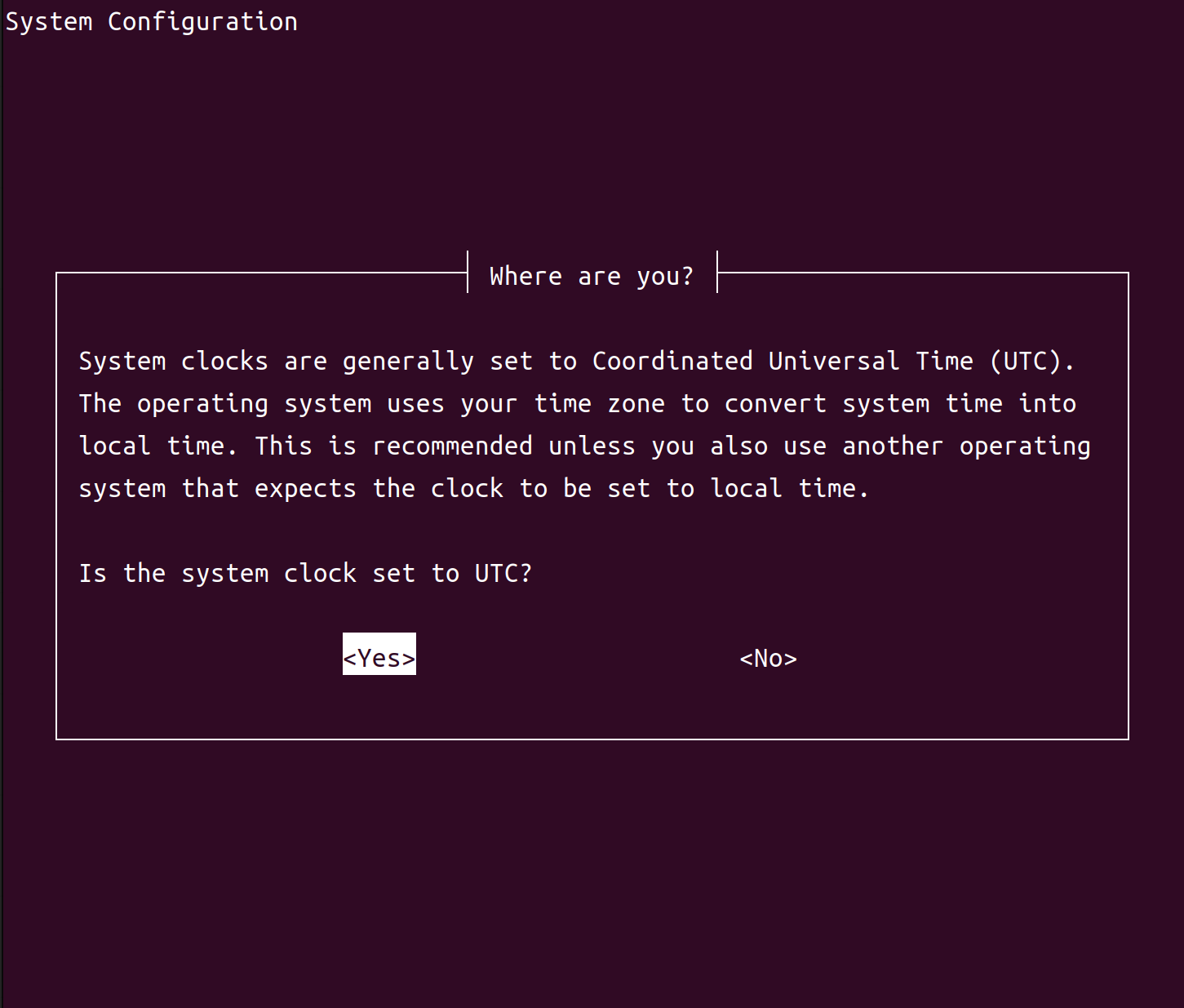
oem-configasks you to enter your name. Enter your full name (for example,John Smith), select OK, and press Enter.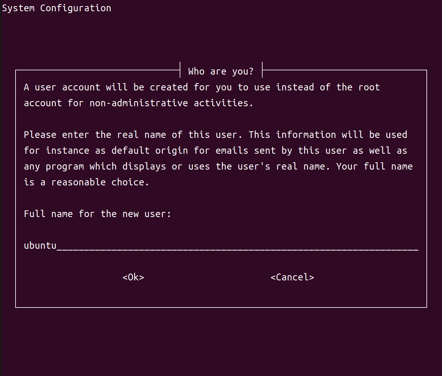
oem-configasks you to enter a username for your user account.oem-configcreates a user account with this name. Select OK and press Enter.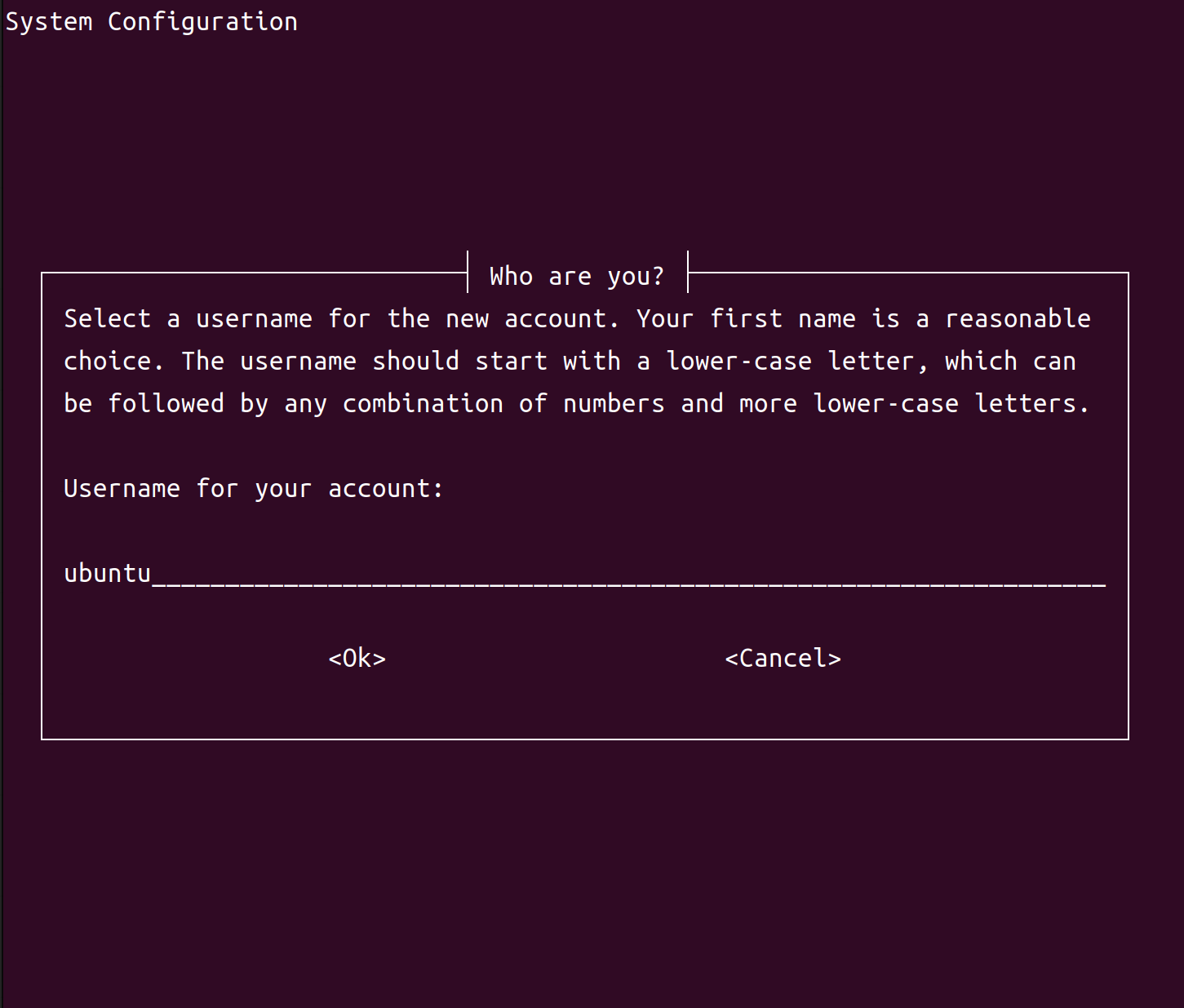
We suggest using your first name, in lowercase letters only. Use this account instead of the root account for anything other than administrative activities.
oem-configasks you to enter a password for your user account. Enter a password, select OK, and press Enter.We recommend that you choose a strong password, such as one that contains more than eight characters and at least one each of uppercase and lowercase letters, numerals, and other characters. If you enter a weak password,
oem-configasks you to confirm that you want to use it.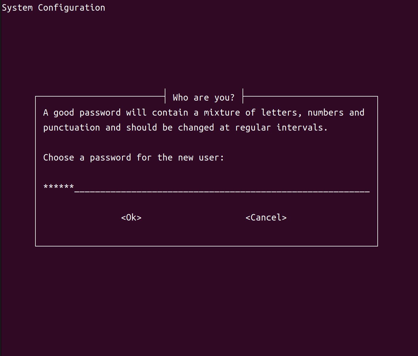
oem-configasks you to enter your password again to confirm that you entered it correctly. If you enter the same password both times, it sets the password and goes on to the next step. If not, it prompts you to enter a password again.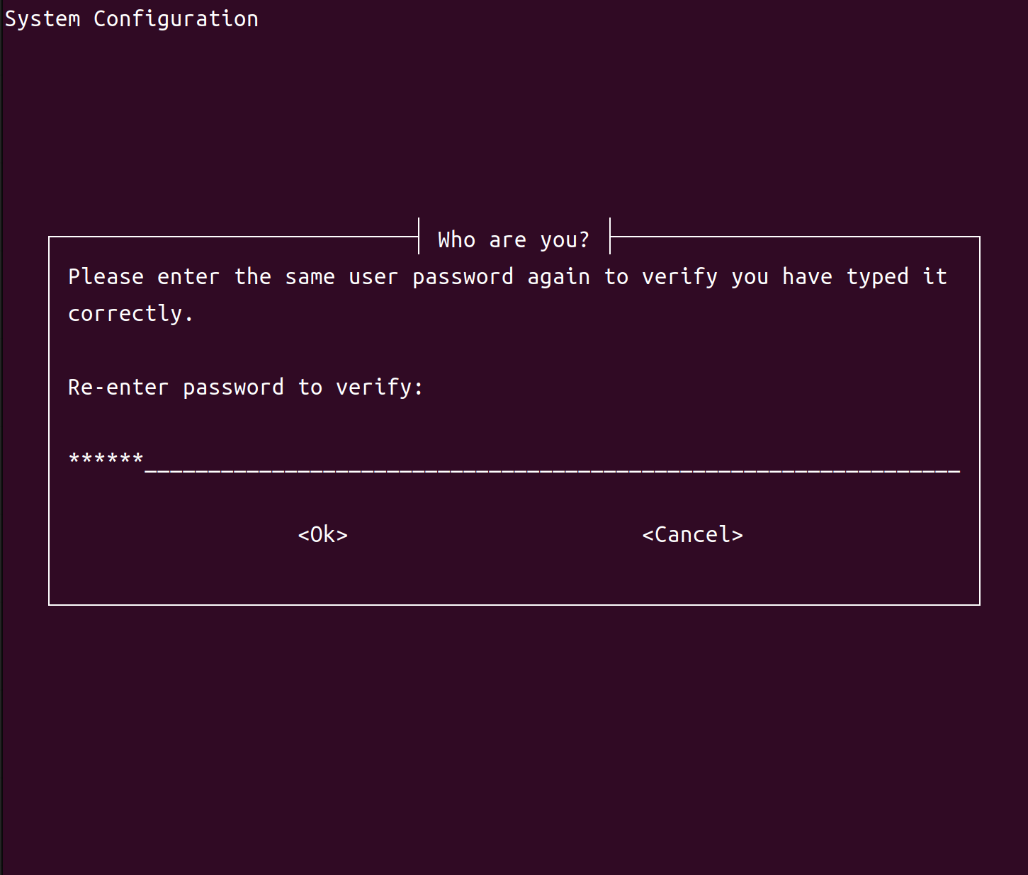
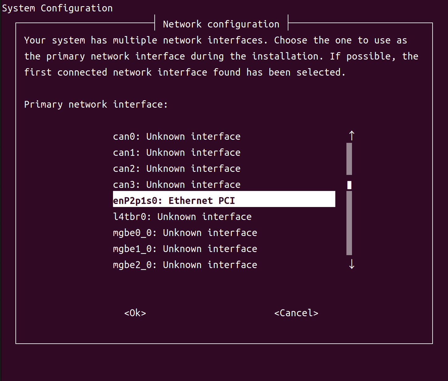
oem-configlists the interfaces that it can use as the primary network interface during installation.If you are using Ethernet as the primary network interface, make sure that the Ethernet cable is connected. Then select the eth0: Ethernet option, select OK, and press Enter.
Note
Because of a known wireless network configuration bug in
oem-config, you must either enter the SSID manually instead of selecting it from the list or wait until after initial setup is complete and then use thenmclicommand to configure wireless networking. For more details, see the ubuntu.com documentation page Configure WiFi Connections.oem-configprompts you to enter your host computer’s hostname. If you don’t know the hostname, ask your network administrator. If you are setting up a dedicated network, you can select any name. Enter the hostname, select OK, and press Enter.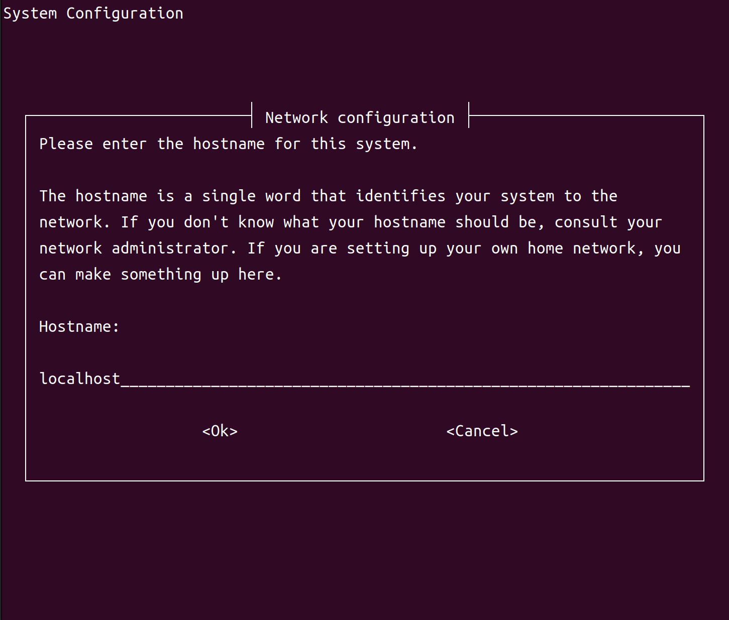
oem-configconfigures the system with the selections you have made and then proceeds to the system’s log-in prompt.
Skipping NVIDIA OOBE#
If you don’t want to run NVIDIA OOBE to set up your system, you can make the first-time boot process skip it by running the host script l4t_create_default_user.sh before you flash. The boot process runs NVIDIA OOBE if no default user is defined; l4t_create_default_user.sh creates a default user, and thus prevents NVIDIA OOBE from running.
The script’s usage is as follows:
$ l4t_create_default_user.sh [-u <user>] [-p <pswd>] [-n <host>] [-a] [-h]
This table describes the command-line options:
Command-line option |
Description |
|---|---|
-u <user> --username <user> |
Creates a default user with the specified
username. If omitted, the script creates
a default user named |
-p <pswd> --password <pswd> |
Creates the default user with the specified password. If omitted, the script generates a random password. |
-n <host> --hostname <host> |
Creates the default user with the
specified host name. If omitted, the
script uses the host name
|
-a --autologin |
Configures Jetson Linux to log in to the default user automatically when booted. If omitted, the user must log in manually. |
--accept-license |
Accepts the EULA for NVIDIA software. If omitted, the script prompts you to accept the EULA. |
-h --help |
Prints a description of the script’s usage. |
Examples#
Create a user named
nvidiawith the passwordNDZjMWM4and the host nametegra-ubuntu:$ l4t_create_default_user.sh -u nvidia -p NDZjMWM4
Create a user named
ubuntuwith a randomly generated password and the host nametegra-ubuntu, and configures Jetson Linux to log in to it automatically at boot:$ l4t_create_default_user.sh -u ubuntu -a
Create a user named
nvidiawith a randomly generated password and the host nametegra:$ l4t_create_default_user.sh -n tegra
Modifying Jetson Ramdisk#
Use the following procedure to modify the default configuration of a Jetson device’s RAM disk.
Modifying the RAM Disk#
Unpack your initrd:
$ sudo su
$ cp <initrd_file> /tmp/l4t_initrd.img
$ mkdir /tmp/temp
$ cd /tmp/temp
$ gunzip -c /tmp/l4t_initrd.img | cpio -i
Modify your initrd content in the
tmp/temp/directory according to your needs.Package your initrd:
$ sudo su
$ cd /tmp/temp
$ find . | cpio -H newc -o | gzip -9 -n > ../l4t_initrd.img
Replace the initrd with your customized initrd:
$ cp /tmp/l4t_initrd.img /boot/l4t_initrd.img
Flashing with initrd#
The initrd flash tool is the official method of flashing Jetson Thor devices with NVMe as the external storage device. You can flash it for various cases by using the following commands:
Flashing for the default case:
$ sudo ./l4t_initrd_flash.sh jetson-agx-thor-devkit external
Flashing with rootfs A/B enabled:
# Generate images for QSPI
$ sudo ROOTFS_AB=1 ./l4t_initrd_flash.sh --qspi-only --no-flash jetson-agx-thor-devkit internal

# Generate images for external storage device
$ sudo ROOTFS_AB=1 ./l4t_initrd_flash.sh --no-flash --external-device nvme0n1p1 -c ./tools/kernel_flash/flash_l4t_t264_nvme_rootfs_ab.xml --external-only --append jetson-agx-thor-devkit external

# Flash images into both storage devices
$ sudo ./l4t_initrd_flash.sh --flash-only
Flashing with disk encryption enabled:
# Generate images for QSPI
$ sudo ./l4t_initrd_flash.sh --qspi-only --no-flash jetson-agx-thor-devkit internal

# Generate images for external storage device
$ sudo ROOTFS_ENC=1 ./l4t_initrd_flash.sh --no-flash --external-device nvme0n1p1 -i ./ekb.key -c ./tools/kernel_flash/flash_l4t_t264_nvme_rootfs_enc.xml --external-only --append jetson-agx-thor-devkit external

# Flash images into both storage devices
$ sudo ./l4t_initrd_flash.sh --flash-only
Note
The “-i ./ekb.key” option specifies the disk encryption key. Refer to How to Create an Encrypted Rootfs on the Host in Disk Encryption.
Flashing with both rootfs A/B and disk encryption enabled:
# Generate images for QSPI
$ sudo ROOTFS_AB=1 ./l4t_initrd_flash.sh --qspi-only --no-flash jetson-agx-thor-devkit internal

# Generate images for external storage device
$ sudo ROOTFS_AB=1 ROOTFS_ENC=1 ./l4t_initrd_flash.sh --no-flash --external-device nvme0n1p1 -i ./ekb.key -c ./tools/kernel_flash/flash_l4t_t264_nvme_rootfs_ab_enc.xml --external-only --append jetson-agx-thor-devkit external

# Flash images into both storage devices
$ sudo ./l4t_initrd_flash.sh --flash-only
Configuring a PXE Boot Server for UEFI bootloader on Jetson#
This section assumes that users understand how to set up their network and the configuration requirements.
The UEFI bootloader on Jetson can boot from a PXE Boot Server without using a special flashing configuration.
The PXE Boot Server comprises the following components:
DHCP server: provides the IP address information and the location of the initial application (NBP).
TFTP server: hosts the NBP and other initial files (kernel, grub.cfg, initrd, and so on).
NFS server: exposes the root file system for the boot.
The DHCP should be configured to point to the NBP program. Here is a sample configuration for the isc-dhcp server. You need to modify the following configuration based on your network configuration and usage):
subnet 192.168.0.0 netmask 255.255.255.0 {
        range 192.168.0.11 192.168.0.20;
        option routers 192.168.0.1;

        # Required for PXE Boot
        class "pxeclients" {
                match if substring (option vendor-class-identifier, 0, 9) = "PXEClient";
                        filename "efi/grubnetaa64.efi.signed";
                        # TFTP Server IP address
                        next-server 192.168.0.1;
                        option root-path "/tftp/";
        }
}

host mytegra {
  hardware ethernet 48:B0:2D:B1:48:25;
  fixed-address 192.168.0.10;
}
The Kernel and initrd can be taken from the board support package directory as Image and initrd and are placed in the directory to which grub.cfg points.
For example, the following grub config pulls kernel/initrd from root of TFTP and boots from nfs location 192.168.42.1:/volume1/nfs_root:
set timeout_style=menu
set timeout=5

menuentry "Jetson" {
      linux /Image root=/dev/nfs rw netdevwait ip=:::::eth0:on nfsroot=192.168.42.1:/volume1/nfs_root fbcon=map:0 net.ifnames=0  console=ttyTCU0,115200 firmware_class.path=/etc/firmware fbcon=map:0 net.ifnames=0
      initrd /initrd
}
The TFPT server configuration using the tftpd-hpa on an Ubuntu machine:
# /etc/default/tftpd-hpa

TFTP_USERNAME="<vrlhostname>"
TFTP_DIRECTORY="/tftp"
TFTP_ADDRESS=":69"
TFTP_OPTIONS="--secure"
The kernel, the initrd, and the grub bootloader needs to be present at these locations:
/tftp/efi/grubnetaa64.efi.signed
/tftp/Image
/tftp/initrd
The NFS server /etc/exports configuration file on the NFS host with IP 192.168.42.1:
# /etc/exports
/volume1/nfs_root *(async,rw,no_root_squash,no_all_squash,no_subtree_check,insecure,anonuid=1000,anongid=1000)"
The root file system should be exported using an NFS server. After you finish configuring:
Reboot the Jetson device.
Press Esc during boot time to access the UEFI boot menu.
Select the PXEv4 boot option of the network device from which you want to boot.