

BCM Bootstrap Workflow#
This document outlines the step-by-step BCM (Base Command Manager) bootstrap process for deploying network switches in a North-South network configuration. The process follows a specific sequence to ensure proper network establishment and switch provisioning.
Bootstrap Process Overview#
The BCM bootstrap workflow follows a hierarchical approach where switches are provisioned in a specific order to establish the network infrastructure. This process ensures that each stage builds upon the previous one, creating a stable and manageable network environment.
LOM1 and BCM connectivity
LOM1 is required to bootstrap all Ethernet switches. The BCM uses a 1G LOM1 port toward the Access-OOB switch for provisioning.
If the BCM does not have the LOM1 1G port connected to the Access-OOB switch, a high-speed data port must be up first. Additional manual configuration is required when LOM1 is not available.
The BCM has bond0 for InBand and bond1 for OOB; all Ethernet switches are part of the VRFs associated with these bonds.
The following diagram shows the OOB management and bootstrap connectivity between the BCM headnodes and the Access-OOB switch (LOM and BMC connections). Copy the generated startup.yaml file from the Access-OOB switch configuration to the switch as part of the bootstrap workflow.
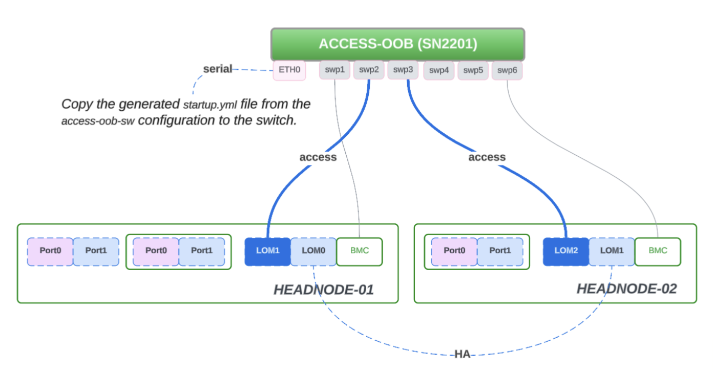
Figure 8 Bootstrap OOB topology: Access-OOB switch to headnodes (LOM1 access, LOM0/LOM2, BMC). Copy the generated startup.yaml from the Access-OOB configuration to the switch.#
How to work through this topic
Confirm LOM1 and Access-OOB connectivity using the OOB topology figure preceding this subsection.
Keep the bootstrap sequence figure open while you work; confirm each stage in BCM (or your validation checklist) before you continue to the next.
Open Bootstrap Stages next and follow the numbered steps in order when you need actions, inputs, checkpoints, and switch-level notes.
Bootstrap Stages#
There are eight steps to run during the BCM bootstrap process.
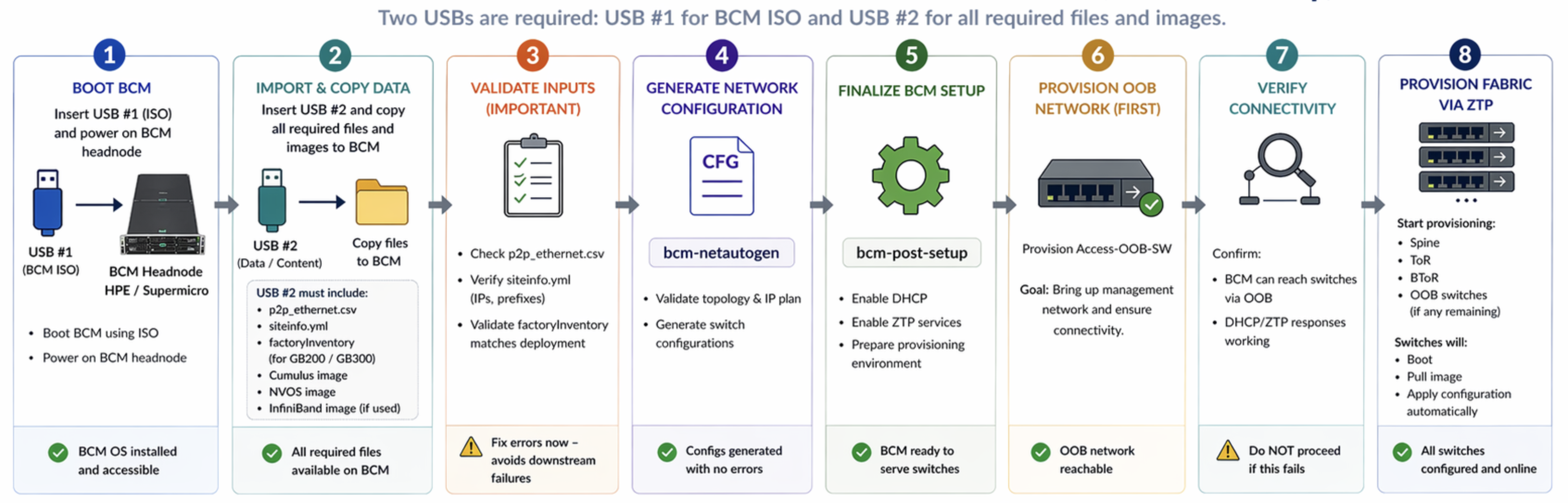
Figure 9 BCM bootstrap sequence—follow these stages in order, then use the step-by-step Bootstrap Stages section for actions, inputs, checkpoints, and switch provisioning notes.#
Step 1 — Boot BCM#
Action: Boot the BCM headnode from the BCM installation ISO, then work through the BCM Wizard to the end of first-boot setup.
During the wizard, use the subnets and IP addresses that already match your validated network plan—do not invent new ranges at install time. Typical sources for those values are:
A pre-run from the Network Dashboard UI (internal NVIDIA tooling) that produced the prefixes and host addressing you intend to deploy, or
The same values after you validated them locally (for example using Docker-based tooling or containers that exercised your planned inputs before you image the headnode).
Key inputs: USB #1 (BCM ISO); subnet and IP plan from Network Dashboard pre-run or local validation.
Output: BCM system installed and running; wizard completed with addressing aligned to your plan.
Checkpoint: BCM is reachable (management access works as expected for your environment), and wizard-entered networking matches the pre-run or locally validated data you will reuse in later steps.
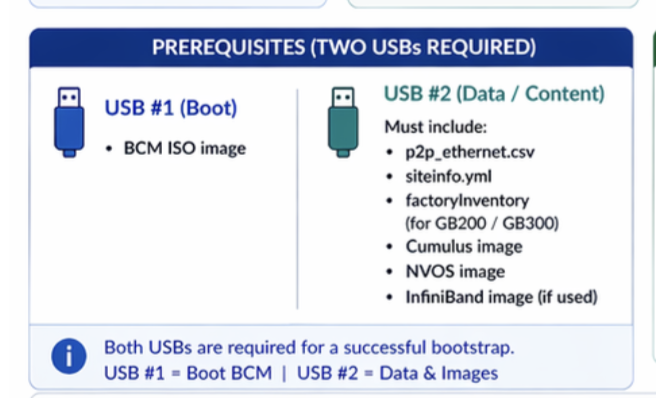
Figure 10 USB #1 carries the BCM installation ISO; USB #2 carries configurations, switch images, and related files for steps 1 and 2.#
Step 2 — Import and copy data#
Action: Insert USB #2 and copy all required files onto the BCM headnode.
Key inputs: USB #2 (configuration payloads, switch images, and any other artifacts your runbook lists).
Output: Files are present on BCM at the paths your next commands expect.
Checkpoint: Inventory the mount or copy log and confirm all required files are present before you validate inputs.
Mount the USB device
The USB partition device (for example /dev/sdb1) differs by headnode and port. Use sudo fdisk -l and lsblk to pick the correct VFAT partition before you mount.
sudo fdisk -l
sudo mkdir -p /media/CUMULUS
sudo mount -t vfat /dev/sdb1 /media/CUMULUS
lsblk
Copy files into BCM paths
sudo rsync -av /media/CUMULUS/*.bin /cm/local/apps/cmd/etc/htdocs/switch/image
sudo rsync -av /media/CUMULUS/*.csv /cm/local/apps/bcm-superpod-network/config/
Add more rsync lines if your USB carries other extensions (for example siteinfo.yml) or paths your release expects.
Step 3 — Validate inputs#
Action: Verify topology, IP plans, and inventory against your design.
Key inputs: following files:
p2p_ethernet.csvsiteinfo.ymlrack_<rackName>.csv— per-rack export for GB200/GB300, renamed to match the rack key underrack_mappinginsiteinfo(for examplerack_A08.csv; see Factory inventory (GB200 / GB300) in step 3).
Output: Clean, validated inputs (no blocking errors from your validation tooling or checklist).
Checkpoint: No validation errors; fix data issues before you run config generation.
Factory inventory (GB200 / GB300)
Prerequisite: Rename the rack inventory export before validation or bcm-netautogen so the filename matches what automation expects for that rack.
The rackName in the renamed file must match the rack key under rack_mapping in siteinfo.yml (or siteinfo.yaml). For example, if siteinfo.yml contains rack_mapping: with key A08, the inventory file for that rack must be named rack_A08.csv.
mv <rack_inventory_file.csv> rack_<rackName>.csv
Replace <rack_inventory_file.csv> with your exported CSV path and <rackName> with the same rack identifier as in rack_mapping (omit angle brackets in the real command).
Step 4 — Generate config#
Action: Run bcm-netautogen to build switch configurations from the validated files.
Key inputs: Validated input files from step 3.
To run bcm-netautogen
Load the BCM SuperPOD network module environment (exact module name can vary by BCM install layout):
module load bcm-superpod-network
Run
bcm-netautogenwith--config-pathset to the directory that contains your inputs together: rack inventory CSVs (rack_<rackName>.csv),siteinfo.yml/siteinfo.yaml, andp2p_ethernet.csv(names may match your layout).bcm-netautogen --config-path <path-to-directory-with-inputs> -l netauto.log
Replace
<path-to-directory-with-inputs>with the real path (for example a per-site folder you copied from USB in step 2).
Example
The following example adds BMC, switch, and NVOS password flags, enables verbose logging, and writes the log under logs/. Substitute your own paths, passwords, and log location; do not store real passwords in shared documentation or source control.
bcm-netautogen --config-path files/B300_S1/ \
  --server-bmc-password '<password>' \
  --switch-password '<password>' \
  --nvos-password '<password>' \
  -l logs/netauto.log \
  -v
Generated output location
After a successful run, generated configuration and supporting data are written under /cm/local/apps/bcm-superpod-network/config/. Review that directory together with the log file you passed to -l before you move to step 5.
Summary (example output)
The following output shows a representative summary from bcm-netautogen (exact fields and layout can vary by BCM release).
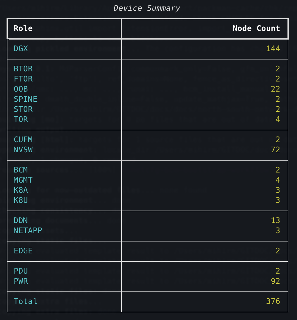
Figure 11 Example summary output from bcm-netautogen.#
Network allocation (example output)
The following output shows a representative network allocation view (prefixes, segments, or assignments as produced by the tool).
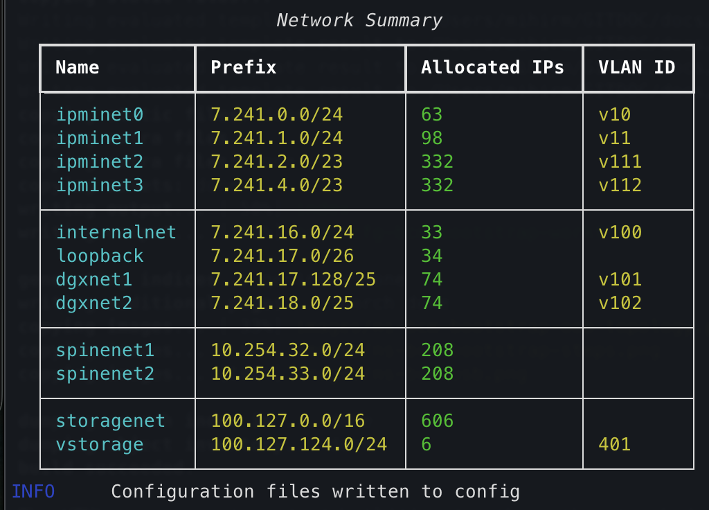
Figure 12 Example network allocation output from bcm-netautogen.#
Review generated config and IP allocation
Under /cm/local/apps/bcm-superpod-network/config/, inspect the main artifacts below together with the summary and network allocation figures preceding this subsection.
Summarized file |
Description |
|---|---|
|
Per-device JSON exports kept for reference only (not part of the standard operational upload path). |
|
Import path when using the cmsh list workflow. |
|
Readme-style reference for viewing IP allocations per device. |
|
Primary payload used to upload and configure BCM components. |
|
Inventory used to push configuration with Ansible (NVIDIA Air flow). |
|
Generated Graphviz |
|
Run first only if you use the optional JSON import path (see the note following this table). |
|
Run second only in that same optional JSON import sequence. |
Per-hostname folders (for example |
One directory per switch hostname; each contains |
Note
The bcm_js/ directory is generated for reference (inspection, diffs, or support). Do not rely on it for the normal BCM bootstrap: use network-configuration.yml, the per-hostname startup.yaml trees, ip-allocation.md, and the documented cmsh / ZTP flows instead of uploading individual JSON files from bcm_js/.
Step 5 — Importing Objects into BCM#
Action: Run bcm-pod-setup so BCM ingests the artifacts from step 4 and prepares the pod environment for DHCP, ZTP, and downstream automation.
Key inputs: Output from bcm-netautogen under /cm/local/apps/bcm-superpod-network/config/, especially network-configuration.yml (and the rest of the generated tree described in step 4).
bcm-pod-setup executes a fixed set of internal phases, though the exact names may differ by BCM release. Use the following figure, commands, and table to interpret logs and support bundles, and to verify each phase on your build.
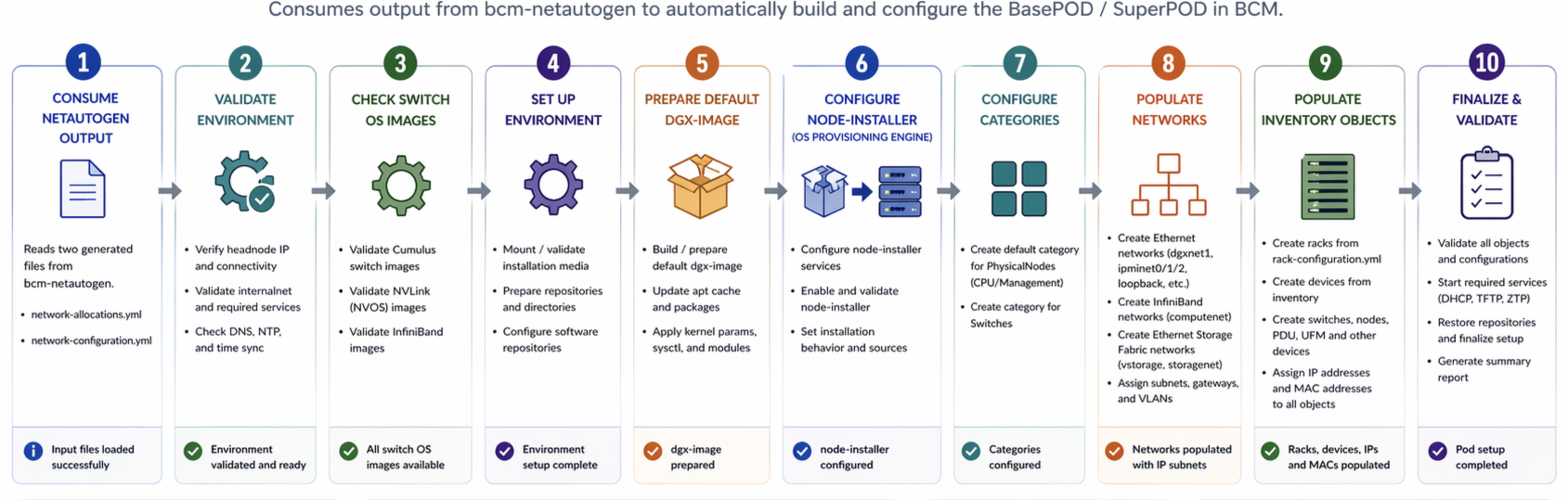
Figure 13 Typical bcm-pod-setup stage flow (cross-check with the table following the commands in this section).#
To run bcm-pod-setup
Load the post-install environment on the BCM headnode.
module load bcm-post-install
Run
bcm-pod-setupwith the OS ISO and-C/-Sprefixes from your design:-Iis the DGX/BCM install image,-Cis the control (or in-band) fabric range,-Sis storage. Adjust the values to the prefixes you validated in step 1 and your Network Dashboard pre-runs.bcm-pod-setup \ -I /root/bcm-<image>.iso \ -C 100.126.0.0/16 \ -S 100.127.0.0/16
Optional flags (only when your runbook allows them): a single run can add
--dgx-image,--debug,--skip-bcm-ip-check, and--import-only(import-only path).One invocation, with the optional flags on separate lines for readability:
bcm-pod-setup \
  -I /root/automated-bcm.iso \
  -C 100.126.0.0/16 \
  -S 100.127.0.0/16 \
  --dgx-image dgx-image \
  --debug \
  --skip-bcm-ip-check \
  --import-only
Warning
bond0 (In-Band) and bond1 (OOB) are not created by bcm-pod-setup.
After import, set the real interface names in cmsh (for example renameLOM1 in step 6), then apply bond0 / bond1 to match the overview and your runbook.
Example: To create bonded interfaces (In-Band) in cmsh, follow these steps:
Replace <NIC1>, <NIC2>, and <IP> with your design.
Select the first member port, clear any address, and commit (frees the NICs before you bond them):
cmsh -c "device; use master; interfaces; use <NIC1>; clear ip; commit"
Create
bond0with network, IP, LACP mode, bond options, and memberNICs, then run commit, show, and a final commit (see the second command):cmsh -c "device; use master; interfaces; add bond bond0; use bond0; set network internalnet; set ip <IP>; set mode 4; set options \"bond-miimon=100 bond-primary=<NIC1>\"; set interfaces <NIC1>,<NIC2>; commit; show; commit"
Step |
Stage |
What it does |
|---|---|---|
1 |
Load generated pod data |
Reads |
2 |
Validate environment |
Checks headnode IP and internal network readiness. |
3 |
Verify switch images |
Confirms Cumulus Linux, NVOS, and InfiniBand images are available where BCM expects them. |
4 |
Set up environment |
Prepares repositories, media, and the runtime environment for provisioning. |
5 |
Prepare default image |
Builds or prepares the default |
6 |
Configure node-installer |
Sets up node-installer services and behavior. |
7 |
Configure categories |
Creates categories for PhysicalNodes and Switches. |
8 |
Populate networks |
Creates Ethernet, InfiniBand, storage, and loopback networks. |
9 |
Populate inventory objects |
Creates racks, devices, switches, and assigns IP and MAC data. |
10 |
Configure infrastructure objects |
Applies switch, node, and related object configuration. |
11 |
Finalize |
Cleans up, restores repository state, and completes deployment. |
Note
Cumulus and NVOS are x86 - If BCM running ARM64 If BCM is running on ARCH: ARM64, an additional AMD image <NAME>_x86.iso must be mounted. This ISO is required to retrieve the cm-lite-daemon package, which is necessary for installation on Cumulus and NVOS systems.
Steps:
# Upload bcm_x86.iso on to BCM
$ mount -o loop <file_name_bcm_x86.iso> /mnt/dvd/
$ cd /mnt/dvd/data
$ cm-lite-daemon-repo /mnt/dvd/

# File will be copied over here:
$ ls -l /cm/local/apps/cmd/etc/htdocs/switch/ | grep cm-lite
Step 6 — Provision OOB#
Action: Bring up the Access-OOB switch (primary OOB) using the generated startup.yaml, then attach BCM management on LOM1 toward that switch and install cm-lite-daemon on the Access-OOB switch.
Key inputs: startup.yaml of the Access-OOB switch from /cm/local/apps/bcm-superpod-network/config/ after bcm-netautogen (and bcm-pod-setup when your runbook requires it).
Set up the Access-OOB switch#
The Access-OOB switch is typically an SN2201. It is the first OOB switch you bring into service so that core Ethernet switch management paths can land on a stable OOB fabric.
Bring up the Access-OOB switch (recommended path)
After bcm-netautogen completes, open the generated tree under /cm/local/apps/bcm-superpod-network/config/ and locate startup.yaml for the Access-OOB switch—usually under a folder named for that switch hostname (for example .../config/<access-oob-hostname>/startup.yaml).
Upload startup.yaml over the serial console (recommended when you have no in-band path yet). You need a USB-C to RJ45 adapter to the switch console port.
Example: A session from a macOS laptop (replace the TTY device with the one your USB serial adapter creates, for example from ls /dev/cu.*):
screen /dev/cu.usb 115200
Apply NVUE configuration on the Access-OOB switch
echo -n > /etc/nvue.d/startup.yaml
vi /etc/nvue.d/startup.yaml
# Paste the contents of startup.yaml from the BCM headnode, save, and exit.
nv config replace /etc/nvue.d/startup.yaml
nv config apply -y
Confirm the Access-OOB switch is operational from the fabric perspective (ports up, management VLAN or OOB interfaces as designed) before you continue on the BCM headnode.
Configure BCM toward the Access-OOB switch
Log in to the BCM headnode then, run cmsh.
Rename the physical NIC that faces the Access-OOB switch to
renameLOM1in BCM. Do not renameETH0; only the LOM1-facing link should userenameLOM1so the documented bootstrap path stays consistent.Bind ``renameLOM1`` to the correct host interface (the actual LOM1 device name on the headnode):
cmsh -c "device; use master; interfaces; use renameLOM1; set networkdevicename <LOM1_NIC_NAME>; commit"
Replace
<LOM1_NIC_NAME>with the Linux network device name (for example theeno/ethstyle name shown byip link).
Then create bond0 (In-Band) with the cmsh one-liner (Example: create `bond0` in cmsh, after the Warning and before the bcm-pod-setup internal phases table) once the member ports match your design.
Install cm-lite-daemon on the Access-OOB switch
cm-lite-daemon is not always present by default—install it from cmsh when your BCM release requires it:
cmsh; device;
litedaemon download
litedaemon install <AccessOOB_switch_hostname>
Use the same hostname BCM uses for the Access-OOB SN2201 in place of <AccessOOB_switch_hostname>.
Important
The Access-OOB switch does not use a normal physical eth0 path for this bootstrap pattern; a loopback address is used so cm-lite-daemon can be installed cleanly. Follow the addressing in the generated startup.yaml and your BCM release notes—do not assume eth0 must be up for the daemon install.
Step 7 — Verify connectivity#
Action: Confirm that the OOB path from the headnode to the Access-OOB switch is usable, that cm-lite-daemon is in place, and that switch identity data (MACs) is captured for BCM before you widen ZTP.
Key inputs: Working OOB network and Access-OOB configuration from step 6; switch inventory access for MAC collection.
Connectivity checklist
Treat each ☐ as “yes / not yet.” Finish the first two before you rely on ARP-based MAC discovery.
☐ |
1G OOB to Access-OOB — The headnode can reach the Access-OOB management IP on the 1G path (LOM/ |
☐ |
|
☐ |
All switch MACs in BCM — Each switch object in BCM has the correct MAC (use auto discover when the following subsection allows it; otherwise set MAC**s **manually and verify). |
Automatic MAC discovery (BCM)
You can have BCM discover and populate switch MACs from the switchport and ARP data it sees over OOB, when all of the following are true:
The Access-OOB switch is configured in BCM and active (OOB is up in BCM, not just pingable on the wire).
Action |
Command or flow |
Purpose |
|---|---|---|
Auto: discover MAC in BCM |
UI: Auto Discover MAC; or in |
Pulls the ``mac`` from OOB/ARP when Access-OOB is in BCM, |
Manual: set MAC in BCM |
|
Sets a MAC when the auto path is not used or has not run for that device. |
Verify |
|
Confirms the ``mac`` stored for each ``Switch`` after import or a manual set. |
Step 8 — Provision fabric#
Action: Start ZTP (or the equivalent zero-touch workflow) so remaining switches pull images and configs in the supported order.
Key inputs: Images and generated configs from earlier steps; stable OOB from steps 6–7.
Output: Data-plane and fabric switches move to an operational, managed state.
Checkpoint: All switches are online and reported healthy in BCM (or your NMS), matching the topology you validated in step 3.
Important
Switch provisioning order: With Access-OOB up (step 6), provision the rest in order: secondary OOB (if any) → OOB spine (if present) → fabric SPINE → TOR last (confirm against your runbook). BCM manages over LOM1 / Access-OOB—it is not a fabric tier.
Action |
Command |
Purpose |
|---|---|---|
Reset or reinstall the OS |
sudo onie-select -i -y then sudo reboot (on the switch shell, as a user with sudo) |
Reinstalls or moves to a new Cumulus-compatible image with ONIE, then reboots so the switch can re-enter ZTP. |
Factory default |
sudo onie-select -k -y then sudo reboot (on the switch shell, as a user with sudo) |
NOS to factory; next boot re-enables a clean ZTP and DHCP pass. |
Troubleshooting BCM Bootstrap Issues#
Common issues and solutions during the BCM bootstrap process. The switch provisioning subsections (primary OOB through TOR) align with steps 6–8 when you work on Access-OOB, reachability, and ZTP.
Switch provisioning — primary OOB (Access-OOB) issues:
BCM cannot reach Access OOB switch: Check physical cabling and IP configuration
Access OOB switch not booting: Verify power supply and firmware
Switch provisioning — remaining OOB issues:
Secondary OOB switches not discovered: Check ETH0 connections to Access OOB
Provisioning failures: Verify BCM configuration and network settings
Switch provisioning — SPINE issues:
SPINE switches not configuring: Check SPINE switch connections and BCM discovery
Core network not establishing: Verify SPINE switch configuration and routing
Switch provisioning — TOR issues:
TOR switches not configuring: Check TOR switch connections and BCM discovery
Rack connectivity issues: Verify TOR switch configuration and VLAN settings