

Input File Format Requirements (Manifest)#
The bcm-superpod-network (netautogen) stage consumes a fixed set of inputs: point-to-point Ethernet cabling (p2p_ethernet.csv), site parameters (siteinfo.yml / siteinfo.yaml), and factory rack inventory (CSV). This topic summarizes format requirements for each file, including column layouts, worksheet naming, naming conventions, and extended examples.
This topic is organized into the following sections:
Point-to-Point (P2P) format#
Top · Point-to-Point (P2P) format · SiteInfo format · Factory inventory · NetworkDash UI
This section outlines the structure and meaning of each column within the Point-to-Point cabling file utilized by netautogen. This file is critical for accurately defining the interconnections between systems within a rack and across the data center topology. You can use one of the following formatting options:
Manual: You may convert manually the Excel file to a .csv file. * This is a time consuming process. Gather all the ethernet connections from each sheet in the Excel and consolidate them into a single .csv file.
Automated: You can use the Networkdash UI tool (Networkdash UI) for internal NVIDIA teams to format the Excel file.
Workbook Preparation
Add a Validate-columns sheet
Add a sheet named
Validate-columnsthat contains only column headers (no data rows). The sheet defines the column format that the tool compares headers against other sheets. Use a two-row header layout with Source and Dest group labels, as in the following figure.A starter Validate-columns workbook template is available in Google Sheets: Validate-columns template.
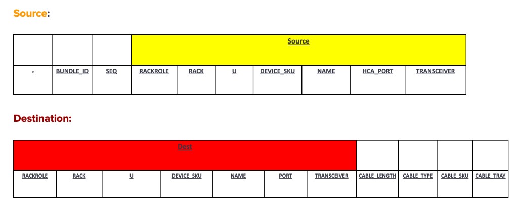
The first data columns are
BUNDLE_IDandSEQ. The columns grouped under Source areRACKROLE,RACK,U,DEVICE_SKU,NAME,HCA_PORT, andTRANSCEIVER. The columns grouped under Dest areRACKROLE,RACK,U,DEVICE_SKU,NAME,PORT, andTRANSCEIVER, followed by cable fieldsCABLE_LENGTH,CABLE_TYPE,CABLE_SKU, andCABLE_TRAY. Some tools or exports use a single header row withSOURCE_/DEST_prefixes to distinguish repeated names; align your workbook with whichever format your process requires.Name each sheet you want to combine
Assign each connection sheet that you want the tool to merge a tab name that starts with the correct traffic-type prefix:
(ETH)-: Ethernet(IB)-: InfiniBandS(n): logical scalable unit grouping (for example,S(1)throughS(n)).<Flow>: traffic or connection type.
Table 7 Examples of Worksheet Tab Names# Tab name
Description
(ETH)-S1-DGX-DATA(ETH)-S1-DGX-OOB(ETH)-S1-DGX-HSS(ETH)-HSS-UPLINKEthernet scalable unit
S(1)throughS(n)point-to-point between DGX and TOR.(ETH)-S1-SW-UPLINK(ETH)-S1-SW-EDGEEthernet from switch to spines; connections to edge devices.
(ETH)-S1-NODE-OOB(ETH)-S1-NODE-DATAEthernet out-of-band from the node, including SW-to-OOB, Node-to-OOB, and DGX-to-OOB.
(IB)-S1-DGX-IBInfiniBand from DGX to compute IB.
(IB)-S1-CLEAF-CSPINECompute leaf to spine uplinks.
Validate_Columns
Just provide column format to compare with other tabs. This column is (Required).
Other reference sheets (as needed for your project):
NAME_MAPPING — Maps customer naming to the default naming scheme when the tool combines sheets.
Physical Port Assignment
On the P2P sheets, PhysicalPort and SourceBreakOut / DestBreakOut tell netautogen how each row maps to real switch hardware and breakout mode. Values must match how ports are labeled on the switch (parent port, cage, and cable index) and where breakouts are allowed.
Use a single three-part pattern for the switch side of the connection:
<parentport> / <switchport cage> / <# of cables>parentport — Logical parent port index on the switch (the port group you are using).
switchport cage — Cage or connector group for that port on the switch faceplate.
# of cables — Which cable in that path when more than one physical cable maps to the same parent/cage context (often
1for a single cable).
Note
Example: (PhysicalPort)
1 / 1 / 1means parent port1, cage1, first cable in that mapping. Fill all three parts consistently with your site’s port labeling; do not mix in free text or omit segments unless your tooling explicitly allows it.SourceBreakOut and DestBreakOut
These fields describe how a high-speed parent port is split (breakout), when the switch supports it:
2x— 2 × 400G4x— 4 × 200G8x— 8 × 100G
Table 8 Breakout Rules# Rule
Correct
Incorrect
Example error message (invalid data)
Where to assign breakout (
2x,4x,8x)On each parent port that ends with ``s0`` only (for example
1s0with4x,2s0with4x,3s0with4x).On sub-ports after breakout:
1s1,1s2,1s3, or any port that is not ans0parent (for example1s1with4x,1s2with4x).Breakout '4x' is not allowed on sub-port '1s1'; assign breakout modes only on parent ports ending with 's0' (for example '1s0').PhysicalPort vs SourceBreakOut / DestBreakOut
PhysicalPort uses only the three-part path (for example
1 / 1 / 1). Put2x/4x/8xin SourceBreakOut or DestBreakOut.Putting breakout text (such as
4x) in PhysicalPort, or leaving PhysicalPort blank while only filling breakout fields.Column PhysicalPort must match 'parent/cage/cable'; breakout value '4x' belongs in SourceBreakOut or DestBreakOut.If a port is not broken out, leave SourceBreakOut / DestBreakOut empty or follow the template your NVIS or automation workflow specifies for non-breakout links.
Note
The P2P file should include all columns above, with each row representing a single point-to-point connection. Keeping the source and destination columns grouped together in a single table improves readability and makes the file easier to work with for both humans and automation tools.
Connection Flow#
This section provides an example of the connection type.
Note
The term “Flow” is used in this context to refer to the type or direction of network connection between devices or components in the system. A more precise term is “Connection Type,” as it describes the nature and endpoints of each network link (e.g., NODE-OOB, DGX-DATA). For a formal definition, see Flow in the Glossary of Terms.
FLOW Name |
Meaning |
|---|---|
NODE-OOB |
Connection from compute node to OOB switch (out-of-band management). |
NODE-DATA |
Compute nodes to data (IB or Ethernet) fabric. |
DGX-OOB |
DGX system to out-of-band switch. |
DGX-DATA |
DGX system to data switch or network fabric. |
NODE-NODE |
Direct connection between compute nodes. |
SW-OOB |
Out-of-band cabling between switches. |
SW-UPLINK |
Uplink from switch to aggregation or spine switch. |
STORAGE-DATA |
Storage (HSS) or (NFS) system connected to a data switch or host. |
STORAGE-OOB |
Storage system to out-of-band switch. |
UFM-OOB |
UFM system (fabric manager) out-of-band connection. |
UFM-DATA |
UFM system connected to a data network. |
EDGE-SW |
Edge switch connections (e.g., border leaf or service leaf). |
DGX-OOB |
In-rack cabling from DGX to OOB switch. |
DGX-DATA |
In-rack cabling from DGX to leaf/data switch. |
NVSW-OOB |
In-rack NVLink Switch to OOB cabling. |
PWR-OOB |
PWR and PDU to OOB cabling. |
ACCESS-OOB |
First OOB Switch will be provisioned with different IP, just to provision SW. |
Standard Naming Conventions for Network Components#
This section provides the standard naming conventions used for various network components in the DGX SuperPOD Ethernet North-South Network. These conventions ensure consistency and clarity when identifying devices, racks, and network elements across documentation, configuration files, and operational procedures.
- Purpose of These Tables:
The tables below define the naming patterns for different types of devices and racks. Using these conventions helps teams quickly identify the role, location, and function of each component in the network.
Static vs. Incremental Naming:
- Static
Naming is used for components where the number of instances does not change as the system scales (for example, BCM head nodes). These names remain fixed regardless of cluster size.
- Incremental
Naming is used for components that scale with the size of the deployment (e.g., GPU nodes, storage appliances, switches). The names include incrementing numbers or identifiers to distinguish between multiple instances.
Control Plane (Static Naming)
Naming Pattern |
Description |
|---|---|
|
BCM head nodes, per POD; number of BCM head nodes does not increase with scale. |
|
SLogin nodes; number of management nodes is fixed. |
|
Kubernetes Admin|User nodes. |
GPU Rack (Incremental Naming)
Naming Pattern |
Description |
|---|---|
|
RACKNAME, POD#, ROLE: DGX, C#: ComputeTray
Example:
|
|
Example:
|
Storage Rack (Incremental Naming)
Naming Pattern |
Description |
|---|---|
|
Storage Appliance (StorageLeaf) SLEAF |
Ethernet Switches (Incremental Naming)
Naming Pattern |
Description |
|---|---|
|
Pod#: equivalent to scalable units Switch_role: TOR, IPMI, LEAF, SPINE, OOBSPINE, CORE |
|
Must have Edge connection (converged leaf) |
|
ComputeTray, DGX |
|
Fabric Manager, InBand using SN2201 (UFM, NetQ servers) |
|
Storage HSS Leaf |
|
OOB Switch (SN2201) |
NVLink Switch (Incremental Naming)
Naming Pattern |
Description |
|---|---|
|
Pod#, SwitchRole: nvsw, Rack# [1-8] (within pod, there are 8 racks), NVLink Switch incremental [1-9]
Example:
|
GB200 Compute Tray connections#
GB200 has two CX cards with dual ports. The following table summarizes the GB200 CX card configuration and the ports available for P2P connectivity:
Item |
GB200 |
|---|---|
CX card count |
2 |
Ports per card |
2 (dual ports) |
Port names |
M1, M2, S1, S2, BMC, BF1BMC, BF2BMC |
When building the P2P file for GB200, use M1, M2, S1, S2, BMC, BF1BMC, and BF2BMC as the port identifiers for the GB200 tray connections.
GB200 cabling uses the following interfaces and connections:
1x 200G enP22p3s0f0np0 — Bonded InBand Port (connects to TOR-01/02 INBAND; North/South traffic)
1x 200G enP22p3s0f1np1 — Bonded InBand Port (connects to TOR-01/02 INBAND; North/South traffic)
1x 200G enP6p3s0f0np0 — Storage port /31 (connects to TOR-03/04 STORAGE; for example, 100.127.1.1/31)
1x 200G enP6p3s0f1np1 — Storage port /31 (connects to TOR-03/04 STORAGE; for example, 100.127.128.1/31)
2x BlueField-3 RJ-45
1x Ethernet RJ-45 BMC
No connection to LOM1 — enP5p9s0 is not connected.
GB300 Compute Tray connections#
GB300 has only one CX card with dual ports. The following table summarizes the GB300 CX card configuration and the ports available for P2P connectivity:
Item |
GB300 |
|---|---|
CX card count |
1 |
Ports per card |
2 (dual ports) |
Port names |
M1, S1, BMC, BFBMC |
When building the P2P file for GB300, use M1, S1, BMC, and BFBMC as the port identifiers for the DGX tray connections.
GB300 cabling uses the following interfaces and connections:
1x 400G enP22p3s0f0np0 — Access port (connects to TOR-01/02 INBAND; North/South traffic)
1x 400G enP22p3s0f1np1 — Storage port /31 (connects to TOR-03/04 STORAGE; for example, 100.127.1.64/31)
1x BlueField-3 RJ-45
1x Ethernet RJ-45 BMC
No connection to LOM1 — enP5p9s0 is not connected.
The following diagram shows the GB300 North/South cabling from the device (C1, C2) to the INBAND and STORAGE TOR switch pairs. There is no high availability (HA) on this path: if TOR-01 or TOR-02 goes down, there is no access to the DGX.
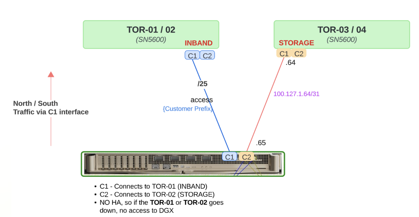
Figure 4 GB300 Cabling: C1 to TOR-01/02 (INBAND), C2 to TOR-03/04 (STORAGE). No HA; loss of TOR-01 or TOR-02 removes DGX access.#
Example Point-to-Point (P2P) format#
The following sample rows illustrate a manually formatted P2P extract. They use the same column layout as in Point-to-Point (P2P) format.
Example P2P in raw CSV format:
FLOW,FROM_RACK,FROM_RACKUNIT,CUSTOMER_SRC_NAME,FROM_NODE,FROM_PHYSICAL_PORT,FROM_PORT,FROM_BREAKOUT,TO_RACK,TO_RACKUNIT,CUSTOMER_DEST_NAME,TO_NODE,TO_PHYSICAL_PORT,TO_PORT,TO_BREAKOUT
NODE-DATA,A4,2,A4-10-S1-BCM-01,A4-10-S1-BCM-01,M1,M1,-,A3,8,A3-10-S1-BTOR-01,A3-10-S1-BTOR-01,1/1/1,1s0,4x
NODE-DATA,A4,5,A4-5-S1-BCM-02,A4-5-S1-BCM-02,M1,M1,-,A3,8,A3-10-S1-BTOR-01,A3-10-S1-BTOR-01,1/1/2,1s1,-
NODE-DATA,A4,8,A4-8-S1-MGMT-03,A4-8-S1-MGMT-03,M1,M1,-,A3,8,A3-10-S1-BTOR-01,A3-10-S1-BTOR-01,1/2/1,1s2,-
STORAGE-DATA,A5,20,A5-20-S1-HSS-05,A5-20-S1-HSS-05,S1,S1,-,A3,8,A3-10-S1-BTOR-01,A3-10-S1-BTOR-01,9/1/1,9s0,4x
IBSW-OOB,A3,43,A3-43-S1-IBLEAF-01,A3-43-S1-IBLEAF-01,bmc,bmc,-,A3,45,A3-10-S1-OOB-01,A3-10-S1-OOB-01,1,1,-
SW-OOB,A3,27,A3-27-S1-SPINE-01,A3-27-S1-SPINE-01,mgmt,mgmt,-,A3,45,A3-10-S1-OOB-01,A3-10-S1-OOB-01,9,9,-
UFM-OOB,A5,44,A5-44-S1-CUFM-01,A5-44-S1-CUFM-01,LOM3,LOM3,-,A3,45,A3-10-S1-OOB-01,A3-10-S1-OOB-01,23,23,-
NODE-OOB,A4,2,A4-2-S1-BCM-01,A4-2-S1-BCM-01,LOM2,LOM2,-,A3,45,A3-10-S1-OOB-01,A3-10-S1-OOB-01,30,30,-
PWR-OOB,A1,6,A1-6-S1-PWR-01,A1-6-S1-PWR-01,mgmt,mgmt,-,A3,46,A3-10-S1-OOB-02,A3-10-S1-OOB-02,1,1,-
UFM-DATA,A5,44,A5-44-S1-CUFM-01,A5-44-S1-CUFM-01,LOM1,LOM1,-,A4,45,A4-10-S1-FTOR-01,A4-10-S1-FTOR-01,1,1,-
STORAGE-OOB,A5,11,A5-11-S1-HSS-01,A5-11-S1-HSS-01,mgmt,mgmt,-,A5,41,A5-10-S1-OOB-01,A5-10-S1-OOB-01,1,1,-
EDGE-BTOR,-,-,EQX-EDGE-01,EQX-EDGE-01,-,-,-,A3,8,A3-10-S1-BTOR-01,A3-10-S1-BTOR-01,49/1/1,49s0,8x
SW-UPLINK,A3,14,A3-14-S1-TOR-01,A3-14-S1-TOR-01,53/1/1,53s0,2x,A4,42,A4-10-S1-SPINE-01,A4-10-S1-SPINE-01,1/1/1,1s0,2x
SW-UPLINK,A3,14,A3-14-S1-TOR-01,A3-14-S1-TOR-01,53/2/1,53s1,-,A4,42,A4-10-S1-SPINE-01,A4-10-S1-SPINE-01,1/2/1,1s1,-
DGX-DATA,A1,11,A1-11-S1-DGX-01-C01,A1-11-S1-DGX-01-C01,M1,M1,-,A3,14,A3-10-S1-TOR-01,A3-10-S1-TOR-01,1/1/1,1s0,4x
DGX-OOB,A2,12,A2-12-S1-DGX-02-C02,A2-12-S1-DGX-02-C02,BF1BMC,BF1BMC,-,A2,44,-,A2-10-S1-OOB-01,2,2,-
DGX-OOB,A1,12,A1-12-S1-DGX-01-C02,A1-12-S1-DGX-01-C02,BF1BMC,BF1BMC,-,A1,44,-,A1-10-S1-OOB-01,2,2,-
NVSW-OOB,A1,19,A1-19-S1-NVSW-01,A1-19-S1-NVSW-01,BMC,BMC,-,A1,45,-,A1-10-S1-OOB-02,9,9,-
The above csv data shown in an HTML table:
FLOW |
FROM_RACK |
FROM_RACKUNIT |
CUSTOMER_SRC_NAME |
FROM_NODE |
FROM_PHYSICAL_PORT |
FROM_PORT |
FROM_BREAKOUT |
TO_RACK |
TO_RACKUNIT |
CUSTOMER_DEST_NAME |
TO_NODE |
TO_PHYSICAL_PORT |
TO_PORT |
TO_BREAKOUT |
|---|---|---|---|---|---|---|---|---|---|---|---|---|---|---|
NODE-DATA |
A4 |
2 |
A4-2-S1-BCM-01 |
A4-2-S1-BCM-01 |
M1 |
M1 |
A3 |
8 |
A3-10-S1-BTOR-01 |
A3-10-S1-BTOR-01 |
1/1/1 |
1s0 |
4x |
|
NODE-DATA |
A4 |
5 |
A4-5-S1-BCM-02 |
A4-5-S1-BCM-02 |
M1 |
M1 |
A3 |
8 |
A3-10-S1-BTOR-01 |
A3-10-S1-BTOR-01 |
1/1/2 |
1s1 |
||
NODE-DATA |
A4 |
8 |
A4-8-S1-MGMT-03 |
A4-8-S1-MGMT-03 |
M1 |
M1 |
A3 |
8 |
A3-10-S1-BTOR-01 |
A3-10-S1-BTOR-01 |
1/2/1 |
1s2 |
||
STORAGE-DATA |
A5 |
20 |
A5-20-S1-HSS-05 |
A5-20-S1-HSS-05 |
S1 |
S1 |
A3 |
8 |
A3-10-S1-BTOR-01 |
A3-10-S1-BTOR-01 |
9/1/1 |
9s0 |
4x |
|
IBSW-OOB |
A3 |
43 |
A3-43-S1-IBCLEAF-01 |
A3-43-S1-IBCLEAF-01 |
bmc |
bmc |
A3 |
45 |
A3-10-S1-OOB-01 |
A3-10-S1-OOB-01 |
1 |
1 |
||
SW-OOB |
A3 |
27 |
A3-27-S1-SPINE-01 |
A3-27-S1-SPINE-01 |
mgmt |
mgmt |
A3 |
45 |
A3-10-S1-OOB-01 |
A3-10-S1-OOB-01 |
9 |
9 |
||
UFM-OOB |
A5 |
44 |
A5-44-S1-CUFM-01 |
A5-44-S1-CUFM-01 |
LOM3 |
LOM3 |
A3 |
45 |
A3-10-S1-OOB-01 |
A3-10-S1-OOB-01 |
23 |
23 |
||
NODE-OOB |
A4 |
2 |
A4-2-S1-BCM-01 |
A4-2-S1-BCM-01 |
LOM2 |
LOM2 |
A3 |
45 |
A3-10-S1-OOB-01 |
A3-10-S1-OOB-01 |
30 |
30 |
||
PWR-OOB |
A1 |
6 |
A1-6-S1-PWR-01 |
A1-6-S1-PWR-01 |
mgmt |
mgmt |
A3 |
46 |
A3-10-S1-OOB-02 |
A3-10-S1-OOB-02 |
1 |
1 |
||
UFM-DATA |
A5 |
44 |
A5-44-S1-CUFM-01 |
A5-44-S1-CUFM-01 |
LOM1 |
LOM1 |
A4 |
45 |
A4-10-S1-FTOR-01 |
A4-10-S1-FTOR-01 |
1 |
1 |
||
STORAGE-OOB |
A5 |
11 |
A5-11-S1-HSS-01 |
A5-11-S1-HSS-01 |
mgmt |
mgmt |
A5 |
41 |
A5-10-S1-OOB-01 |
A5-10-S1-OOB-01 |
1 |
1 |
||
EDGE-BTOR |
EQX-EDGE-01 |
EQX-EDGE-01 |
A3 |
8 |
A3-10-S1-BTOR-01 |
A3-10-S1-BTOR-01 |
49/1/1 |
49s0 |
8x |
|||||
SW-UPLINK |
A3 |
14 |
A3-14-S1-TOR-01 |
A3-14-S1-TOR-01 |
53/1/1 |
53s0 |
2x |
A4 |
42 |
A4-10-S1-SPINE-01 |
A4-10-S1-SPINE-01 |
1/1/1 |
1s0 |
2x |
SW-UPLINK |
A3 |
14 |
A3-14-S1-TOR-01 |
A3-14-S1-TOR-01 |
53/2/1 |
53s1 |
A4 |
42 |
A4-10-S1-SPINE-01 |
A4-10-S1-SPINE-01 |
1/2/1 |
1s1 |
||
DGX-DATA |
A1 |
11 |
A1-11-S1-DGX-01-C01 |
A1-11-S1-DGX-01-C01 |
M1 |
M1 |
A3 |
14 |
A3-10-S1-TOR-01 |
A3-10-S1-TOR-01 |
1/1/1 |
1s0 |
4x |
|
DGX-OOB |
A2 |
12 |
A2-12-S1-DGX-02-C02 |
A2-12-S1-DGX-02-C02 |
BF1BMC |
BF1BMC |
A2 |
44 |
A2-10-S1-OOB-01 |
2 |
2 |
|||
DGX-OOB |
A1 |
12 |
A1-12-S1-DGX-01-C02 |
A1-12-S1-DGX-01-C02 |
BF1BMC |
BF1BMC |
A1 |
44 |
A1-10-S1-OOB-01 |
2 |
2 |
|||
NVSW-OOB |
A1 |
19 |
A1-19-S1-NVSW-01 |
A1-19-S1-NVSW-01 |
BMC |
BMC |
A1 |
45 |
A1-10-S1-OOB-02 |
9 |
9 |
SiteInfo format#
Top · Point-to-Point (P2P) format · SiteInfo format · Factory inventory · NetworkDash UI
The siteinfo.yml (or siteinfo.yaml) file supplies site-wide values that netautogen merges with P2P and inventory data: DGX platform type, structured networking prefixes, and (in supported BCM releases) BGP ASN lists for edge-facing flows.
Refer to Example Point-to-Point (P2P) format for a concrete P2P extract in raw CSV and table form. Upload this file in the Network Auto Generate UI together with P2P CSV and rack inventory. A worked YAML example that includes time_servers, rack_mapping, and legacy BGP keys is in SiteInfo YAML example.
Networking keys#
The following keys belong under the networking mapping.
Key |
Required |
Description |
|---|---|---|
|
Yes |
String (CIDR). IP prefix for the headnode HA link. Must be at least |
|
No |
String (CIDR), optional. If set, it is split into |
|
Conditional |
String (CIDR). Required when |
|
Conditional |
String (CIDR). Required when |
|
No |
String (CIDR), optional. Defaults to |
The following keys are optional and are typically used for QA or smaller clusters (tune prefix lengths without changing the overall allocation model):
Key |
Type |
Default |
Description |
|---|---|---|---|
|
Integer |
|
Prefix length for OOB management segments. |
|
Integer |
|
Prefix length for DGX OOB. Example: |
|
Integer |
|
Prefix length for other OOB (for example PDU or power). |
|
Integer |
|
Prefix length for internal control-plane (internalnet). |
|
Integer |
|
Prefix length for DGX data networks (dgxnet*). How |
|
Integer |
|
Prefix length for Ethernet switch loopbacks. For alignment with DGX data on a new third-octet boundary, set |
|
Integer |
|
Prefix length for TOR to edge links. |
Tip
If DGX data (data_dgx_prefixlen) must start in a new third octet that is, on a fresh subnet whose host range begins at fourth octet .0, rather than using the second half of a /25 that still sits inside the same third octet as other allocations, set loopback_prefixlen to 25 instead of the default 27. That change shifts how address space is carved from data_prefix so DGX data begins at the next subnet boundary.
Note
BCM 11.32.0 and later
The following keys apply in BCM 11.32.0 and newer. (refer to SiteInfo YAML example).
Key |
Required |
Description |
|---|---|---|
|
Yes (BCM ≥ 11.32.0) |
List of BGP autonomous system numbers (not expressed as a single range). Used for switches that carry EDGE-SW data-plane flows from BTOR and FTOR switches when they have an EDGE-SW flow. Example: bgp_data_toedge_asn:
- 4260037001
- 4260037002
|
|
No |
List of BGP autonomous system numbers, optional. Used for OOBSPINE switches that have EDGE-SW flow. Example: bgp_oob_toedge_asn:
- 4260037101
- 4260037110
|
SiteInfo YAML example#
dgx_type: gb200 # or gb300 for GB300 deployments
networking:
# root_prefix: 10.0.0.0/20
oob_prefix: "7.241.0.0/21"
data_prefix: "7.241.16.0/21"
# The prefix for storage /31s.
storage_prefix: "100.127.0.0/16"
# MODIFIED TO SUPPORT SMALLER SUPERPODS
## ====================================
oob_prefix: 10.87.208.0/23
data_prefix: 10.87.210.0/24
# # The prefix ipminet0
oob_mgmt_prefixlen: 26
# # The prefix for PDU/Power
oob_other_prefixlen: 27
# # The prefix for DGX OOB
oob_dgx_prefixlen: 24
# INBAND NETWORK PREFIXES
# # internalnet for control plane
data_mgmt_prefixlen: 26 # internalnet
# # dgxnet for DGX racks
data_dgx_prefixlen: 25
# # loopback for loopback for ethernet switches
loopback_prefixlen: 27
# # edge for TOR <-> Edge connections
edge_prefixlen: 27
## ====================================
# The ASNs used for the BTOR and FTOR switches to carry EDGE-SW data-plane flows.
# Provided by the customer. Example:
bgp_data_toedge_asn:
  - 4260037001
  - 4260037002
- 4260037003
- 4260037004
# Mapping customer rack IDs (as used in the P2P file) to rack serial numbers (as
# provided by the factory). This is used to determine MAC addresses/serial
# numbers of devices in DGX racks (GB200/GB300).
rack_mapping:
A08: '1830625000808'
Factory inventory data example#
Top · Point-to-Point (P2P) format · SiteInfo format · Factory inventory · NetworkDash UI
Rack inventory CSV lists components and serials as shipped from the factory. For GB200 deployments, the supported source is typically an export from the Splunk Asset Rack Data board (CSV only). Use the export so column headers match what automation expects.
For step-by-step export from Splunk and a representative header-only CSV sample:
GB200 and GB300 Rack Inventory
For GB300 deployments, IP subnetting and rack grouping differ; refer to Subnetting Calculation for the GB300 subnetting plan.
How to pull rack inventory from the Splunk database
Use the following steps to pull rack inventory from the Splunk database:
Launch the URL — Open the Splunk DB (Asset Rack Data board) in your browser.
Select the factory index — In the Asset Rack Data form, open the Index dropdown and choose the factory index (for example, any foxconn or a specific site such as fxhc, fxlh, qsmc). Use the filter field to search if the list is long.
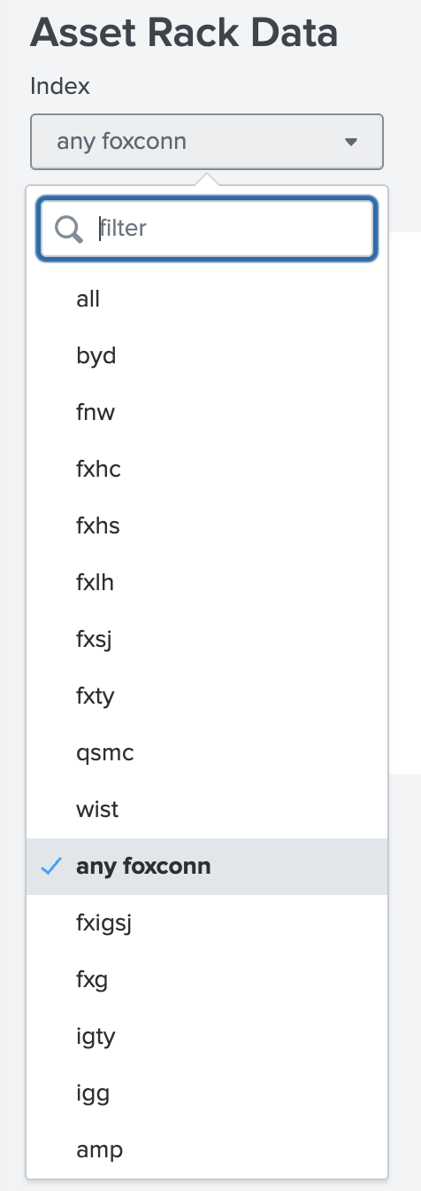
Figure 5 Asset Rack Data: use the Index dropdown to select the factory index.#
Enter the NVSN Rack Serial — In the form, enter the NVSN (rack) serial number for the rack whose inventory you want to retrieve.
Select the data range — Set the date range (earliest and latest) for the data you want to pull, then run the search to display the results.
Export to CSV — Scroll all the way down to the results area and move to the right. Use the download icon (arrow pointing down) to open the export options and choose to download the data in .csv format.
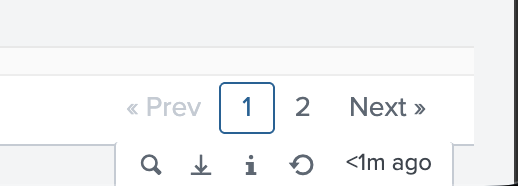
Figure 6 Export option: use the download icon (arrow pointing down) to download results in .csv format.#
After you click the download icon, the Export Results dialog appears. Set Format to CSV, optionally enter a File Name, and leave Number of Results blank to export all results (or enter a limit). Click Export to download the file.
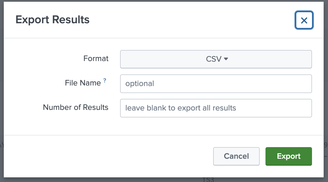
Figure 7 Export Results dialog: choose CSV format, optional file name, and number of results (leave blank for all), then click Export.#
The following CSV file is an example from the Splunk DB. The column header should have the following in the CSV file:
Note
The following CSV information consists entirely of column headers; there is no data content provided.
"COMP_PN","COMP_SN","COMP_SN_DIRECT_NVPN","COMP_SN_DIRECT_NVSN","COMP_TYPE",
DATECODE,LOCATION,NVPN,NVSN,"SCOMP_PN","START_TIME",VENDOR,"comp_pn","comp_sn",
"comp_type","date_hour","date_mday","date_minute","date_month","date_second",
"date_wday","date_year","date_zone",eventtype,filename,host,index,linecount,
location,nvpn,nvsn,punct,"scomp_pn",source,sourcetype,"splunk_server",
"splunk_server_group","start_time",starttime,tag,"tag::eventtype",
"tag::sourcetype",vendor,"_raw","_time"
NetworkDash UI#
Top · Point-to-Point (P2P) format · SiteInfo format · Factory inventory · NetworkDash UI