

Networking Planning and Design#
Logical Network Design#
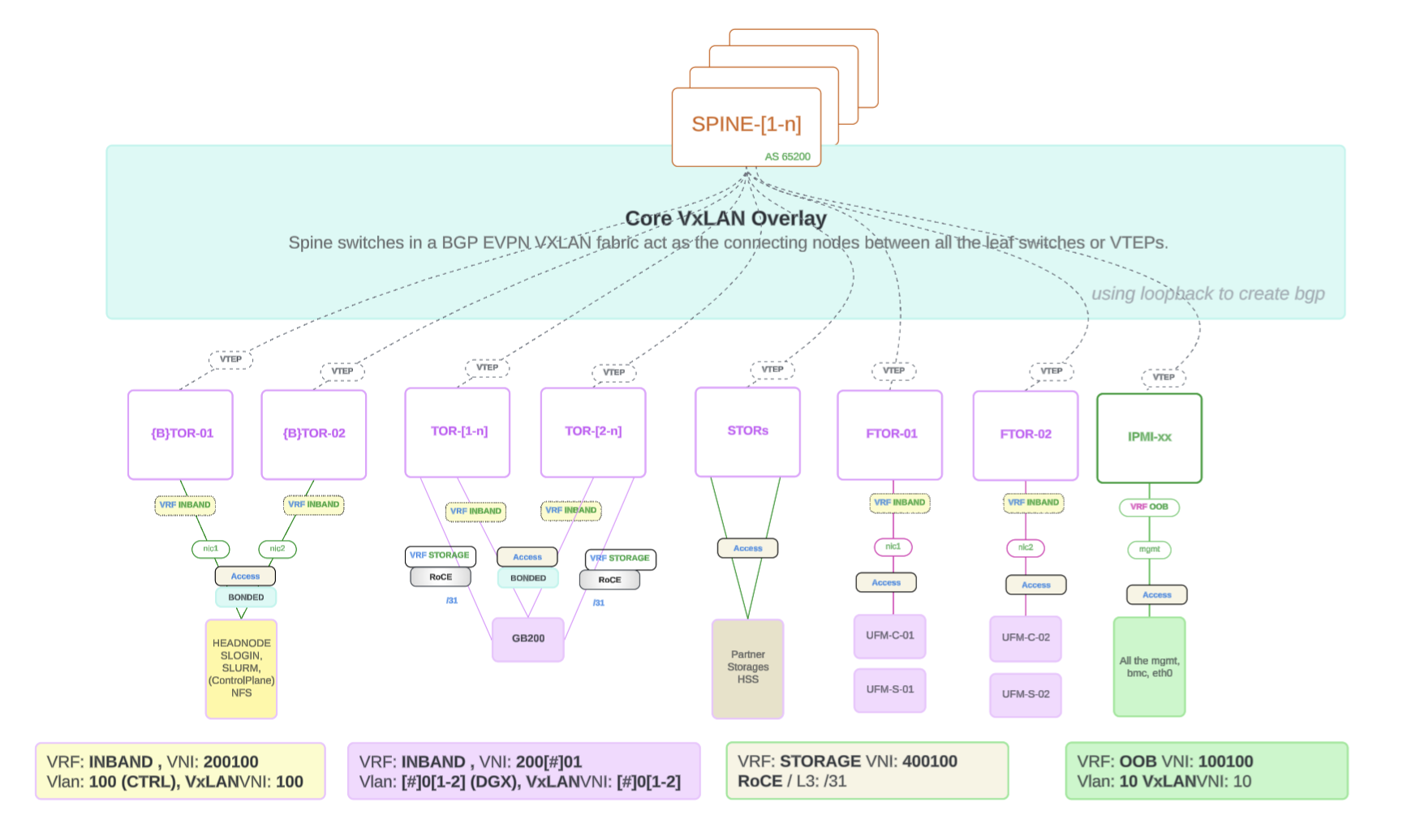
Figure 1 The Logical Network Design Architecture in Figure 1 applies to the GB200 system. The GB300 system utilizes the same high-level design principles, but with different subnet allocations as detailed in Table 4.#
Short Summary:
The following items provide a short summary of the logical network design:
BGP EVPN provides control plane signaling and tunnel discovery support in a VxLAN overlay network.
Loopback interfaces are commonly used for VTEPs (VXLAN Tunnel Endpoints) to establish BGP peering. Each VTEP is assigned a loopback IP address, which serves as a stable endpoint for routing EVPN control messages.
This approach enhances scalability and reliability, allowing for dynamic MAC address and IP address learning while maintaining tenant isolation. The VXLAN encapsulation enables seamless communication across the underlying network infrastructure, making it ideal for multi-tenant data centers and cloud environments.
Ethernet Networking (North-to-South)#
Data and OOB prefix layout#
Networks are provided by the customer and are further divided into an InBand (data) root prefix (in-band and related subnets) and an OOB prefix (out-of-band management). Example root ranges appear in the table titles; use your site’s actual prefixes. Sizes, VLAN IDs, and names are reference examples—align all values with your design and BCM configuration.
Network |
Size |
VLAN |
Purpose |
|---|---|---|---|
internalnet |
/24 |
100 |
InBand (data) control plane |
dgxnet[1-n] |
/25 |
10[1-n] |
For every 4 GB200 racks, there is one dgxnet1 subnet. |
dgxnet1 |
/24 |
10[1-n] |
For every 8 GB300 racks, there is one dgxnet1 subnet. |
loopbacks |
/27 |
– |
Loopbacks for all the VRFs (OOB, InBand, Storage) |
exit |
/31 |
– |
Customer Peering Subnet |
ipminet0 |
/23 |
201 |
Primary OOB (control plane, ethernet switch) |
ipminet1 |
/22 |
202 |
DGX BMC, IB switch COMe (DGX GB200/GB300 InRack OOB) |
ipminet2 |
/25 |
203 |
Secondary control plane OOB (PDU, Power, InfiniBand switch) |
Note
TOR to CE Transceiver Compatibility, refer to the Hardware Compatibility List (HCL)
We recommend that you review and refer to SuperPOD Network Requirements Document for more information.
Subnetting Calculation#
Use the following subnet calculator tool to determine the total number of subnets required for scaled deployments. Network Breakdown IP Plan Subnetting Calculator.
BGP ASN 4-Byte Range#
The following table shows the BGP ASN 4-byte range:
ROLES |
4-bytes ASN |
|---|---|
OOB |
4294902361 - 4294902460 |
TOR/STOR |
4294902461 - 4294902660 |
SPINEs |
4294902661 - 4294902750 |
SuperSPINEs |
4294902751 - 4294902760 |
Ethernet Planning#
Verify the hardware components for accuracy in model and quantity:
SN5600, SN5600D, SN5610 Ethernet switches
Transceivers (optical)
Cables (optical and copper)
Required NVLink Switch (NVOS) Version
The Software Bill of Materials (SBOM) for your Mission Control release lists the required NVLink Switch (NVOS) version.
Confirm Required Cumulus Linux Software Version
The SBOM for your Mission Control release lists the required Cumulus Linux version.
Fill out the “NVDA DGX SPOD GB200/GB300 Network Requirements” Excel file - Assuming in SIB
Content/Consideration List
Customer-Edge to Cluster connectivity
Transceiver type, compatibility and HW order status
Electrical signaling/encoding (NRZ vs PAM4)
Speed/Bandwidth
Uplink Quantity (transceiver, cable, fiber)
IP Addressing - P2P Uplinks
Routing protocol (default: BGP)
Routable IP Address Allocation
Discussed with and provided by the customer
Non-Routable IP Address Allocation
Use the default NVDA address ranges:
IB Compute =
100.126.0.0/16Ethernet Underlay =
10.254.0.0/16Ethernet Overlay Storage =
10.127.0.0/16
EVPN Planning Stage#
VRF / VLAN / VNI Mapping
Per scalable unit, InBand and OOB VLANs require L3VNIs. VRF-level identifiers are summarized in the following table.
VRF Type |
L3VNI |
L3VNI VLAN |
Purpose |
Route leaking |
|---|---|---|---|---|
OOB |
10010 |
1001 |
OOB control plane |
Import EXIT (optional) |
INBAND |
200100 |
2001 |
InBand data control plane and DGX |
Import EXIT (required) |
STORAGE |
400100 |
RoCEv2 high-speed storage |
||
EXIT |
Edge routing to external switches |
Export INBAND (required) & OOB (optional) |
Edge Network Handoff#
The edge network is the network that connects the SuperPOD to the customer’s network and includes the following:
In-Band management for all ControlPlane mgmt and handoff routes.
eBGP between Border TOR and Customer Edge: Establish an external Border Gateway Protocol (eBGP) session between the border leaf switches (which connect the EVPN fabric to external networks) and the CE devices. This allows the SuperPOD to advertise routes to the customer’s network and receive routes from the customer’s network.
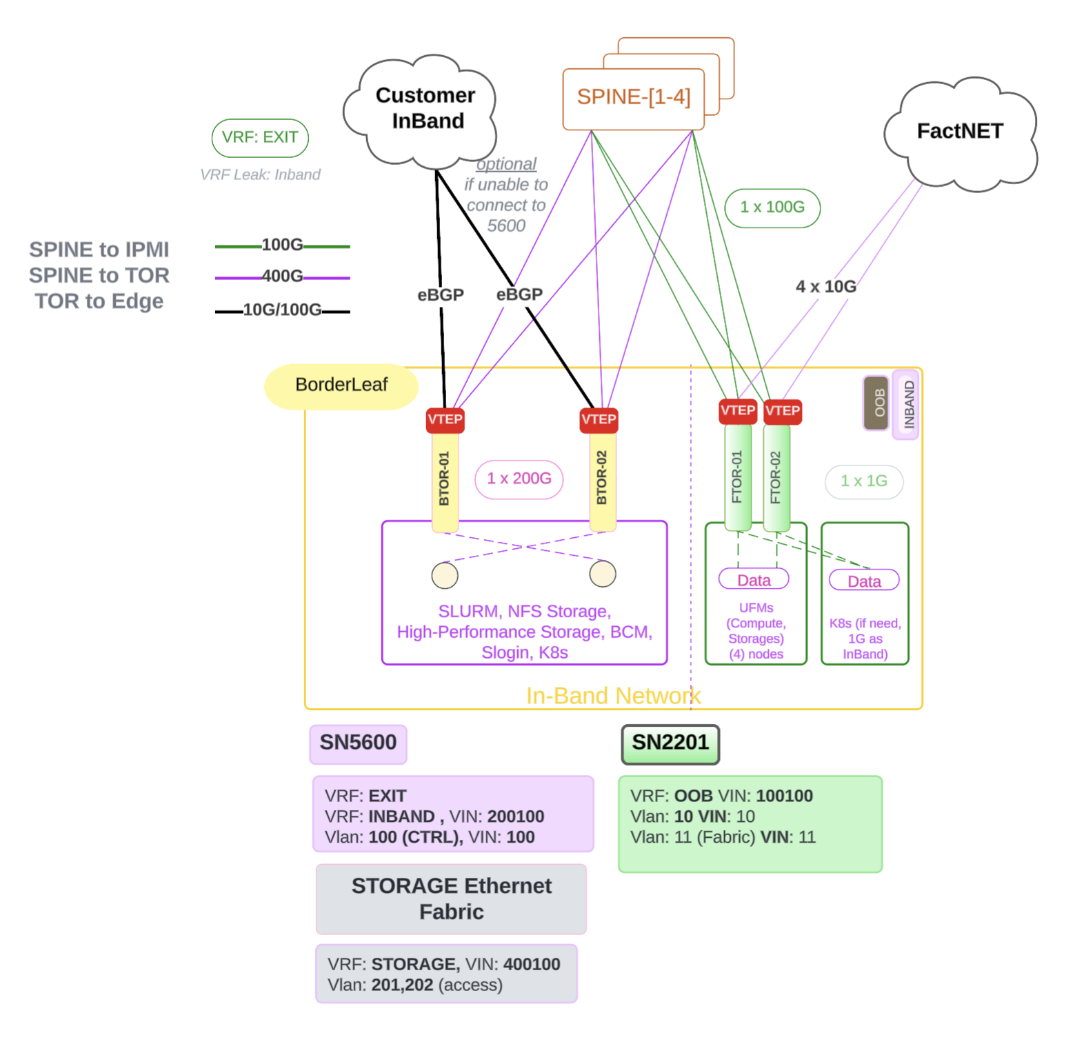
Figure 2 Edge Network Handoff#
InBand and OOB Handoff Separation (GB300)
On GB300 deployments, you can separate in-band and out-of-band (OOB) handoff to the customer by introducing an additional role called OOBSpine. The OOBSpine connects to the customer edge and receives a default route only into the OOB VRFs. This design allows you to leak routes through the BTOR (Border Leaf) for OOB connectivity while keeping in-band handoff and routing separate.
GB200 deployments do not use the OOBSpine role; use the standard edge handoff approach described preceding this subsection.
The following diagram shows the optional aggregated OOB handoff topology with the OOBSpine role on GB300:
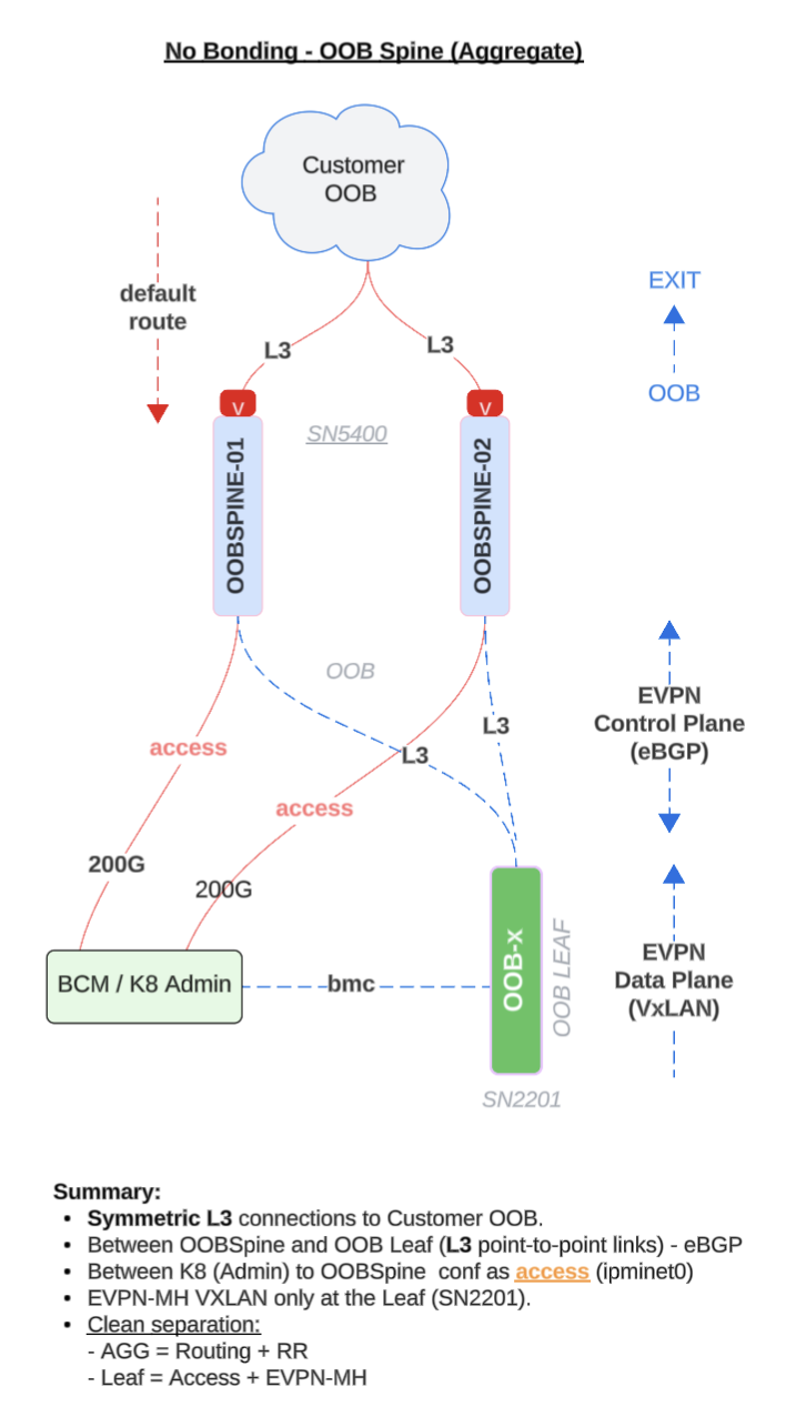
Figure 3 Additional aggregated OOB handoff: OOBSpine connects to customer and receives default route only into OOB VRFs.#
Topology (dual OOB spines, symmetric L3 uplinks to customer OOB)
Dual OOBSpine switches each have symmetric L3 uplinks toward customer OOB.
Kubernetes admin hosts attach to the OOB spines on access ports (shown as
ipminet0in designs)—host-facing links that can be L2 access or simple L3; they are not bonded.Between OOB Spine and OOB Leaf: L3 point-to-point links with eBGP.
EVPN runs only on the OOB leaf (for example, SN2201) for the VXLAN data plane.
There is no link aggregation (LACP), MLAG, or EVPN multihoming (EVPN-MH) in this aggregation tier: the host has two independent 200 Gbps paths (one per spine).
Design intent: keep the design simple and roles distinct, the spines focus on routing, the leaf provides EVPN/VXLAN and access (OOB VLANs, SVIs, and 1G OOB or BMC where applicable).
Roles in this aggregated OOB handoff design
OOB-Spine
L3 gateways toward customer OOB (default route into OOB VRFs as described preceding this figure)
eBGP to OOB leaf switches over routed uplinks
Host-facing access for Kubernetes and admin (dual attachment without bonding)
OOB-Leaf
EVPN/VXLAN for the OOB fabric data plane (for example, on SN2201)
1G OOB and BMC access where deployed
L3 routed uplinks to each OOBSpine (eBGP); OOB VLANs and SVIs
Server / admin
Dual-homed to both OOBSpine switches over separate links (no LACP bond)
High-bandwidth access; failover and load sharing follow routing and hashing (ECMP or host behavior), not LAG or EVPN-MH
Pros
Simpler design: No LACP, MLAG, or EVPN-MH at the aggregation layer—easier to deploy and troubleshoot.
Clear L3 underlay: eBGP on routed uplinks yields predictable routing; no L2 loops or spanning tree concerns in the fabric core.
Fault isolation: Failures are scoped per link or device; spines do not share aggregation state.
Clean role separation: Spine handles routing; leaf handles EVPN/VXLAN and access functions.
Operationally familiar: Aligns with teams that prefer traditional routed designs.
Cons
Suboptimal bandwidth use: Without bonding, the two 200 Gbps links are independent, there is no single 400 Gbps pipe, utilization depends on hashing (ECMP or host behavior).
Slower or less seamless failover: Without LACP or EVPN multihoming, convergence follows BGP timers and ECMP rehash rather than link-level redundancy semantics.
Access semantics: True L2 access can add VLAN and STP considerations; L3 on the host requires the operating system or workload to dual-home correctly.
No EVPN-MH at aggregation: You do not get active-active multihoming at the spine tier; dual attachment is less uniform than with EVPN-MH.
Uneven flow distribution: Independent links may not spread flows evenly across both paths without bonding or coordinated hashing.