

NVLink Switch Bringup Workflow#
This page covers NVLink Switch bringup in order. First it focuses on connections—physical ports, rack-side wiring, and how those links fit the OOB and rack design. Then it walks through bootstrap with BCM: integration checks, verification, firmware, and ZTP-style bringup as your release describes.
The workflow figure following gives the full path end to end; the sections under NVLink Switch Design unpack connectivity, and the material after that covers bootstrap and BCM verification.
The following diagram shows the bootstrap NVLink Switch workflow:
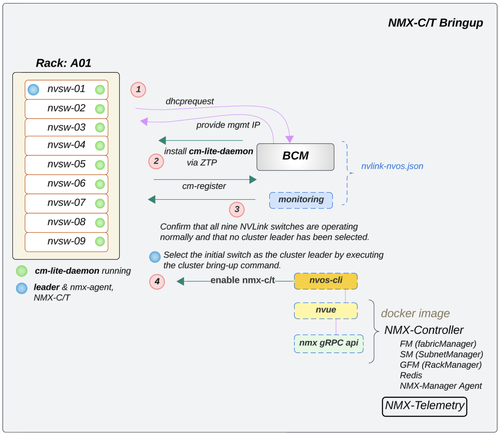
Figure 14 Bootstrap NVLink Switch workflow#
NVLink Switch Connectivity#
This section documents connectivity for the NVLink Switch design:
Physical connectivity (ComE, BMC to rack switch)
Network allocation on the OOB plan (multi-rack context)
The following diagram shows how the NVLink Switch connects to the Rack Switch using the NIC-COM ports and BMC on the OOB network.
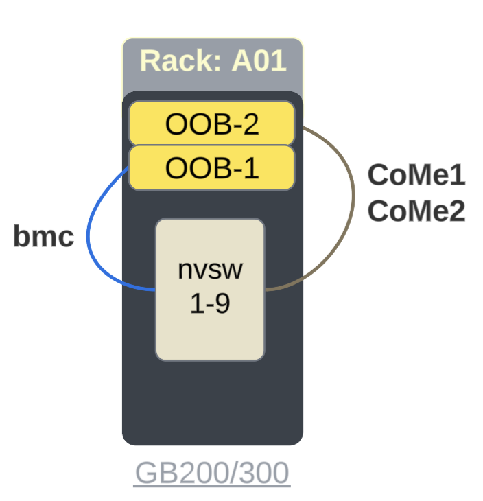
Physical Connectivity#
The following are the reference design for the NVLink Switch connectivity:
ComE1: 1G connects to within Rack Switch: SN2201 on RU 45
ComE2: 1G connects to within Rack Switch: SN2201 on RU 45
BMC: 1G connects to within Rack Switch: SN2201 on RU 44
Bootstrap with BCM#
NVLink Switch objects should already exist in BCM after bcm-pod-setup runs. bcm-netautogen (earlier in the same sequence) parses factory inventory and builds MAC-to-IP mapping. Both steps are described in BCM Bootstrap Workflow.
Here is few checklist items to validate before bootstrap:
InRack OOB switch been configured in BCM
InRack OOB switch been registered in BCM with cm-lite-daemon
InRack NVLink Switch has been power cycled
InRack NVlink Switch ComE0 is reachable from the BCM
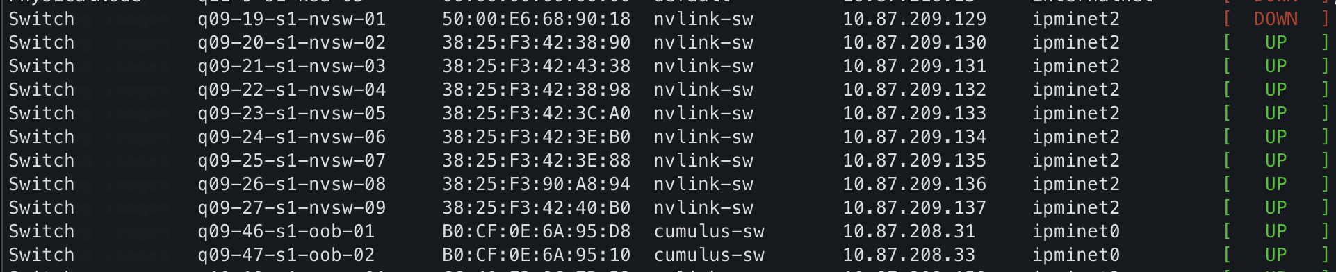
Figure 15 NVLink Switch Category in BCM#
Important
If the NVLink Switch comes pre-installed with NVOS from the factory and the factory password has already been reset, NVOS Zero Touch Provisioning (ZTP) service will be inactive.
Validating NVLink Switch Settings in BCM#
ZTP Settings Validation#
During the importing the NVLink Switch objects into BCM, tool will create a category called nvlink-sw and below ztpsettings will applied, so which it means per node setting is not required.
The following image shows the workflow diagram of NVLink Switch ZTP Settings:
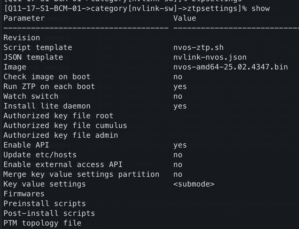
Figure 16 NVLink Switch ZTP Settings in BCM#
Power Control Validation#
From the BCM, the following commands can be tested to validate the power control login works (using factory or default credentials):
power status
When the password is incorrect versus correct (using root/<password>; the password varies by factory), the output differs. The following shows a failed login (invalid credentials) and a successful login (power status [ ON ]):
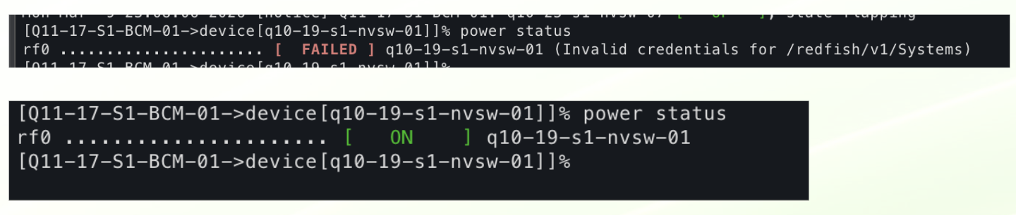
Figure 17 Power status: incorrect credentials (FAILED) vs correct credentials (ON).#
Power reset — Reboots the switch but has no effect if the ZTP service is disabled.
ZTP disabled from the factory — ZTP is disabled because it was either successful (NVOS then disables the service) or was not used.
Note
(Future) — An API call will be made to reset to factory default.
(Current) — Local script to reset to factory default:
nv action reset system factory-default force
Fm Config Validation#
From the BCM, the following commands can be tested to validate the fm config login works (using factory or default credentials):

Figure 18 Validate FM Config in BCM#
get fmconfigfile
Bringup NVLink Switch using ZTP#
Important
If the NVLink Switch is running a version earlier than v25.02.2134, the custom script and the cm-lite-daemon will not be installed.
However, once the NVLink Switch is upgraded to a newer version using ZTP, it will recognize the custom script option and install the cm-lite-daemon.
This process will take approximately 2-4 minutes longer than a standard ZTP.
The following flow diagram shows how the NVLink Switch is updated to the latest firmware:
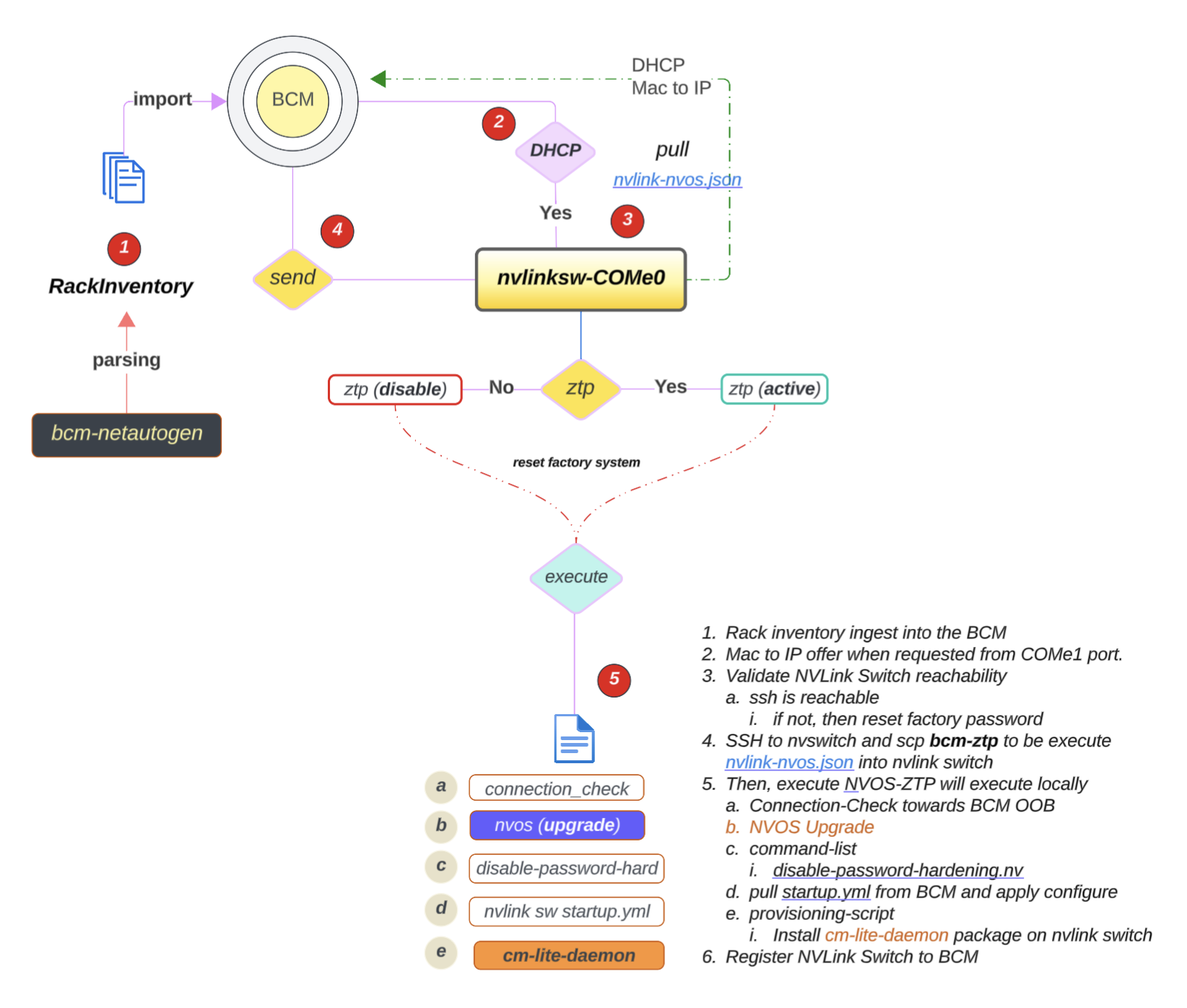
To update the NVLink Switch to the latest version, use the following steps:
If the NVLink Switch comes pre-installed with NVOS from the factory and the factory password has already been reset, NVOS Zero Touch Provisioning (ZTP) will be disabled.
The NVOS-ZTP script will be executed once the device is reachable.
Reset the NVLink Switch System to a factory reset.
Run the following command to reset the NVLink Switch System to a factory reset:
$ nv action reset system factory-default force
The NVLink Switch will reboot automatically (takes ~2.3mins)
Wait for the NVLink Switch to come back online.
On the backend, the following things will happen:
It will pull the nvlink-nvos.json file, validate the format, and create folders per section in
/var/lib/ztp/sections.It then executes each section one by one. For each section, it does the following:
Verifies network connectivity
Upgrades the NVOS image
Adjusts the security settings and disables password hardening
Applies the generated startup.yaml and patch configuration
Executes the nvos-ztp.sh script to install cm-lite-daemon, which does the following:
After the NVLink Switches are up and running within the rack, the system will automatically perform a Leader selection process
Out of 9, select 1 NVLink Switch:
Apply fm_config
Enable the cluster
Once the cluster is enabled, the NVLink Switch will be ready to use.