General Cooling Recommendations for Heatsink-less DPU Controllers
This section offers general cooling recommendations to NVIDIA customers who have acquired a heatsink-less DPU Controller (OPN: 900-9D3C6-00CV-GA0).
IMPORTANT NOTES:
The customer holds exclusive responsibility for the thermal design and for ensuring all board components never exceed their designated thermal operating limits.
The recommendations provided in this section are based on an air-cooled thermal design.
If the customer's environment has low or no airflow (e.g., liquid cooling) where the DPU Controller is to be installed, the customer must ensure proper cooling for all the other board components that are not covered by the recommendations of this chapter or in the product's thermal model. The customer must guarantee those components do not exceed their thermal operating limits as well.
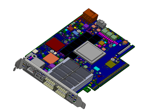
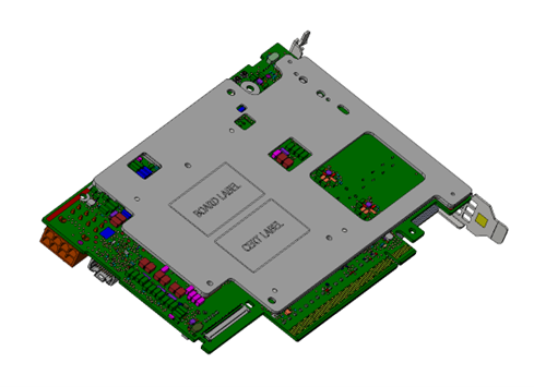
Isometric view of the heatsink-less DPU Controller:
Component Side | Print Side (with Stiffener) |
| 
|
The Thermal Transfer Plate (TTP) may encompass an internal liquid cooling system within a cold plate.
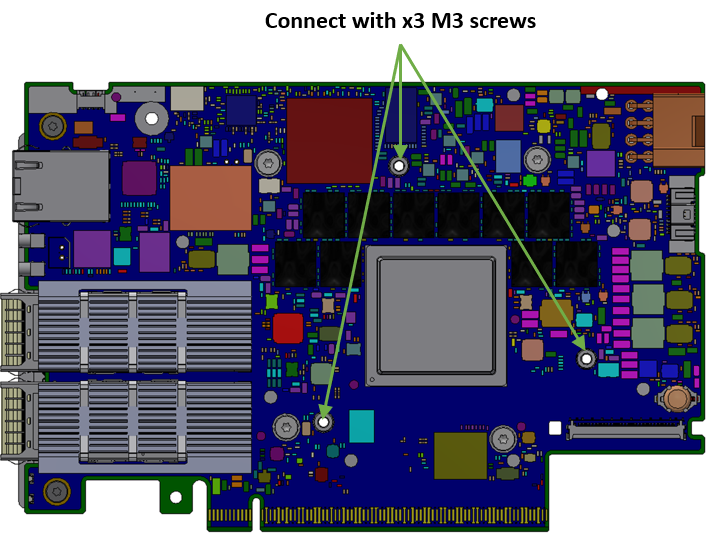
The M3 screws maximum protrusion length according to stiffener thread depth is listed in Mechanical Interfaces.
Recommended torque values: M3: 0.35~0.4 Nm. Use a locking mechanism.
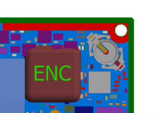
To ensure unobstructed access for replacement, ensure that the battery is not blocked. Refer to Encapsulation and Battery on SFG.
When considering encapsulation, ensure there is no interference with the TTP. The encapsulation is presented as the maximum tolerance on the SFG and is labeled with ENC. Refer to Encapsulation and Battery on SFG.
It is the responsibility of the customer to ensure proper cooling and thermal regulation for all components on the board. The provided guidelines are minimal and are based on NVIDIA's air-cooling thermal solution. Note the following:
The DPU controller SoC require contact with TTP on the component side of the product.
Within the air-cooled thermal solution, the cooling of components on the print side of the DPU controller is achieved via attachment to the board's bottom stiffener with the thermal interface material. See example in the board print side isometric view above.
The battery's thermal limitation is the maximum ambient temperature of 60°C.
The acceptable pressure on the SoC adheres to the following specifications:
35 psi (SoC area 761.5 mm²).
The center force should be applied at the center of the SoC.
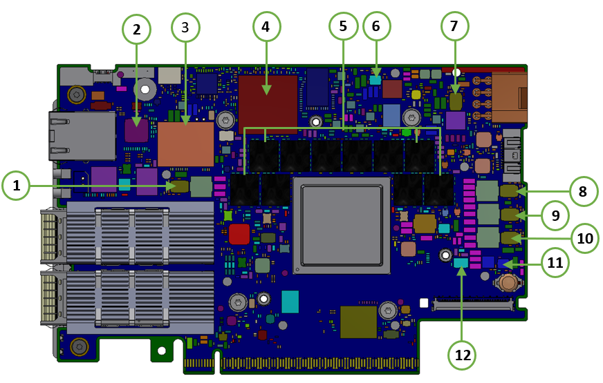
Component Side | Print Side (without Stiffener) |
| 
|
Item # | Board Components |
1 | U63 |
2 | U44 |
3 | M1394 |
4 | U99 |
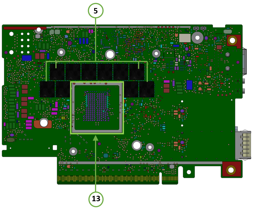
5 | M111-M115, M221-M225, M331-M335, M441-M445 |
6 | U30 |
7 | U66 |
8 | U62 |
9 | U64 |
10 | U65 |
11 | U32 |
12 | U33 |
13 | See marked square |
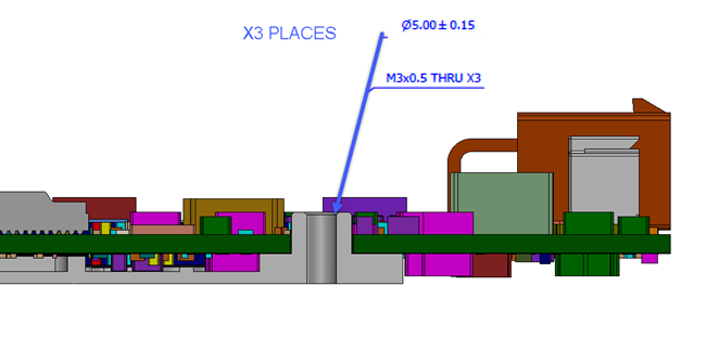
Mechanical Interfaces
The following figure lists the mechanical interfaces of the DPU controller.
Mechanical Interface | |
| 
|
Encapsulation and Battery on SFG
Ensure that the battery remains unobstructed to allow access for replacement. Furthermore, avoid any interference with the TTP. Note that the encapsulation is depicted as the maximum tolerance in the SFG and is labeled as ENC.