Multi-DPU Management from DPU BMC
BMC detects the cable connected on the 30-pin connector and comes up in a dual-DPU mode, in which the BMC provides the following management features of the second DPU connected through the 30-pin cable and the USB cable.
|
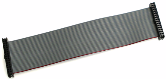
30-pin Cable |
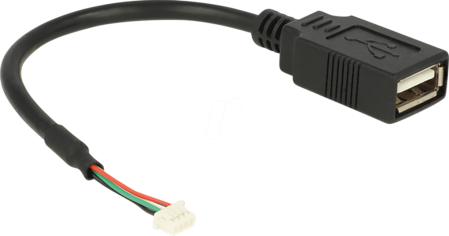
USB Cable |
|
|
For detailed pin description of the NC-SI BMC interface please refer to your DPU's hardware user manual.
Multi-DPU Management from DPU BMC Diagram
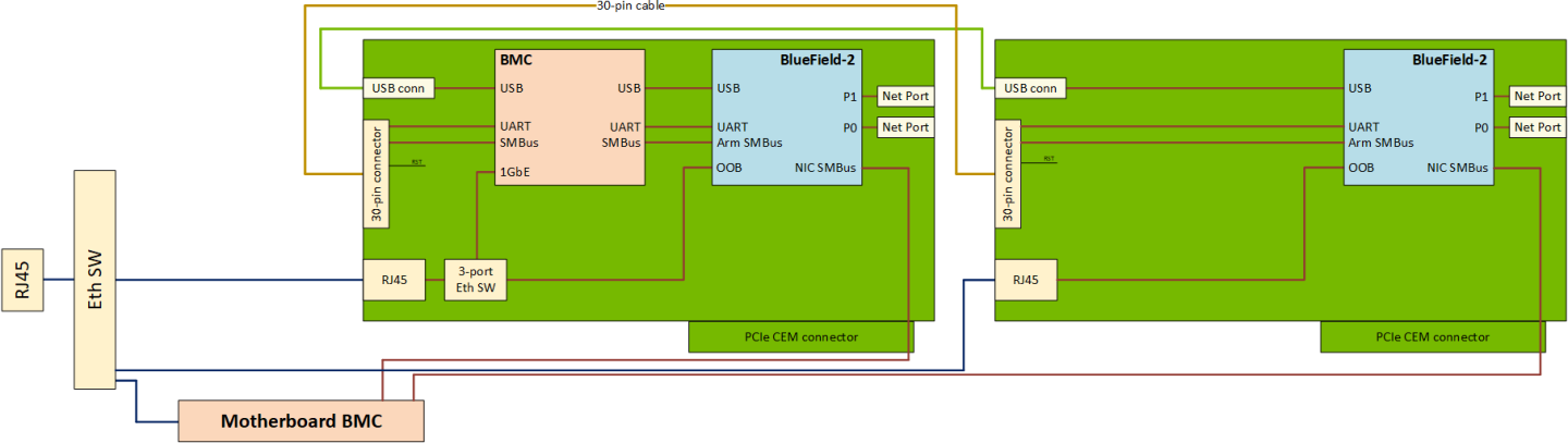
The secondary DPU is connected to BMC debug port UART5 for console access. All debug related usage of this UART on BMC (uboot logs, kernel logs and getty) are disabled in a dual mode operation.
Since the default SOL port of 2200 is used for the primary DPU, the SOL for the secondary DPU is provided on port 2201.
The IPMI SOL command will work only for the primary DPU (on-board), while user will have to use SSH-based console access.
SOL can be accessed with the following SSH command using root credentials:
ssh -p 2201 root@<NIC-BMC-IP>
The DPU BMC connects to the secondary DPU over the I2C bus on 30-pin cable to enable IPMI over IPMB.
On multi-DPU systems, the BMC will not aggregate the DPU’s IPMI model (specifically SDR, sensors, FRU and users) into its own IPMI model. It will only enable a bridge (IPMB) to the DPUs.
The BMC will not enable "DPU-specific" context for IPMI commands sent by the DPU firmware. Any such setting would apply to both the DPUs.
Users are able to use IPMItool chassis power commands (e.g. reset (soft), status) only for the primary DPU (on-board).
SDR Repository
All the SDR commands mentioned in Sensor Data Record (SDR) Repository are supported for the secondary DPU as well with the following IPMI over IPMB command format:
ipmitool -I ipmb -B 4 <ipmitool_arguments>
-B – 8-bit encoded address, used to target the secondary DPU with the following encoding
Warning-B is an optional argument, with default value of 0x00 which targets the primary DPU.
Bit 0-1 – IPMB channel type
0 – channel where BMC is the requester
1 – channel where BMC is the responder
Bit 2-7 – device index
0 – primary DPU
1 – secondary DPU
Reset Control
OEM command 0xA1 is defined for various reset controls of BlueField-2 from the BMC under the OEM NetFn group 0x32.
| Request | Response |
Reset Option |
|
|
|
The secondary DPU can be connected to the USB-A port on the BMC with an external USB cable, which would allow RShim over UBS on this interface.
RShim devices are enumerated in a random order in Linux and hence RShim 0 or1 are not tied to any of the DPUs. Users may pick a primary or secondary DPU depending on the information in /dev/rshimx/misc.
Network Connection
On the RShim interface BlueField takes 192.168.100.2 as its IP and configures 192.168.100.3 as the multicast address. So only 192.168.100.1 can be used as the IP for BMC. Therefore, the IP can only be set on one of the following interfaces at any time: tmfifo_net0 or tmfifo_net1. Since tmfifo_net<n> corresponds to rshim<n> interfaces, an IP may be configured on the relevant tmfifo_net<n> interface as follows:
ifconfig tmfifo_net1 192.168.100.1 netmask 255.255.255.0;
Before setting the IP for the next DPU, the IP address previously set may be deleted by running:
ip addr del 192.168.100.1 dev tmfifo_net1
Pushing Bootstream from BMC to BlueField-2 Arm on Secondary DPU
The process of pushing the BFB on the secondary DPU is as described in section Pushing Bootstream from BMC to BlueField-2 Arm.
System dump depends on the IP configuration of the RShim interface. Once the IP address is configured, system dump should behave as described in section System Dump Operations.