Kernel Representors Model
This model is only applicable when the DPU is operating ECPF ownership mode.
BlueField® DPU uses netdev representors to map each one of the host side physical and virtual functions:
Serve as the tunnel to pass traffic for the virtual switch or application running on the Arm cores to the relevant PF or VF on the Arm side.
Serve as the channel to configure the embedded switch with rules to the corresponding represented function.
Those representors are used as the virtual ports being connected to OVS or any other virtual switch running on the Arm cores.
When in ECPF ownership mode, we see 2 representors for each one of the DPU’s network ports: one for the uplink, and another one for the host side PF (the PF representor created even if the PF is not probed on the host side). For each one of the VFs created on the host side a corresponding representor would be created on the Arm side. The naming convention for the representors is as follows:
Uplink representors: p<port_number>
PF representors: pf<port_number>hpf
VF representors: pf<port_number>vf<function_number>
The diagram below shows the mapping of between the PCI functions exposed on the host side and the representors. For the sake of simplicity, we show a single port model (duplicated for the second port).
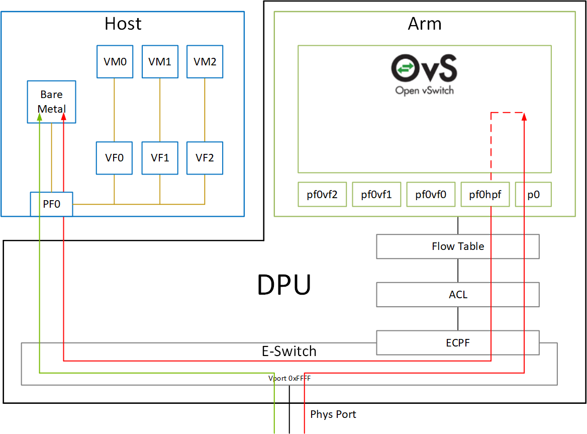
The red arrow demonstrates a packet flow through the representors, while the green arrow demonstrates the packet flow when steering rules are offloaded to the embedded switch. More details on that are available in the switch offload section.
The MTU of host functions (PF/VF) must be smaller than the MTUs of both the uplink and corresponding PF/VF representor. For example, if the host PF MTU is set to 9000, both uplink and PF representor must be set to above 9000.