FRU Insertion and Extraction (Hot-Swappable)
Before starting any procedure on the switch system, put an ESD prevention wrist strap on your wrist and connect to the chassis.
Do not mix replacement parts based on different generations of chip. All replacement modules must be consistent with the chassis family and switch chip generation.
When hot-swapping any of the units, it is necessary to wait 1 minute after removing the defective part before inserting the new part. This is necessary so that the management module will start a new cycle checking through the leafs and spines for the FW versions.
This switch platform supports hot swap capabilities for the following parts:
Power supply units
Leaf modules
Spine modules
Leaf fan modules
Spine fan modules
Management modules
For information on the ordering part numbers for these field replaceable units (FRUs), see Replacement Parts Ordering Numbers.
The power supplies deliver 2500W at 48VDC. The input to each of these power supplies requires 12A current in order to output 2500W.
For N+N configuration up to half of the PSUs can go down and the system will continue to run.
The power required to run the switch system is equally divided between all of the working PSUs.
Extracting and Inserting the PSU
With all of the N+N 2500W power supplies installed, the system is in N +N redundant configuration, half of the PSUs may be extracted without bringing down the system.
To extract a PSU:
Determine which AC connector on the connector side of the chassis corresponds to the defective PSU.
Remove the power cord from the PSU’s inlet. Note which power cord it is according to the AC numbering.
Power Unit AC Inlet Numbering

On the spine side of the chassis, remove the cover to the PSUs. There are four Phillips head screws for the cover plate.
Power Supply Unit

Grasping the handle with one hand, push the black latch release while pulling the handle outward. As the PSU unseats, the PSU status indicators will turn off.
Remove the PSU.
To insert a power supply unit:
Make sure the mating connector of the new unit is free of any dirt and/or obstacles.
Insert the PSU by sliding it into the opening until a slight resistance is felt.
Continue pressing the PSU until it seats completely. The latch will snap into place confirming the proper installation.
Insert the power cord into the supply connector on the other side of the chassis.
Replace the cover over the PSUs.
ImportantThe green indicators should light. If not, extract the PSU and re-insert it again.
When hot-swapping any of the units, it is necessary to wait 1 minute after removing the defective part before inserting the new part. This is necessary so that the management module will start a new cycle checking through the leafs and spines for the FW versions.
Leaf module slots are numbered from top to bottom from L1 to L6 on both sides of the chassis.
Extracting a Leaf Module
Each leaf module has 2 ejector handles that locks the module in place and serve as a lever for seating or extracting (see figure below).
Run the shut down command “no power enable <module>”. For example to shut down leaf 16 run the command below.
switch [master] (config) # no power enable L16
Disconnect all cables connected to the leaf.
Push the ejector handles in the direction of the red arrows in the figure below and pull them outwards to unlock the ejectors from the chassis.
Releasing Leaf Ejector Handles

Open the ejectors until it is 45 degrees from the leaf.
Pull out the module halfway through the guiding rails using the ejector handles.
Re-lock the ejector handles.
Hold the body of the leaf on both sides and remove it from the chassis.
ImportantThe module is short, therefore do not let go of it while sliding it out.
Inserting a Leaf Module
When hot-swapping any of the units, it is necessary to wait 1 minute after removing the defective part before inserting the new part. This is necessary so that the management module will start a new cycle checking through the leafs and spines for the FW versions.
To insert the leaf module:
Check for foreign objects in or mechanical damage to the chassis leaf slots.
Check leaf mechanics for any noticeable damage.
Check back signal connectors’ integrity. Look for any broken signal dividers or any deviations from the pass criterion shown below.
Intact Leaf Signal Connectors

Check the power connector’s integrity. Look for any damage on the power connector casing or blades damage.
Intact Leaf Power Pins

Start with the ejector handles fully open; that is, at 45 degrees to the front panel of the leaf.
Holding the leaf by its sides, carefully set the leaf module halfway into the chassis.
Applying equal pressure on both sides of the leaf module, and using only the ejector handles, slowly slide the module into the chassis until the ejector handles reach the vertical bar.
ImportantDo not apply excessive force to slide in the leaf module. If you feel resistance, remove the leaf module and double check both the chassis and leaf for any damage.
Catch the ejector handle hooks onto the vertical bar of the chassis and push the ejector handles shut.
Leaf Module Insertion

Lock the ejector handles onto the module.
Do NOT mix replacement parts based on different generations of chip. All replacement modules must be consistent with the chassis family and switch chip generation.
When hot swapping any of the units, it is necessary to wait 1 minute after removing the defective part before inserting the new part. This is necessary so that the management module will start a new cycle checking through the leafs and spines for the FW versions.
Each spine has a pair of ejectors that lock the module in place and serve as levers for seating or extracting (see the Releasing Spine Ejector Handles figure).
Management module 1 is connected to spine module 1, and management module 2 is connected to spine module 2. All of the spine modules can be hot-swapped when these two management modules are installed and working.
When a slave management module is not installed or not working, the spine module connected to the master management module cannot be hot-swapped.
Spine module slots are numbered from top to bottom from S1 to S6 on both sides of the chassis.
Extracting a Spine Module
When a slave management module is not installed or not working, hot-swapping the spine module connected to the master management module will cause the chassis to crash.
Neither the CLI nor the GUI management tools will allow you to shut down spine #1 or spine #2, as the management modules are connected to the chassis components through these spines.
Extracting Spine Module #1 or #2
Spine module #1 is connected to management module #1 and spine module #2 is connected to management module #2.
Management Module Numbering
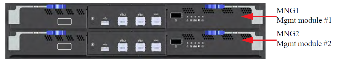
Removing spine #1 causes management module #1 to reset. Removing spine #2 causes management module #2 to reset.
Warning: If the spine you want to hot swap is connected to the master management module the management module will reboot when you take out the spine.
Do not extract spine 1 or 2 if only one management module is connected! Doing so will cause the switch system to hang which will lead to traffic loss.
If you need to hot swap spine #1 or spine #2:
Make sure that two management modules are connected to the switch system. See the Management Module Numbering figure above.
Extract the spine module according to the procedure in " Extracting Spine Modules Except #1 or #2" below starting with Step 2 (without running the shutdown command).
ImportantTraffic loss and errors in the log may be experienced momentarily.
Extracting Spine Modules Except #1 or #2
Run the shut down command no power enable <module>. For example to shut down spine 06 run the command below.
switch [master] (config) # no power enable S06
Push the ejector handles in the direction of the red arrows in the figure below and pull them outwards to unlock the ejectors from the chassis.
Releasing Spine Ejector Handles

Open the ejectors until they are at a 45 degree angle from the module.
ImportantDo not use the fan FRU handle to extract the spine module.
Pull out the module halfway through the guiding rails using both ejectors.
Re-lock the ejector handles.
Hold the body of the module on both sides and remove it from the chassis.
Inserting a Spine Module
When hot-swapping any of the units, it is necessary to wait 1 minute after removing the defective part before inserting the new part. This is necessary so that the management module will start a new cycle checking through the leafs and spines for the FW versions.
To insert a spine module:
Check for foreign objects in or mechanical damage to the chassis spine slots.
Check back signal connectors’ integrity. Look for any broken signal dividers or any deviations from the pass criteria shown in below .
Intact Spine Signal Connectors

Check power connector’s integrity. Look for any damage on the power connector casing or blades damage, or any deviations from the pass criterion shown in below.
Intact Spine Power Pin Holders

Start with the ejector handles fully open; that is, at 45 degrees to the front panel of the spine.
ImportantDo not use the fan FRU handle to insert the spine module.
Holding the spine by its sides, carefully set the spine module halfway into the chassis.
Using only the ejector handles, slowly slide the module into the chassis until the hooks reach the vertical bar.
ImportantDo not apply excessive force to slide in the spine module. If you feel resistance, remove the spine and double check both the chassis and spine for any damage.
Catch the ejector handle hooks onto the vertical bar of the chassis and push the ejector handles shut.
Spine Module Insertion

Lock the ejector handles onto the module.
Leaf Fan Module
A new system would have the PSU already installed so there
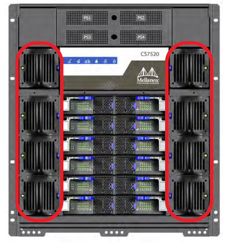
There are 8 fan modules on the chassis for the leaf and management modules. They are located on the spine side of the chassis with 4 on the right of the spines, and 4 on the left. When a fan module is not functioning the status LED on the fan will light up in amber. Airflow through the spines is independent of the airflow through the leafs.
Leaf Fan Locations on the Chassis
Extracting the Leaf Fan Module
Push and hold the blue latch release. See the figure below.
Slowly pull out the fan module using the handle.
Leaf Fan Module Extraction

Inserting the Leaf Fan Module
When hot-swapping any of the units, it is necessary to wait 1 minute after removing the defective part before inserting the new part. This is necessary so that the management module will start a new cycle checking through the leafs and spines for the FW versions.
Confirm that the location of the connector in the chassis lines up with the connector in the fan module.
Slowly slide in the new leaf fan module.
ImportantIf the fan module stops before it goes in all of the way it is inserted incorrectly.
Push the fan module until the latch engage
Make sure that the green fan LED on the module comes on (indicating that fan is running).
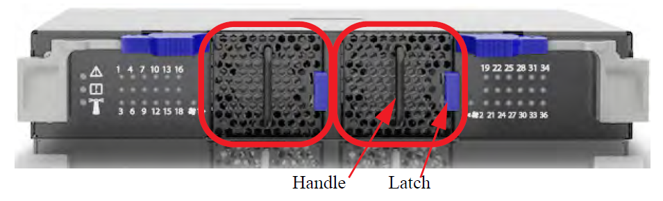
Spine Fan Modules
Each spine has 2 individual fan modules that contain 2 individual fans each. Should a single fan fail the fan status LED on the spine and the fan status LED on the management module light up, indicating the necessity to replace the fan module. Airflow through the spines is independent of the airflow through the leafs.
Spine Fan Modules
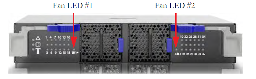
When a fan module is removed the indicator light will reset.
Fan Status LED on the Spine Module
Extracting the Spine Fan Module
To extract the spine fan module push the blue latch button while pulling the fan module out.
Inserting the Spine Fan Module
When hot-swapping any of the units, it is necessary to wait 1 minute after removing the defective part before inserting the new part. This is necessary so that the management module will start a new cycle checking through the leafs and spines for the firmware versions.
Make sure the fan module is oriented correctly with the release latch on the right. Confirm that the location of the connector in the chassis will line up with the connector in the fan module.
Slowly slide in the new spine fan module.
Push the fan module as far as it will go, make sure the locking latches engage.
ImportantIf the fan LED continues to show amber remove the fan module and check the pins on the connector inside of the spine to make sure that none of them are bent.
When hot-swapping any of the units, it is necessary to wait 1 minute after removing the defective part before inserting the new part. This is necessary so that the management module will start a new cycle checking through the leafs and spines for the FW versions.
Extracting a Management Module
Management modules are located on the leaf side, above the leafs. There are two slots to install the management modules.
Only one management module is required to run the switch system
If only one management module is used, the other management slot should be covered using a management blank unit.
Each management module has a pair of ejectors that lock the module in place and serve as a lever for seating or extracting (see the figure below).
Run the "shut down" command no power enable <module> . For example to shut down management module 2, run the command:
switch [master] (config) # no power enable mgmt2
Disconnect all cables connected to the management module.
Push the ejector handles in the direction of the red arrows in the figure below and pull them outwards to unlock the ejectors from the chassis.
Releasing Management Ejector Handles

Open the ejectors until they are 45 degrees from the module.
Pull out the module halfway through the guiding rails using the ejector handle.
Lock the ejector handle.
Hold the body of the module on both sides and remove it from the chassis.
ImportantThe module is short, therefore do not let go of it while sliding it out.
Inserting a Management Module
When hot-swapping any of the units, it is necessary to wait 1 minute after removing the defective part before inserting the new part. This is necessary so that the management module will start a new cycle checking through the leafs and spines for the FW versions.
To insert a management module:
Check for foreign objects in or mechanical damage to the chassis management slots.
Check management mechanics for any noticeable damage.
Check back signal connectors’ integrity. Look for any broken signal dividers or any deviations from the pass criterion shown below.
Intact Signal Connectors

Check power connector’s integrity. Look for any damage on the power connector casing or blades damage, or any deviations from the pass criterion shown in below.
Intact Management Power Pins

Start with the ejector handles fully open; that is, at 45 degrees to the front panel of the management.
Holding the management by its sides, carefully set the management module halfway into the chassis.
Using only the ejector handles, slowly slide the module into the chassis until the hooks reach the vertical bar.
ImportantDo not apply excessive force to slide in the management module. If you feel resistance, remove the management and double check both the chassis and management module for any damage.
Catch the ejector handle hooks onto the vertical bar of the chassis and push the ejector handles shut .
Management Module Insertion

Lock the ejector handles onto the module.
ImportantOn switch systems with dual management systems, first connect the cable and configure the master management module and only then configure the slave. By default the master is the top management module. For further information on the master and slave roles, see section “Subnet Manager (SM) High Availability (HA)” of the MLNX-OS® User Manual.
ImportantAll management modules in the chassis must go through an initial configuration procedure. See the Installation Guide for the initial configuration procedure.