Introduction
This chapter provides an overview of the CS7520 QSFP28 InfiniBand director switch platform (referenced in this document as “the chassis” or “the switch”) and its operational environment.
The Mellanox CS7520 switch system provides the highest performing fabric solution by delivering high bandwidth and low latency to enterprise data centers (EDC), high-performance computing (HPC) and embedded environments. Networks built with the CS7520 system can carry converged traffic with the combination of assured bandwidth and granular quality of service. Built with Mellanox’s 6th and 7th generation of Switch-IB™ and Switch-IB™ 2 switch devices, CS7520 systems provide up to 100Gb/s full bidirectional bandwidth per port. With up to 216 ports in a 12U rack space, this system is among the densest switching systems available.
The switch platform comes pre-installed with all necessary firmware for standard operation within an InfiniBand fabric and requires an InfiniBand compliant Subnet Manager running from one of the hosts or the management module of the switch system. The initial configuration procedure should be followed to initialize the switch before connecting it to the network after which normal operation can proceed. (See the installation guide for details regarding the initial configuration.) Once connected to the network, the Subnet Management software automatically discovers and configures the fabric and begins utilizing the switch.
The Mellanox Operating System (MLNX-OS®) software package provides a subnet manager and network management tools as well as connectivity software for servers and storage, and is available on the Mellanox website.
Basic installation is covered in Installation.
Hot-swapping components and hardware maintenance is covered in FRU Insertion and Extraction (Hot-Swappable).
Serial Number and Product Version Information
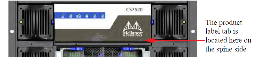
The serial number, GUID identifier and product version information are found on the label attached to the pull-out tab below the Mellanox logo on the spine side of the chassis.
Product Label
The GUID is the System Image GUID according to the IB spec. It is burned on the board which is in the chassis. All the boards and the management software look for this GUID in addition to their own Node GUID.
Product Label Tab Location
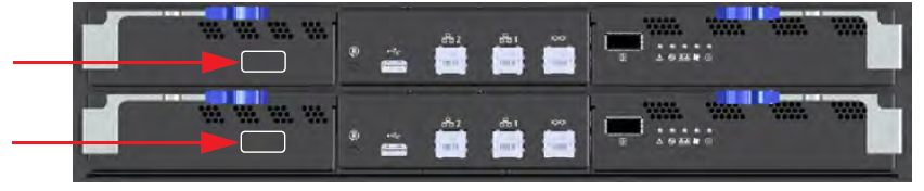
Management Module MAC
Each management module has a label with its MAC address. See the figure below for the location of this label.
Management Module MAC Address Location
Product Physical Specifications and Power
The switch itself is 12U tall but requires an extra 1U to install the shelf.
The switch ships in a minimum base configuration plus additional modules depending on the chosen customer configuration. Optional modules included:
Management modules
Spine modules
Leaf modules
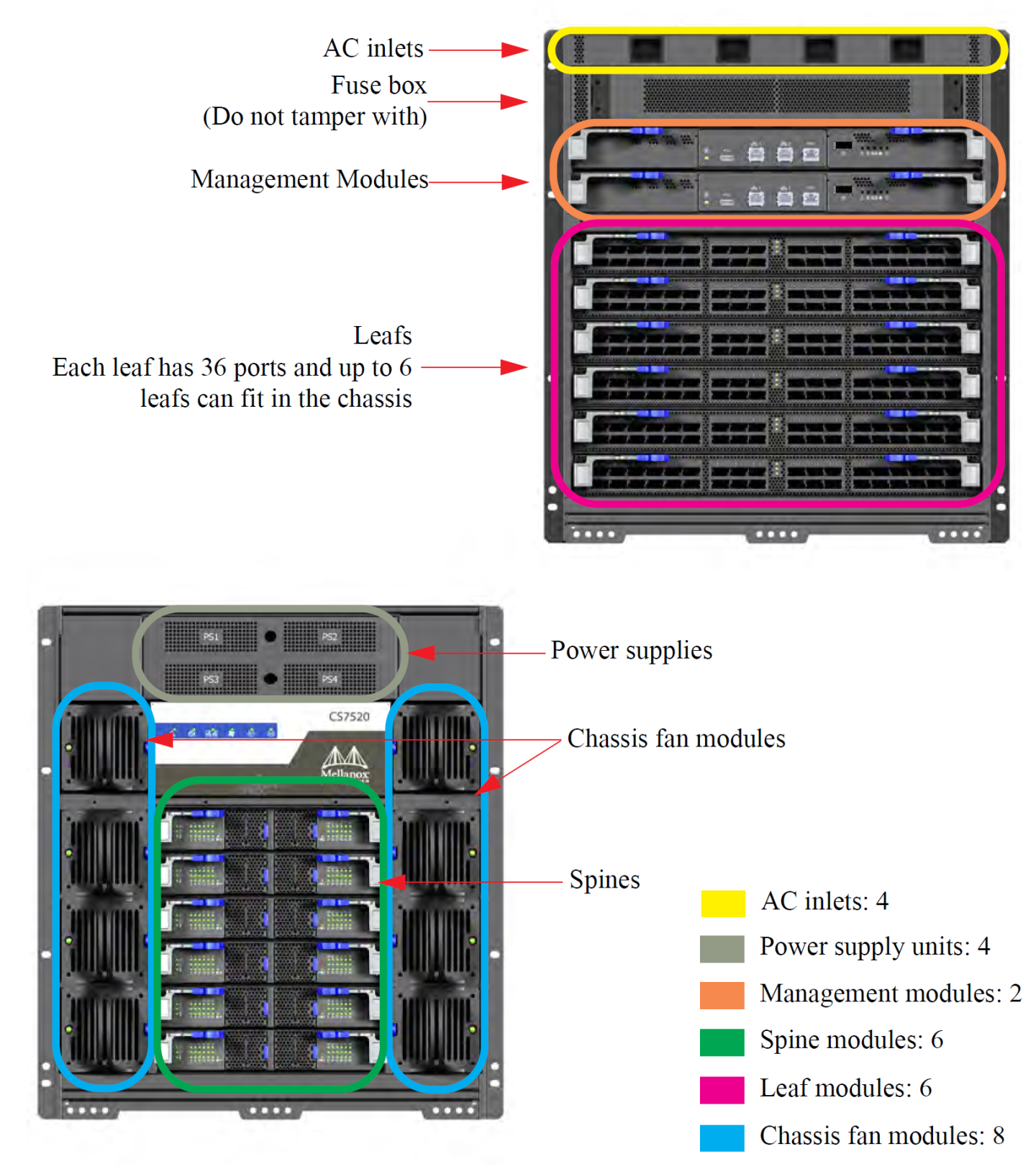
The following figure presents a fully populated leaf and spine side.
CS7520
216 EDR (100Gb/s) InfiniBand ports in a 12U switch
43 Tb/s aggregate data switching capacity with ultra low latency
IBTA 1.3 and 1.2.1 compliant
Up to EDR link speeds
N+N power supply
Chassis high availability
sMB high availability
The Mellanox CS7520 switch system supports EDR, standard InfiniBand data rate, where each lane of a 4X port runs a bit rate of 25.78125Gb/s. The EDR physical layer is an IBTA specified physical layer using different block types, deskew mechanism and framing rules.
Both FDR and EDR support Forward Error Correction (FEC), as described in IEEE Std 802.3ap-2007 (Amendment to IEEE Std 802.3-2005) chapter 74.
EDR is only guaranteed to work with approved Mellanox cables.
The CS7520 platform comes standard with 4 power supplies. Each power supply is capable to provide 48VDC 2500W output power.
The CS7520 system supports 220VAC operation only. No support for 110VAC source. Each AC source should be capable of providing at least 12A input current.
The minimum complement of PSUs which allows the chassis to run at full capacity is 2. The following two redundancy options are available:
No redundancy (combined mode)
All available PSUs are assigned to service the power budget. At maximum capacity, 2 PSUs are required but will not provide any failover. Any additional PSU added to the switch will raise the Power Budget and will be used for failover.
If the number of active PSUs cannot maintain a power budget larger than the maximum consumed power of all turned on modules, an "insufficientPower" warning will be sent and the software will turn off the FRUs.N+1 Mode (ps-redundant)
In this mode, one of the PSUs is reserved in the event of a failover. At maximum capacity, 3 PSUs are required. When 2 PSUs are operating, the switch will send a "lowPower" warning but continue to operate at maximum capacity.N+N configuration (grid-redundant mode)
“grid-redundant” mode, the power supplies are split into two logical power supply grids. The first half of the PSUs belong to grid A (PSUs #1 – #2) and the second half to grid B (PSUs #3 - #4).
The systems can work with only one grid and will utilize the minimum power budget between Grid A and Grid B.ImportantN+N redundancy only works with a supply voltage of 220V.
The chassis PSUs are fed from two power grids for high availability. The second power grid can be supplied by any of the following:
Backup power supply grid
Generator
Battery backup system
Any combination of the above
Connecting 2 power supplies to one power supply grid and the remaining 2 power supplies to a secondary power supply grid will create N+N redundancy for the power grids but does not cause any PSU failover at maximum capacity. This is high availability. Under these conditions should a power grid fail (an electric company power failure or blackout for example) power grid High Availability will continue to keep the chassis running at full capacity through the secondary or backup power supply grid.
The system cannot run with less than 2 PSUs, thus if one of the power grids is down there is no power or PSU redundancy in the system.
When the power drops below the required minimum due to power supply failure, MLNX-OS® may power down some leafs. If this happens it may be necessary to reboot the chassis once the defective PSU has been replaced. Two ways to reboot are to use the reboot command in the CLI or reboot through the WebUI.
Power Supply OPN
|
PSU OPN |
Wattage |
Description |
|
MTDF-PS-A |
2500W |
Supplies N+N redundancy for all switch chassis at 220 Volts |
Whether it is a chassis, or a spine fan unit, Mellanox’s EDR director switch chassis supports single fan failure without performance degradation.
When a fan unit fails, it must remain in the chassis until a replacement is available. At that point, the failed fan unit must be promptly replaced so that the chassis remains with an empty slot for as little time as possible.
· “grid-redundant” – the power supplies are split into two logical power supply grids, first half of the PSUs belongs to grid A (PSUs #1 – #5) and the second half to grid B (PSUs #6 - #10). The systems can work with only one grid and will utilize the minimum power budget between Grid A and Grid B.