Hardware Installation
Hardware: A system with a standard x8 PCIe slot.
OSs and Distributions: Please refer to Operating Systems/Distributions in the release notes.
The adapter is being installed in a system that operates with voltages that can be lethal. Before opening the case of the system, observe the following precautions to avoid injury and prevent damage to system components.
Remove any metallic objects from your hands and wrists.
Make sure to use only insulated tools.
Verify that the system is powered off and is unplugged.
It is strongly recommended to use an ESD strap or other antistatic device.
Safety warnings are provided here in the English language. For safety warnings in other languages, refer to the Adapter Installation Safety Instructions document available on mellanox.com.
Please observe all safety warnings to avoid injury and prevent damage to system components.
Note that not all warnings are relevant to all models.

| General Installation Instructions |

| Jewelry Removal Warning |
|
| Over-temperature |
|
| During Lightning - Electrical Hazard |
|
| Copper Cable Connecting/Disconnecting |
|
| Equipment Installation |
|
| Equipment Disposal |
|
| Local and National Electrical Codes |

| Hazardous Radiation Exposure
|
Verify that your system meets the hardware and software requirements stated above.
Shut down your system if active.
After shutting down the system, turn off power and unplug the cord.
Remove the card from its package. Please note that the card must be placed on an antistatic surface.
Check the card for visible signs of damage. Do not attempt to install the card if damaged.
The card is usually shipped with a tall bracket installed. If this form factor is suitable for your requirements, you can skip the remainder of this section and move to Card Installation Instructions.
If you need to replace it with the short bracket that is included in the shipping box, please follow the instructions in this section.
Due to risk of damaging the EMI gasket, it is not recommended to replace the bracket more than three times.
To replace the bracket you will need the following parts:
The new bracket of the proper height
The 2 screws saved from the removal of the bracket
The 2 fiber washers saved from the removal of the bracket
Removing the Existing Bracket
Remove the two screws holding the bracket in place. The bracket comes loose from the card.
WarningBe careful not to put stress on the LED.
Save the two screws and the two fiber washers.
Installing the New Bracket
Place the bracket onto the card until the screw holes line up.
WarningDo not force the bracket onto the card. You may have to gently push the LEDs using a small screwdriver to align the LEDs with the holes in the bracket.
Screw on the bracket using the screws and washers saved from the bracket removal procedure above.
Make sure that the LEDs are aligned onto the bracket holes.
Use a torque driver to apply up to 2.9 lbs-in torque on the screws.
Open the system case.
Place the adapter in a standard PCI Express slot.
Applying even pressure at both corners of the card, insert the adapter card into the slot until it is firmly seated. When the adapter is properly seated, the adapter port connectors are aligned with the slot opening, and the adapter faceplate is visible against the system chassis.
WarningDo not use excessive force when seating the card, as this may damage the system or the adapter.
To obtain the list of supported cables for your adapter, please refer to the List of Supported Cables in the release notes and http://www.mellanox.com/products/interconnect/cables-configurator.php.
Cable Installation
All cables can be inserted or removed with the unit powered on.
To insert a cable, press the connector into the port receptacle until the connector is firmly seated.
Support the weight of the cable before connecting the cable to the adapter card. Do this by using a cable holder or tying the cable to the rack.
Determine the correct orientation of the connector to the card before inserting the connector. Do not try and insert the connector upside down. This may damage the adapter card.
Insert the connector into the adapter card. Be careful to insert the connector straight into the cage. Do not apply any torque, up or down, to the connector cage in the adapter card.
Make sure that the connector locks in place.
WarningWhen installing cables make sure that the latches engage.
WarningAlways install and remove cables by pushing or pulling the cable and connector in a straight line with the card.
After inserting a cable into a port, the Amber LED indicator will light when the physical connection is established (that is, when the unit is powered on and a cable is plugged into the port with the other end of the connector plugged into a functioning port). See Network LEDs Operation.
After plugging in a cable, lock the connector using the latching mechanism particular to the cable vendor. When a logical connection is made, the Green LED will light. When data is being transferred the Green LED will blink. See Network LEDs Operation.
Care should be taken as not to impede the air exhaust flow through the ventilation holes. Use cable lengths which allow for routing horizontally around to the side of the chassis before bending upward or downward in the rack.
To remove a cable, disengage the locks and slowly pull the connector away from the port receptacle. LED indicator will turn off when the cable is unseated.
Xilinx Programming Cable
Xilinx programming cable is not provided by Mellanox, please contact your Xilinx representative for details.
The Xilinx programming cable is a USB to JTAG probe required to directly access the FPGA HW. Please refer to http://www.xilinx.com/products/boards-and-kits/hw-usb-ii-g.html.
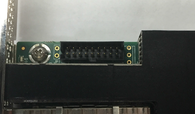
It is possible to connect the flat cable that comes with the Xilinx platform cable USB II to the on-board JTAG connector.
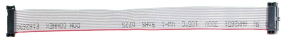
The on-board JTAG connector is 9 pins, dual row, 2mm pitch. The flat cable has a female connector 7 pins, dual row, 2mm pitch. The cable should be connected to the on-board connector according to the key in the shroud, (indicated with the yellow rectangle) leaving 2 unconnected pins on each side.
The other end of the Xilinx Platform Cable USB II should be connected to the user’s computer.
Get the device location on the PCI bus by running lspci and locating lines with the string “Mellanox Technologies”:
            lspci |grep -i Mellanox
Network controller: Mellanox Technologies MT28800 Family [ConnectX-5]