Using the Mellanox Innova-2 Flex Open Bundle
Mellanox provides the Mellanox Innova-2 Flex Open Bundle, which includes the Mellanox Innova-2 Flex Open FPGA Image and Mellanox Innova-2 Flex Open application. For detailed content of the bundle see Bundle Content and Considerations.
The bundle allows the user to:
Perform FPGA and board diagnostics - see Diagnostic Capabilities.
Burn a user image - see Burning Capabilities.
Determine whether the Mellanox Innova-2 Flex Open or the User Image will run on the FPGA - see Identifying the System State.
Important Notes:
If the Mellanox Innova-2 Flex image is not burned onto the card upon shipment, the user must burn the Mellanox Innova-2 Flex Image provided by Mellanox via JTAG. See Burning the FPGA Image through the JTAG.
The user can use the Mellanox Innova-2 Flex Open application to burn the user image and for FPGA interface diagnostics only if the FPGA Mellanox Innova-2 Flex Image is loaded. Otherwise, the application will display a reduced menu which only allows the user to load the Mellanox Innova-2 Flex Image.
When using the Mellanox Innova-2 Flex image, the user must work with the Mellanox Innova-2 Flex Open application only.
The user cannot overwrite the Mellanox Innova-2 Flex Image.
Copy the provided Mellanox Innova-2 Flex Open application package to a local temporary directory (i.e. /tmp).
Enter the temporary directory:
cd /tmp
Extract the Mellanox Innova-2 Flex Open application installation package:
tar zxvf Innova_2_Flex_Open_xx_xx.tar.gz
Navigate to the application folder (/app):
cd Innova_2_Flex_Open_xx_xx/app
Navigate to the driver folder (/driver):
cd Innova_2_Flex_Open_xx_xx/driver
Compile:
make clean; make
Run the application:
sudo ./innova2_flex_app -v
Detect the system’s state as instructed in Identifying the System State. If the system state is as shown in Example A, proceed to Step 3, if the system state is as shown in Example B or Example C, proceed to Step 4.
Perform the following:
Exit the application using the Exit option.
Navigate to the driver folder
cd ../driver/
Install the driver.
            make clean make
sudo insmod mlx_fpga_bope.ko
Return to Installing the Mellanox Innova-2 Flex Open Application.
You will now see the “Jump to Innova-2 Flex Image” menu with one single item: “Set Innova-2 Flex Image active”.
See Using the Mellanox Innova-2 Flex Open Bundle in order to change to the Mellanox Innova-2 Flex image.
Identifying the System State
Examples:
In the figure below, the Mellanox Innova-2 Factory Image is running, and there is no Mellanox Innova-2 FPGA PCI driver loaded.

In the figure below, the Mellanox Innova-2 Factory Image is running, and the Mellanox Innova-2 FPGA PCI driver is loaded. In the BOPE device info, the FPGA image version is displayed.

In the figure below, the Mellanox Innova-2 Flex Image is running, and the Mellanox Innova-2 FPGA driver is not loaded.

In the figure below, the Mellanox Innova-2 Flex Image is running, and the Mellanox Innova-2 FPGA PCI driver is loaded.

In the figure below, the User Image is running (the Mellanox Innova-2 FPGA PCI driver is not required).

Query FPGA version - reads the Mellanox Innova-2 Flex Image FPGA version and presents it to the user.
DDR Stress BIST (Built-in Self Test):
Cyclic test LFSR (Linear Feedback Shift Register) address - data, which can be either 1s, 0s or pseudo-random, is written to pseudo-random address until every DDR address is written to. The test then reads back the sequence and compares to the expected sequence. A new seed is used for the pseudo-random address sequence in every new cycle. The test continues until terminated by the user.
Cyclic test incremental address - data, which can be either 1s, 0s or pseudo-random, is written to incremental address until every DDR address is written to. The test then reads back the sequence and compares to the expected sequence. The test continues until terminated by the user.
Single test - writes data all over the DDR space and validates that data is written properly.
PCI test - tests the PCIe interface between the host and the FPGA.
FPGA Thermal status - reads the FPGA temperature and presents it to the user (in Celsius).
Fan speed - reads the Fan speed and presents it to the user (in RPM).
Increase FPGA power consumption - reads the FPGA power level, and presents it to the user. The user can set one of the FPGA power levels: 1, 2...10.
Running the Diagnostics
The Mellanox Innova-2 Flex Open bundle must be installed prior to the diagnostics.
To view the Mellanox Innova-2 Flex Open application options, run:
./innova2_flex_app -help
Run the application:
./innova2_flex_app -v
Check which image is active by reading the Running Image field. If the running image is Mellanox Innova-2 Flex, continue to Step 4. Otherwise, switch to Mellanox Innova-2 Flex Image, as instructed in Switching between Images.

Run the required tests or query, by choosing one of the menu options.
For DDR Stress Test - After selecting DDR Stress Test, the following screen should be shown:
Choose the type of the required test. Description of the different tests can be found in Diagnostic Capabilities.
In case the cyclic test was selected:
Press Enter to stop the test.
Wait for the test to finalize
Once finished, the test will print its result (success/fail)
Set FPGA power diagnostic.
In the Burn-Diagnostics menu, select Option 9 - “Increase FPGA power consumption”.

Upon selecting Option 9, the following menu should appear:

Choose the one of FPGA power levels. For example, Option 4, “Set FPGA Power level 4”. The following screen should appear:


JTAG Access to the FPGA
The Mellanox Innova-2 Flex Open Application access to FPGA may interfere with the on-board JTAG access to FPGA. If external JTAG cable access is required (for example, see Burning the FPGA Image through the JTAG) the application must first enable this.
Select the "Enable JTAG Access - no thermal status" in the "Jump-to Innova2-Use" menu, or in the "Burn-Diagnostics" menu.

The FPGA is now disconnected, and you can burn the FPGA image through the JTAG.
After burning, you can connect the FPGA by selecting "Disable JTAG Access - enable Thermal status”, and continue working with the Mellanox Innova-2 Flex Open application.

Disconnect the FPGA, and check the status.

The “Disconnect” state is saved when the Mellanox Innova-2 Flex Open application is closed. After running the Mellanox Innova-2 Flex Open application, the system is in “Disconnected” state.

Close the application and start burning Flex through the JTAG.
After burning and following the power cycle, open the application and select the “Connect FPGA” option in the "Disconnected" menu.
Note: The Mellanox Innova-2 Flex Open bundle must be installed prior to the image burning.
The Mellanox Innova-2 Flex Open application and image allow the user to burn an FPGA User Image to the flash through the PCI, and to switch back and forth between the images that run on the FPGA - the Mellanox Innova-2 Flex Image and the User Image. After burning and activating the User Image, the user can return to the Mellanox Innova-2 Flex Image (for diagnostics or PCI-burn).
Running the Burning Flows
To view the Mellanox Innova-2 Flex Open application options:
innova2_flex_app -help
To run the application, see the below example:
To program two files at flash 0 and flash_1:
/innova2_flex_app -b first_file_name.bin,
0second_file_name.bin,1-v
When the application opens, choose “Burn of customer User image” to burn the image.
During the burning process the application will show progress and a message will indicate once burn is done.
For activating the burned image, see Switching between Images.

The user can determine which image from the Flash will run on the FPGA.
In case the FPGA User Image is corrupted and/or does not exist but the user chose to set it as active, the booting action will fail and the FPGA will appear un-programmed after reboot.
Open the application:
./innova2_flex_app -v
In case the Mellanox Innova-2 Flex Image is running, select the “Switch to Innova-2 Flex Image” option in order to move to the Mellanox Innova-2 Flex Image.
In case User Image or no image is running, choose the “Switch into Innova-2 Flex Image” option in order to move to the Mellanox Innova-2 Flex Image.
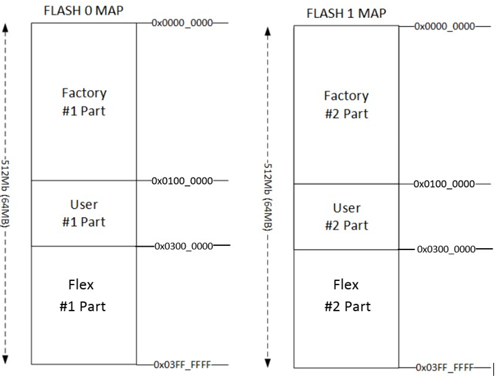
Flash Format
The below figure shows the flash format when both the Mellanox Innova-2 Flex Image and User Image are burned on the flash (i.e. when the Mellanox Innova-2 Flex Image is not overwritten).
Burning an FPGA image via JTAG should be done from an external server connection. Dropping a PCI link during FPGA burning can cause the server to stall and self-reboot, thereby causing the burning process to fail. When JTAG is connected to an external server, even if the target server stalls, the burning process will complete successfully.
To burn the Flash via Vivado Lab Edition 2017.3:
If the Mellanox Innova-2 Flex Open Application is running, it may interfere with the JTAG connectivity. See JTAG Access to the FPGA before you connect a JTAG cable.
Go to the following link, and install Vivado Lab Edition 2017.3 - https://www.xilinx.com/support/download/index.html/content/xilinx/en/downloadNav/vivado-design-tools/2017-3.html.
Connect the JTAG cable. For information on JTAG connection, see Xilinx Programming Cable.
Xilinx programming cable is not provided by Mellanox, please contact your Xilinx representative for details.
To add a configuration memory device:
Open Vivado Lab Edition 2017.3.
Click “Open Target” and then “Auto Connect”.
Click on the “Open Hardware Manager.”
On the left corner (Hardware) - make sure you can see 'xcku15p' device.
Right click on the 'xcku15p' and 'Add Configuration Memory Device'.

Select the appropriate device (x1_x2_x4 or x1_x2_x4_x8).

Choose the BIN file. See Bundle Content and Considerations.

Burn the flash.
Run server full power cycle.
Reloading is the customer’s responsibility. Errors can lead to a failure of the Mellanox Innova-2 adapter card, and even to a failure of the server. The link between the FPGA and the PCI switch should be disabled before reloading the FPGA User Image, and enabled after reloading. Two consoles are used: the console where the Innova2_Flex_app is running, and the console for PCI commands.
Procedure Scenario
In order to reload the Mellanox Innova-2 User Image, start the first console, and launch the Innova2_flex_app, as instructed in Running the Mellanox Innova-2 Flex Open Application. The second terminal should be open, as it is used for disabling/enabling the PCI link between the FPGA and the PCI switch.
In the second console:
Step 1. Find the PCI switch in the list of PCI devices.
Step 2. Save the FPGA device PCI configuration registers.
Step 3. Disable the PCI link between the FPGA and the PCI switch.
In the first console:
Step 4. Reload the FPGA User Image.
Move back to the second console:
Step 5. Enable PCI link between FPGA and PCI switch (second console).
Step 6. Copy back the PCI configuration registers (second console).
Finding the PCI Switch
Get the device location on the PCI bus by running the below lspci command, and locating lines with the "Mellanox" string, as instructed in Identify the Card in Your System.
lspci -v | grep Mellanox
Example:
ConnectX5 Device has 3e:00.0 PCI bdf ( [bus:][device.][func] ) address
Mellanox Innova-2 FPGA PCI driver (BOPE-driver) has 3d:00.0 PCI bdf address
The PCI switch has 3c:08.0 bdf address

Disabling/Enabling the PCI Link between the FPGA and the PCI Switch
Disabling example:
sudo setpci -s 3c:08.0 0x70.w=0x50
Enabling example:
sudo setpci -s 3c:08.0 0x70.w=0x40
Examples legend:
3c:08.0 is the bdf address of the PCI switch
0x70 is the capability register base address + link control register (0x60+0x10)
0x40 is the last value in this register
0x50 is the last value in this register + disable link bit (0x40 + 0x10)
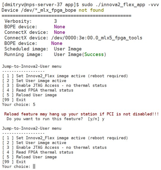
Reloading the User Image
In the Burn-Diagnostic Menu, select Option 5 - "Reload User image”. The following message will appear:
"Reload feature may hang up your station if PCI is not disabled!!! Do you want to run this feature? [y/]"
Make sure that the PCI link is disabled, as instructed in Disabling/Enabling the PCI Link between the FPGA and the PCI Switch.
Enable the PCI link on the second console, as instructed in Disabling/Enabling the PCI Link between the FPGA and the PCI Switch.