Specifications
Absolute maximum ratings are those beyond which damage to the device may occur.
Between the operational specifications and absolute maximum ratings, prolonged operation is not intended and permanent device degradation may occur.
|
Parameter |
Min |
Max |
Max |
|
Supply Voltage |
-0.3 |
3.6 |
V |
|
Data Input Voltage |
-0.3 |
3.6 |
V |
|
Control Input Voltage |
-0.3 |
3.6 |
V |
This table shows the environmental specifications for the product.
|
Parameter |
Min |
Max |
Units |
|
Storage Temperature |
-40 |
85 |
°C |
This section shows the range of values for normal operation.
|
Parameter |
Min |
Typ |
Max |
Units |
|
Supply Voltage (Vcc) |
3.135 |
3.3 |
3.465 |
V |
|
Power Consumption |
-- |
-- |
0.1 |
W |
|
Operating Case Temperature |
0 |
70 |
°C |
|
|
Operating Relative Humidity |
5 |
85 |
% |
|
Parameter |
Min |
Typ |
Max |
Units |
Note |
|
Characteristic impedance |
90 |
100 |
110 |
Ω |
|
|
Time propagation delay |
-- |
-- |
4.5 |
ns/m |
Informative |
|
Parameter |
Value |
Units |
|
|
Diameter |
30AWG: 5.7 ±0.03 26AWG: 7.1 ±0.03 |
mm |
|
|
Length tolerance |
length < 2 m |
±25 |
mm |
|
length ≥ 2 m |
±50 |
||
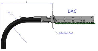
Minimum Bend Radius
|
OPN |
Length (m) |
AWG (mm) |
Cable Diameter |
Min bend radius R (mm) |
Assembly Space L** Combined/Single end (mm) |
|
MCP7Y40-N001 |
1.0 |
30AWG, 4x4pairs |
5.7 |
57 |
117/111 |
|
MCP7Y40-N01A |
1.5 |
30AWG, 4x4pairs |
5.7 |
57 |
117/111 |
|
MCP7Y40-N002 |
2.0 |
26AWG, 4x4pairs |
7.1 |
71 |
134/127 |
|
MCP7Y40-N02A |
2.5 |
26AWG, 4x4pairs |
7.1 |
71 |
134/127 |
|
MCP7Y40-N003 |
3.0 |
26AWG, 4x4pairs |
7.1 |
71 |
134/127 |
Minimum assembly bending radius (close to the connector) is 10x the cable’s outer diameter. The repeated bend (far from the connector) is also 10x the cable’s outer diameter. The single bend (far from the connector) is 5x the cable’s outer diameter.
**’Combined’ end is the ‘head’ where the cables join together, inserted into the switch. ‘Single’ end is the ‘tail’ which plugs into the HCA/NIC in a server.
L = Assembly Space. Minimum value depends on the backshell (connector housing) dimensions = the space for the cable assembly behind the rack door.
Assembly Bending Radius
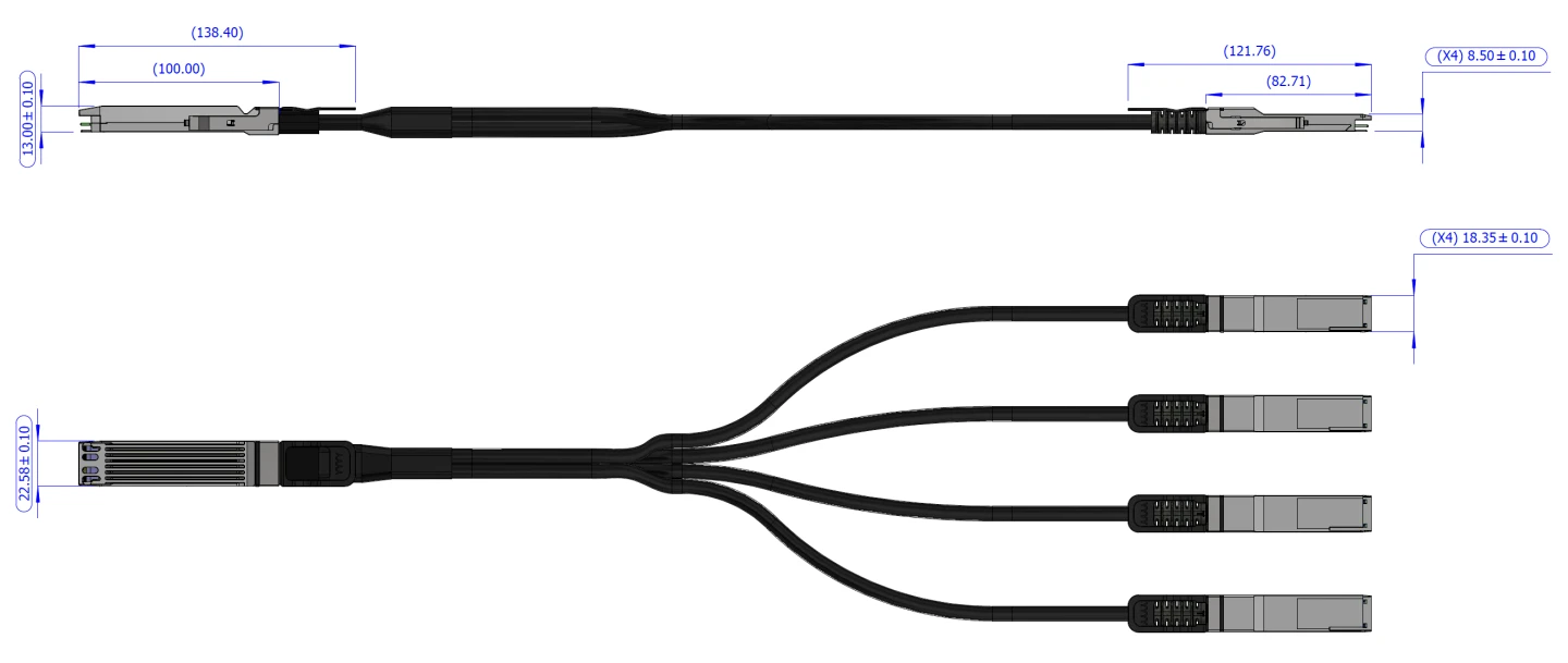
Cable Dimentions
|
Head/End |
Tab Color |
|
OSFP (head) |
Black |
|
QSFP112 Port 1 (End) |
Green |
|
QSFP112 Port 2 (End) |
Blue |
|
QSFP112 Port 3 (End) |
Yellow |
|
QSFP112 Port 4 (End) |
Red |
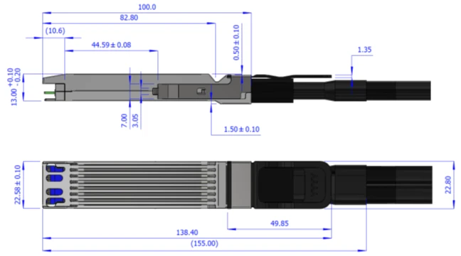
Finned Head Dimensions
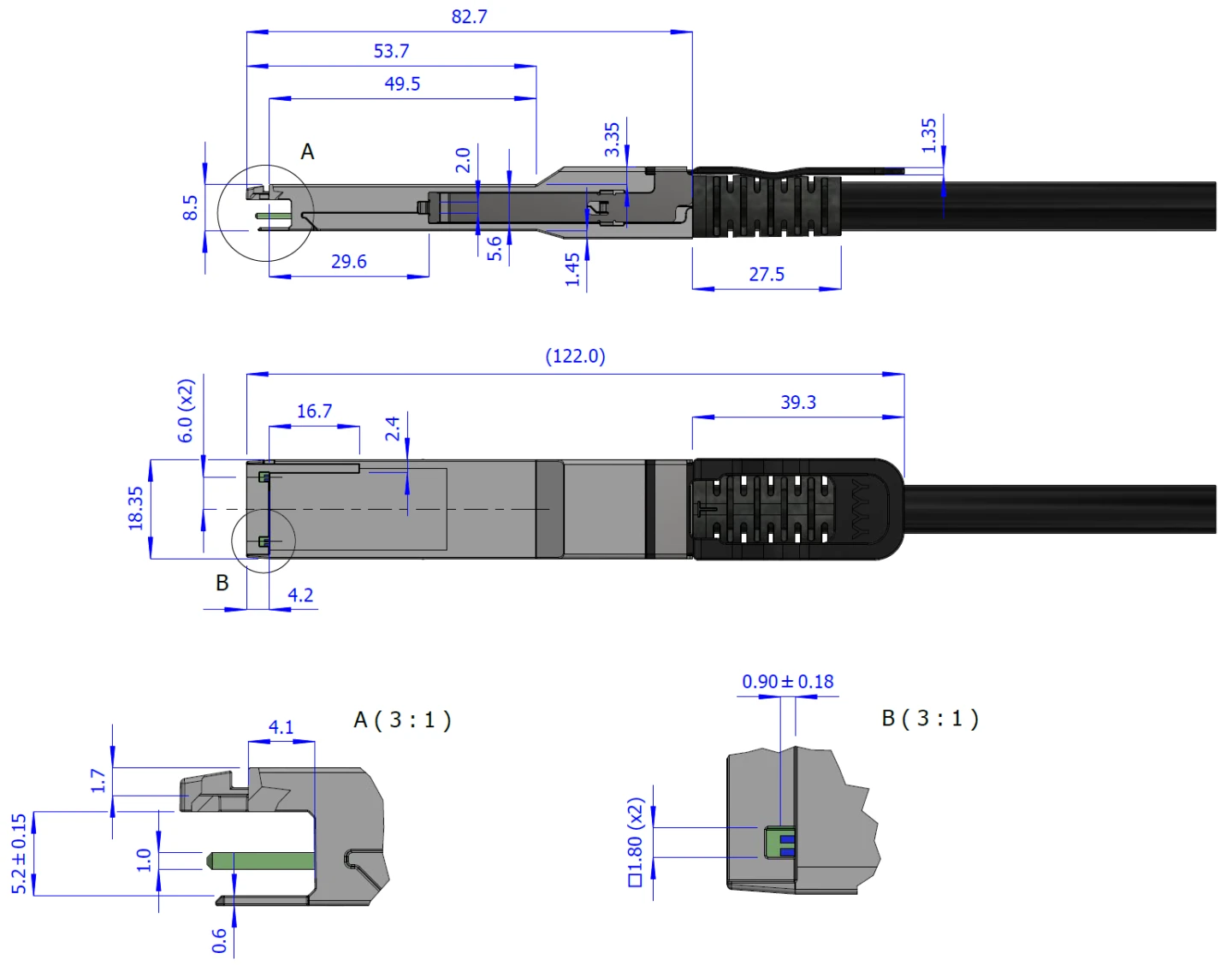
QSFP112 Flat Ends Dimensions
Cable Length Definition (specified in Ordering Information section)

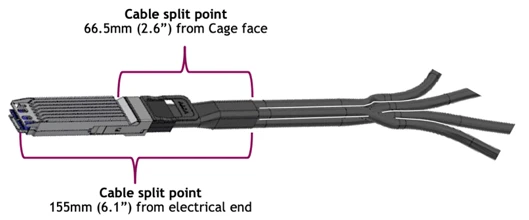
Cable Splitting Point
Backshell Label
The following label is applied on the cable’s backshell. Note that the images are for illustration purposes only. Labels look and placement may vary.
|
OSFP Head |
QSFP112 Ends |

|

(sample illustration) |
Images are for illustration purposes only. Product labels, colors, and form may vary.
Backshell Label Legend
|
Symbol |
Meaning |
Notes |
|
PN – Part Number |
||
|
xx |
Length |
Meters |
|
yy |
Cable gauge |
American wire gauge |
|
SN – Serial Number |
||
|
MN |
Manufacturer name |
2 characters MT |
|
YY |
Year of manufacturing |
2 digits |
|
WW |
Week of manufacturing |
2 digits |
|
MS |
Manufacturer Site |
2 characters |
|
XXXXX |
Serial number |
5 digits for serial number. Reset at start of week to 00001. |
|
Miscellaneous |
||
|
ZZ |
HW and SW revision |
2 alpha-numeric characters |
|
Xm |
Cable length |
Meters |
|
XXAWG |
Cable gauge |
American wire gauge |
|
YYYY-MM-DD |
Year-month-day |
Year 4 digits, month 2 digits, day 2 digits |
|
COO |
Country of origin |
E.g., China |

|
Quick response code |
Serial number |
Cable Jacket Label (Middle of Cable)
The following label is applied on the cable’s jacket at each end. Note that the images are for illustration purposes only. Labels look and placement may vary.

(sample illustration)
The serial number and barcode are for NVIDIA internal use only. Images are for illustration purposes only. Product labels, colors, and form may vary.
Safety: CB, TUV, CE, EAC, UKCA
EMC: CE, FCC, ICES, RCM, VCCI
Ask your NVIDIA FAE for a zip file of the certifications for this product.
This equipment has been tested and found to comply with the limits for a Class A digital device, pursuant to part 15 of the FCC Rules. These limits are designed to provide reasonable protection against harmful interference when the equipment is operated in a commercial environment. This equipment generates, uses, and can radiate radio frequency energy and, if not installed and used in accordance with the instruction manual, may cause harmful interference to radio communications. Operation of this equipment in a residential area is likely to cause harmful interference in which case the user will be required to correct the interference at his own expense.

Handling Precautions and Electrostatic Discharge (ESD)
The cable is compatible with ESD levels in typical data center operating environments and certified in accordance with the standards listed in the Regulatory Compliance Section. The product is shipped with protective caps on its connectors to protect it until the time of installation. In normal handling and operation of high-speed cables and optical transceivers, ESD is of concern during insertion into the QSFP cage of the server/switch. Hence, standard ESD handling precautions must be observed. These include use of grounded wrist/shoe straps and ESD floor wherever a cable/transceiver is extracted/inserted. Electrostatic discharges to the exterior of the host equipment chassis after installation are subject to system level ESD requirements.
Cable Management Guidelines
It is important to follow the instructions and information detailed NVIDIA Cable Management Guidelines and FAQ Application Note to insure proper and optimal installation of this cable and avoid physical damage.