ESF Setup Examples
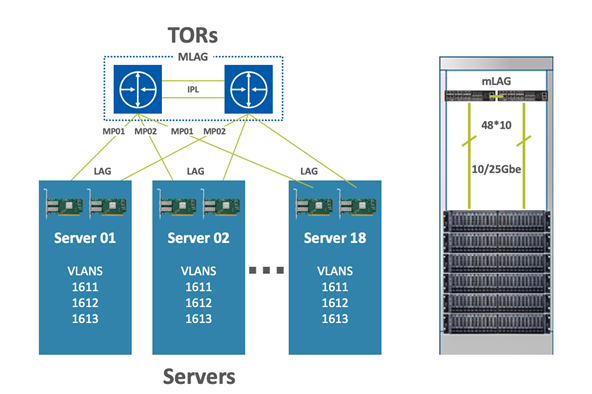
In this setup, we cover the most common deployment scenario and most cost-effective solution: Two switches in a single rack configured with MLAG, providing high availability for the connected servers (as described in the below diagrams).
To leverage the high availability and connectivity to the L3 cloud, Multi-Active Gateway Protocol (MAGP) is used, resolving the default gateway problem when a host is connected to a set of switch routers (SRs) via MLAG with no LACP control (MAGP is a NVIDIA proprietary protocol that implements active-active VRRP). The network functionality in that case requires that each SR is an active default gateway router to the host, thus reducing hops between the SRs and directly forwarding IP traffic to the L3 cloud regardless which SR traffic comes through.
In ESF deployment in a single rack, the ToR switches’ router ports are configured for connectivity with the external network.
To get a detailed overview of the MLAG terminology and its architecture, please refer to the MLAG section in this user manual.
Bill of Materials
As described in the diagram above (two switches in a Rack running MLAG) the fabric in this solution is built with the following components:
|
Component |
Quantity |
Description |
|
Leaf Switch |
2 |
SN2010 Spectrum based 25GbE/100GbE, 1U Open Ethernet Switch with Onyx, 18 SFP28 and 4 QSFP28 ports, 2 Power Supplies (AC), short depth, x86 quad core, P2C airflow, Rail Kit must be purchased separately, RoHS6 |
|
Servers |
Max 18 |
N/A |
|
Uplinks |
2 |
N/A |
|
Network Adapters |
2 per server |
ConnectX-5 Dual-Port SFP28 Port, PCIe 3.0 x16, tall bracket, ROHS R6 |
|
Leaf-Server Cable |
1 per server |
SFP28 25GbE Passive Copper Cable |
|
Leaf-Leaf Cable (IPL) |
2 per rack |
QSFP28 100GbE Passive Copper Cable |
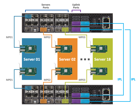
Physical Network Connectivity
The setup connectivity configuration will be as follows:
2 NVIDIA Spectrum SN2010 (used as the TOR switches)
2 X 100GbE uplink ports for the WAN/LAN connectivity (Up to 18 nodes in a rack and a total of 4 x 100GbE uplink ports)
2 X 100GbE ports (on each switch) for switch connectivity (IPL) using 2 X QSFP28 100GbE Passive Copper Cables
Dedicated management port on each switch connected to the Switch Management Network
Single 25GbE connection from the server to each TOR switch by using the SFP28 25GbE Passive Copper Cable
When moving from a single rack deployment into a Leaf-Spine deployment where the ToR switches of each rack are connected to spine switches, there are two major deployment options:
Whole fabric L2 with MLAG configured on the ToR and spine switches, and the Spine switches deploy MAGP.
L2 up to the ToR switches and L3 routing between the ToR and spine switches.
Please refer to the following community post for BGP deployment on top of MLAG in a leaf-spine topology.