Logical Elements
All information provided in a tabular format in UFM web UI can be exported into a CSV file.
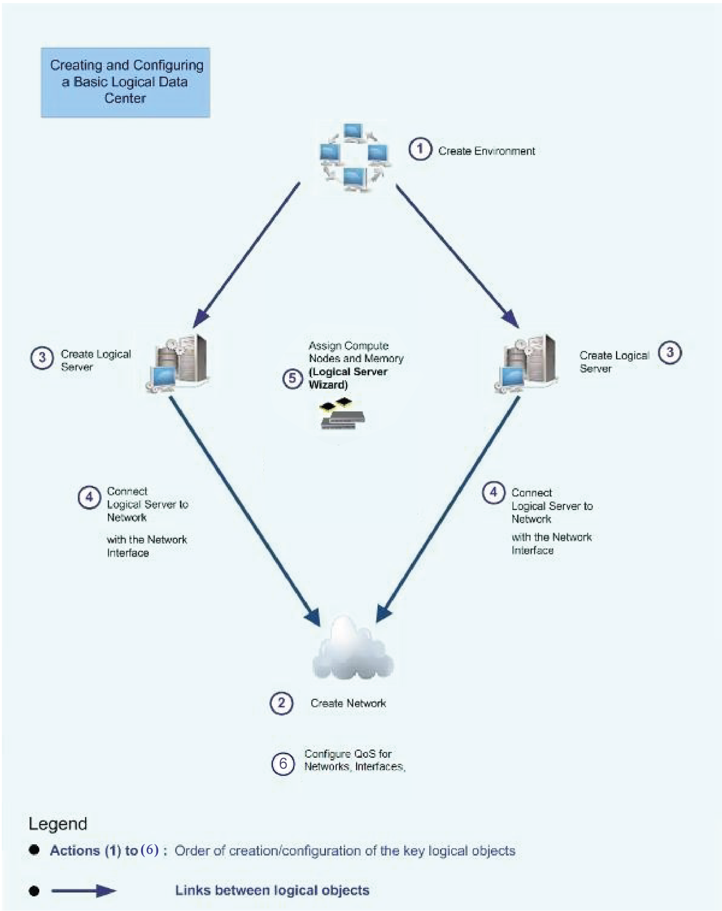
When designing your model, it is recommended to go about it in the following order:
Create an environment.
Create a network.
Create logical servers.
Connect each logical server to a network with a logical server interface.
Assign compute nodes using the Logical Server wizard.
Configure QoS for networks, interfaces.
The following figure represents the design concept:
Logical Elements allows you to:
Manage the fabric according to specific needs (e.g. business needs)
Enable Fabric partitioning and setting QoS policy
Automate configuration and change management
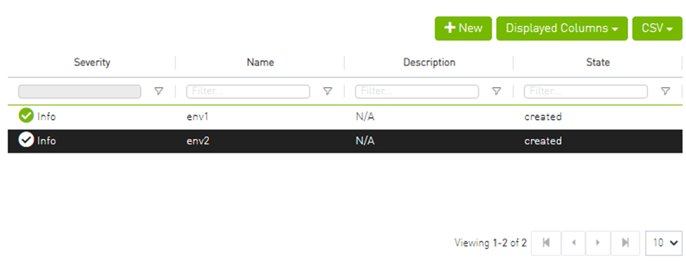
The Environments view allows the user to list/manage all existing environment details (e.g. severity, name, description, state).
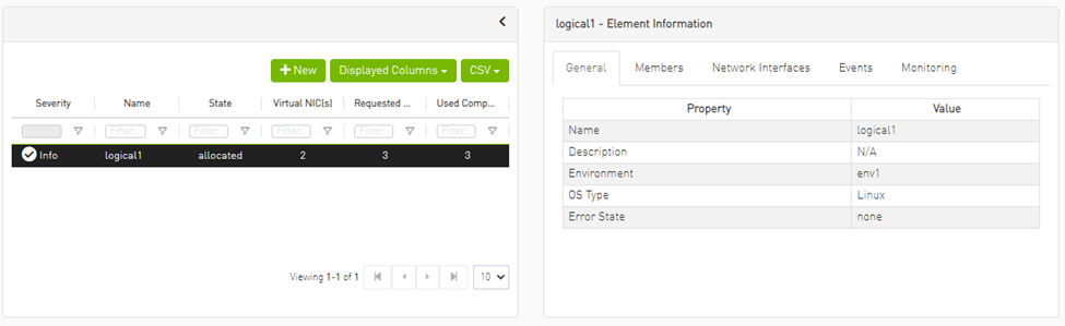
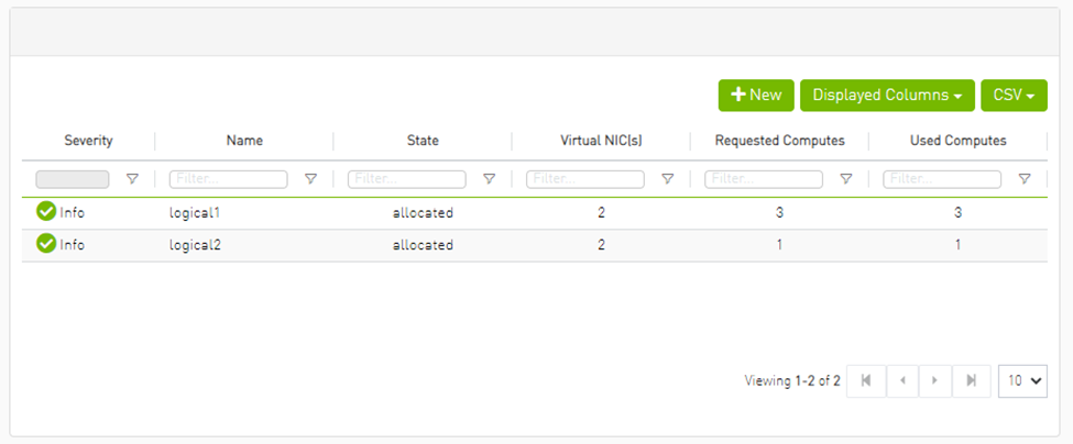
When users select an environment, they are able to show/list the logical server details (e.g. severity, name, state virtual NICs, requested computes, used computes) which exists inside this environment:
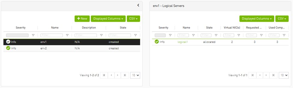
Clicking the logical server name, redirects the user into the logical server view, and the selected logical server is chosen. For more details, please refer to Logical Servers.
Creating New Environment
To create a new environment, click the New button located above the environments table.

Environment’s fields:
In the Name field, enter a name for your new Environment.
Optional: In the Description field, enter a description for your new Environment
Click Submit.
Your new Environment is created. You can see it under the Environments table.
Environment Actions
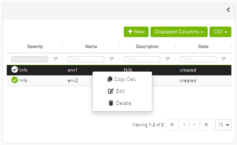
Editing Environments
Click Edit to edit the selected environment.

Deleting Environments
Click Delete to delete the selected environment

The Networks view lists the existing global and local networks and allows managing them.
Adding New Network
This section describes how to create a new global or local network.
When creating a network or network interface, the following SM files are edited as a result of network and network interface configuration:
partitions.conf – the partitions.conf file is changed when a network is created, deleted, or modified.
qos-policy.conf – the qos-policy.conf file is changed when a network, logical server, or network interface is created, deleted or updated.
After creating a network, you may attach it to a logical server, which creates a network interface that enables you to use partitions and configure QoS on logical server members.
To add a new network, click the New button.

The "New Network" window contains four sections presented in the following subsections.
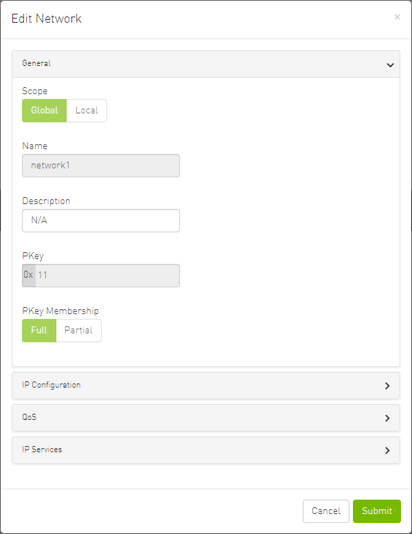
General

This section includes 5 fields:
Scope: Identify the scope of the new network. If "Local" is selected, a new field appears called "Environment" to select which in which environment the new network should be.
Name: Name of the network map (required)
Description: Description of the network map (optional)
Pkey: PKey of the network map (required)
Pkey Membership
IP Configuration
This part is optional.
IP Subnet: Enter the network IP subnet.
WarningUsing class A network addresses (255.0.0.0) for logical networks may cause high memory consumption.
Network Mask: Enter the network mask.
Default Gateway: Enter the network default gateway.

QoS
This part is optional.
UFM allows fabric traffic prioritization by providing four predefined Service Levels (SL). Each SL defines different queuing priority of the traffic in the fabric. The SL is configured centrally and is applied to all fabric ports. Prioritization occurs when traffic with different SL levels is competing for bandwidth on the same port at the same time.
To benefit from QoS capabilities in the fabric, please enable QoS from the Settings page.

QoS is provisioned to the SM via the partitions.conf and qos-policy.conf configuration files. You cannot remove or manually modify these files.
QoS parameters are associated with network interfaces.
The UFM software defines the attributes in the qos-policy.conf file. When each port group is associated with logical server members, a QoS-level is associated with the QoS parameters set, and the matching rule represents the network interface object. The MTU limit is defined for the network object.
A partition is specified by the network. The QoS is generally defined by the network but can be overwritten by the network interface for the specific logical server, providing a more granular definition of QoS for the specified logical server.
Before setting QoS, make sure to select the preferred algorithm. If you do not pre-select the algorithm, UFM automatically applies QoS settings to the default algorithm (MINHOP). For more information about configuring the algorithm, please refer to UFM Routing Protocols.
|
QoS Field |
Description |
|
MTU limit |
The Maximum Transmission Unit (number of bytes) is defined for network object |
|
Service Level |
Select a predefined service level |
|
Rate Limit |
Rate limit in Mbps. This value is converted to a standard InfiniBand enumerator (rate_limit, which has fixed values), and provisioned to the SM via the partitions.conf and qos-policy.conf files. |
IP Services
This part is optional.
UFM allows you to specify one of the following IP distribution (configuration) methods:
Static – UFM Agent creates a new interface with static IP addresses
External – UFM does not create an interface on hosts. Host configuration is user-defined.
This section contains the IP configuration method (i.e. static or external).
The default is external, and it will be disabled in case the IP configuration field is empty


The static IP option reveals 3 fields:
Domain name: the name of the network domain
The Primary DNS and Secondary DNS fields must have a valid IPv4 format
Network Actions
Editing Network
Click Edit to edit the selected network map.
Deleting Network
Click Delete to delete the selected network.

The Logical Server object allows you to define a logical server or cluster, allocate resources, and add network interfaces to connect logical servers to the network (partitioning). The resources automatically allocated by UFM inherit the properties of the network in which they reside. Specific resources may be allocated manually.
Logical server activity can be monitored by activating Logical Server Auditing.
When creating a logical server group:
The UFM server machine cannot be defined as a logical server resource
UFM does not allow the UFM server to be part of central device management actions, such as reboot, shutdown, and software upgrade
The Logical Servers view lists all existing logical server details (e.g severity, name, description, and state) and allows managing them.
Clicking on any logical server opens up an Element Information view with the following tabs:
General
Members
Network Interfaces
Events – the flag ls_monitoring must be enabled to view this tab
Monitoring – the flag ls_monitoring must be enabled to view this tab
Creating New Logical Server
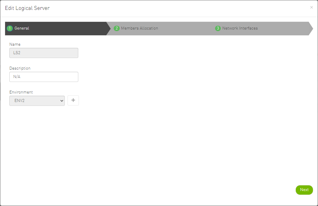
To create a new logical server, click the New button located above the logical server table. A wizard pops open with 3 steps:
General:

Contains three fields:
Name (mandatory): Name of the new logical server
Description (optional): Description of the new logical server
Environment: Select to which environment the new logical server is be added. Clicking the + button by the drop-down menu provides the ability to create a new environment.
- Member Allocation: Contains two methods to allocate members to the new logical server: Manually: Select the members manually from a table view images/networking/download/attachments/111590212/New_Logical_Server_Member_Allocation_Manual.png Automatically: Specify how many members to allocate and member allocation is done automatically images/networking/download/attachments/111590212/New_Logical_Server_Member_Allocation_Auto.png
Network Interfaces:

This allows to bind/link between the new logical server and existing networks.
Clicking the New button above the available networks table allows the user to create a new network.
Clicking the Edit hyperlink, allows the user to edit the selected network.
WarningFor more details, please refer to Networks.
After completing this wizard, click Finish to create the new logical server.
Logical Server Actions
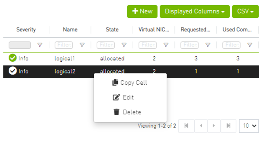
Editing Logical Servers
Click Edit to edit the selected logical server.
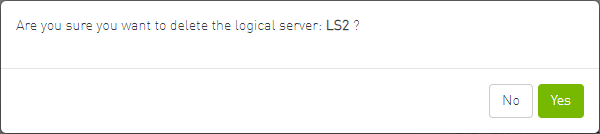
Deleting Logical Servers
Click Delete to delete the logical server.