Supported Interfaces
This section describes the DPU Controller supported interfaces. Each numbered interface referenced in the figures is described in the following table with a link to detailed information.
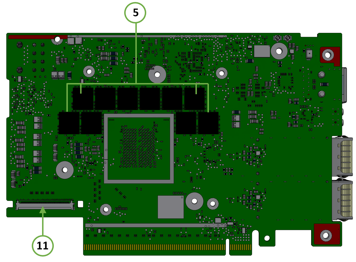
The below figures are for illustration purposes only and might not reflect the current revision of the DPU Controller.
OPN | DPU Controller Component Side | DPU Controller Print Side |
900-9D3C6-00CV-GA0 900-9D3C6-00CV-DA0 | 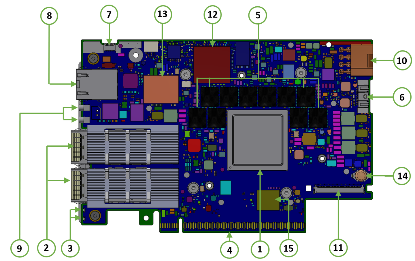
| 
|
Item | Interface | Description |
1 | 16 Arm-Cores SoC | |
2 | The network traffic is transmitted through the DPU Controller QSFP112 connectors. The QSFP112 connectors allow the use of modules and optical and passive cable interconnect solutions | |
3 | One bi-color I/O LEDs per port to indicate link and physical status | |
4 | PCIe Gen 5.0 through an x16 edge connector | |
5 | 20 units of DDR5 SDRAM for a total of 48GB @ 5200MT/s. 128bit + 16bit ECC, solder-down memory | |
6 | NC-SI 20 pins BMC connectivity for remote management | |
7 | Used for OS image loading | |
8 | 1GbE BASE-T OOB management interface | |
9 | Allows PPS IN/OUT | |
10 | An external 12V power connection through an 8-pin ATX connector | |
11 | Two Cabline CA-II plus connectors are populated to allow connectivity to an additional PCIe x16 Auxiliary card | |
12 | DPU BMC | |
13 | 128GB | |
14 | Battery holder for RTC | |
15 | x8 NAND flash |
System-on-Chip (SoC)
NVIDIA BlueField-3 DPU Controller is a family of advanced DPU Controller IC solutions that integrate a coherent mesh of 64-bit Armv8.2+ A78 Hercules cores , an NVIDIA® ConnectX®-7 network adapter front-end, and a PCI Express switch into a single chip. The powerful DPU Controller IC architecture includes an Armv multicore processor array, enabling customers to develop sophisticated applications and highly differentiated feature sets. Leverages the rich Arm software ecosystem and introduces the ability to offload the x86 software stack.
At the heart of BlueField-3, the ConnectX-7 network offload controller with RDMA and RDMA over Converged Ethernet (RoCE) technology delivers cutting-edge performance for networking and storage applications such as NVMe over Fabrics. Advanced features include an embedded virtual switch with programmable access lists (ACLs), transport offloads, and stateless encaps/decaps of NVGRE, VXLAN, and MPLS overlay protocols.
Encryption
DPU Controller addresses the concerns of modern data centers by combining hardware encryption accelerators with embedded software and fully integrated advanced network capabilities, making it an ideal platform for developing proprietary security applications. It enables a distributed security architecture by isolating and protecting each workload and providing flexible control and visibility at the server and workload level; controlling risk at the server access layer builds security into the DNA of the data center and enables prevention, detection, and response to potential threats in real-time. DPU Controller can deliver powerful functionality, including encryption of data-in-motion, bare-metal provisioning, stateful L4 firewall, and more.
Networking Interface
The DPU Controller includes special circuits to protect the card/server from ESD shocks when plugging copper cables.
The network ports are compliant with the InfiniBand Architecture Specification, Release 1.5. InfiniBand traffic is transmitted through the cards' QSFP112 connectors.
Networking Ports LEDs Interface
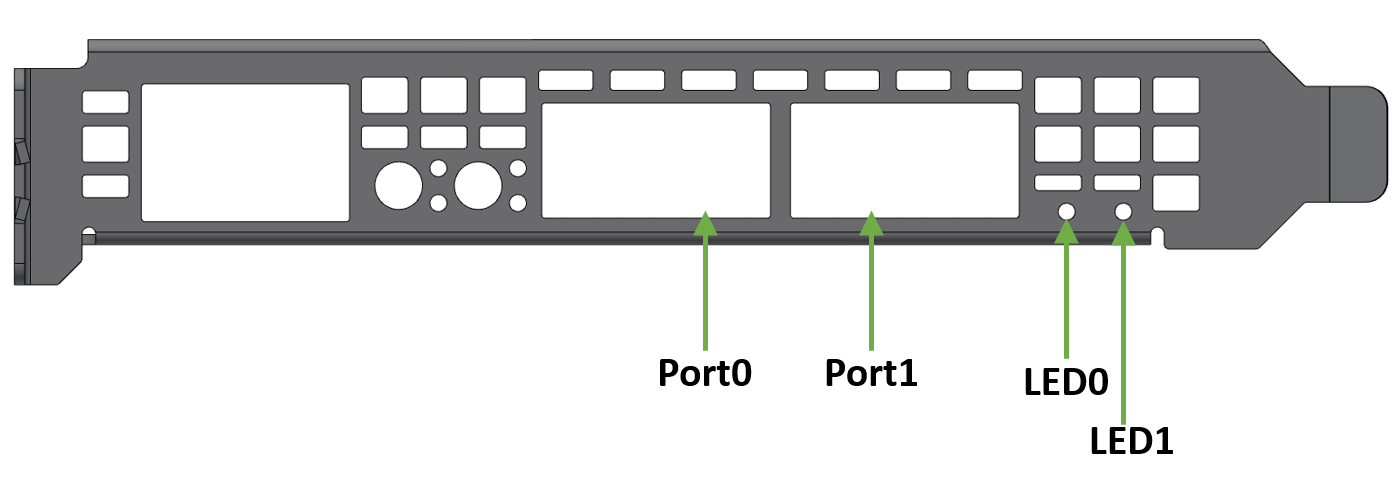
One bicolor (Yellow and Green) I/O LED per port indicates speed and link status.
Link Indications
State | Bi-Color LED (Yellow/Green) | ||||||||||
Beacon command for locating the adapter card | 1Hz blinking Yellow | 
| |||||||||
Error | 4Hz blinking Yellow Indicates an error with the link. The error can be one of the following:
| 
| |||||||||
Physical Activity | Blinking Green | 
| |||||||||
Link Up | Solid Green | 
| |||||||||
Physical Up (InfiniBand Mode Only) | Solid Yellow | 
|
PCI Express Interface
The DPU Controller supports PCI Express Gen 5.0/4.0 through x16 edge connectors. Some cards allow connectivity to an additional PCIe x16 Auxiliary card through the Cabline CA-II Plus connectors.
The following lists PCIe interface features:
PCIe Gen 5.0, 4.0, 3.0, 2.0 and 1.1 compatible
2.5, 5.0, or 8.0, 16.0 or 32.0 GT/s link rate x16 lanes
Auto-negotiates to x16, x8, x4, x2, or x1
DDR5 SDRAM On-Board Memory
The DPU Controllers incorporate 20 units of DDR5 SDRAM for a total of 48GB @ 5200MT/s single or dual channels. 64/128bit + 8bit ECC per channel, solder-down memory.
NC-SI Management Interface
The DPU Controller enables the connection of a Baseboard Management Controller (BMC) to a set of Network Interface Controller (NICs) to enable out-of-band remote manageability. The NC-SI management is supported over RMII and has a connector on the DPU Controller. Please refer to NC-SI Management Interface for pins.
The maximum trace length on the board is 5.7inch.
The USB to UART cable is not used for NC-SI management purposes.
UART Interface Connectivity
The UART debug interface on BlueField-3 boards can be accessed through a 20-pin NC-SI connector, which is associated with the NIC BMC device. The connectivity is shown in the following table:
NC-SI Connector Pin # | Signal on Board |
12 | GND |
14 | UART_TX |
16 | UART_RX |
It is prohibited to connect any RS-232 cable directly! Only TTL 3.3V voltage level cables are supported.
Do not use the USB-to-UART cable for NC-SI management purposes.
USB 4-pin RA Connector
The USB 4-pin RA USB connector is used to load operating system images. Use a 4-pin male connector to a male Type-A cable to connect to the board.

It is prohibited to connect male-to-male to host, it is only used for a disk on key.
The male connector to the male Type-A cable is not included in the shipped DPU Controller card box and should be ordered separately as part of the accessories kit (P/N: MBF35-DKIT).
1GbE OOB Management Interface
The DPU Controller incorporates a 1GbE RJ45 out-of-band port that allows the network operator to establish trust boundaries in accessing the management function to apply it to network resources. It can also be used to ensure management connectivity (including the ability to determine the status of any network component) independent of other in-band network components' status.
For DPU Controllers with integrated BMC: 1GbE OOB Management can be performed via the integrated BMC.
1GbE OOB Management LEDs Interface
Two OOB management LEDs, one Green and one Yellow, behave as described in the table below.
Green LED | Yellow LED | Link/Activity |
OFF | OFF | Link off |
ON | OFF | 1 Gb/s link / No activity |
Blinking | OFF | 1 Gb/s link / Activity (RX,TX) |
OFF | ON | Not supported |
OFF | Blinking | |
ON | ON | |
Blinking | Blinking |
PPS IN/OUT Interface
The DPU Controller incorporates an integrated Hardware Clock (PHC) that allows the DPU Controller to achieve sub-20u Sec accuracy and also offers many timing-related functions such as time-triggered scheduling or time-based SND accelerations (time-based ASAP²). Furthermore, 5T technology enables the software application to transmit fronthaul (ORAN) at high bandwidth. The PTP part supports the subordinate clock, master clock, and boundary clock.
The DPU Controller PTP solution allows you to run any PTP stack on your host.
With respect to testing and measurements, selected NVIDIA DPU Controllers allow you to use the PPS-out signal from the onboard MMCX RA connecter. The DPU Controller also allows measuring PTP in scale with the PPS-In signal. The PTP HW clock on the Network adapter is sampled on each PPS-In signal, and the timestamp is sent to the SW.
External PCIe Power Supply Connector
The external ATX power cable is not supplied with the DPU Controller package; however, this is a standard cable usually available in servers.
To power up the above-mentioned DPUs, it is necessary to use a supplementary 8-pin ATX power cable. Since the power provided by the PCIe golden fingers is limited to 66W, a total maximum of up to 150W is enabled through the ATX 8-pin connector and the PCIe x16 golden fingers.
The maximum power consumption which does not exceed 150W, is in accordance with the mode of operation of the DPU, and is split between the two power sources as follows:
Up to 66W from the PCIe golden fingers (12V)
The rest of the consumed power is drawn from the external PCIe power supply connector
Important Notes and Warnings
The BlueField-3 DPU requires a standard PCIe ATX power connection. However, certain servers may require a custom setup to enable ATX power compatibility.
Consult the manufacturer's manuals and specifications to ensure proper connectivity.
Before connecting the ATX power cable, make sure you are using a PCIe-compliant 8-pin ATX cable from the server power supply kit.
Do not link the CPU power cable to the BlueField-3 DPU PCIe ATX power connector, as their pin configurations differ. Using the CPU power cable in this manner is strictly prohibited and can potentially damage the BlueField-3 DPU. Please refer to External PCIe Power Supply Connector Pins for the external PCIe power supply pins.
Avoid using non-standard cables that do not comply with the DPU, unnecessary adapter cables, or storing the cables near heat sources.
It is preferable that the x16 PCIe golden fingers and the PCI ATX power supply draw from the same power source. For more information on how to power up the card, refer to Power-Up Instructions.
The PCIe ATX 8-pin connector is not compatible with an EPS12V power cable source. Ensure that the appropriate PCIe auxiliary power source is available, not an EPS12V power source.
If you are uncertain about your server's compatibility with the PCI ATX connection, please contact your NVIDIA representative for assistance.
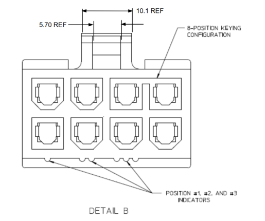
Mechanical Keys of the 8-pin ATX Power Cable (PCIe CEM Specification Rev 5.0)
Cabline CA-II Plus Connectors
The Cabline CA-II connectors on the DPU Controller enable connectivity to an additional PCIe x16 bus in addition to the PCIe x16 bus available through the golden-fingers. The Cabline CA-II Plus connectors allow connectivity to flash cards and NVMe SSD drives.
Specific applications have an interest in direct connectivity to the far end of the Cabline CA-II cables, through the two 60-pin Cabline CA-II connectors, directly to the motherboard, in order to cut the insertion loss and/or the additional space associated with a PCIe x16 Flash Auxiliary Board.
The Cabline CA-II connectors mate with two 60-pin Cabline CA-II cables that can be distinguished by their black or white external insulators and connector pinouts. The black Cabline CA-II cable mates with the DPU Controller's component (top) side, whereas the white Cabline CA-II cable mates with the DPU Controller print (bottom) side. The Cabline CA-II cables are offered in three standard lengths; 150mm and 350mm. For connector pinouts, please refer to Cabline CA-II Plus Connectors Pinouts.
Integrated BMC Interface
The DPU Controller incorporates an onboard integrated NIC BMC and an Ethernet switch. The BMC becomes available once the host server powers up the card. The NIC BMC can control the DPU Controller's power and enables DPU Controller shutdown and power-up.
NVMe SSD Interface
The Self Encrypting Disk (SED) capability is not supported.
The on-board 128GB NVMe SSD is utilized for the storage of user applications and logs. It is important to note that all SSD devices come with a limitation on the total number of write operations they can handle throughout their lifespan. This limit is influenced significantly by the software use case and specific parameters like block size and the pattern of data access (whether it is sequential or random).
It is the customer's responsibility to oversee the rate at which the SSD ages during both the validation of the code and its usage in the field, ensuring that it aligns with the intended use case.
RTC Battery
BlueField-3 incorporates a coin type Lithium battery CR621 for RTC (Real Time Clock).
eMMC Interface
The eMMC is an x8 NAND flash used for Arm boot and operating system storage. Memory size is 128GB, where it is effectively pSLC 40GB.