PCIe Bifurcation Configuration Options
PCIe bifurcation is supported starting from DOCA 2.5 with BlueField BSP 4.5.0 (released December 2023).
NVIDIA BlueField-3 Self-Hosted DPU Controller provides a range of configuration scenarios to meet the demands of environments and deployments. This section describes the various connectivity options for peripherals on the PCIe, such as NVMe SSDs as PCIe endpoints. While this list of scenarios is not exhaustive, it highlights the tested and verified options. Customers seeking to support unlisted configurations should contact NVIDIA Support.
Before setting the desired configuration, take note of the following warnings:
Any customer-set configuration overrides the previous configuration values.
WARNING: Misconfiguration may harm the system.
It is recommended to establish out-of-band connectivity to the BlueField DPU Arm OS before setting any of these configurations for the first time. This enables you to reset the NVConfig parameters to their default values in case of misconfiguration.
The following table summarizes the available configuration scenarios.
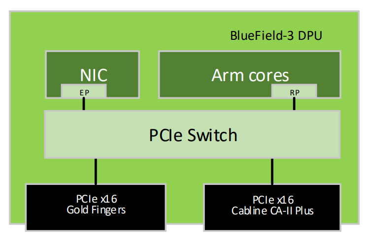
Configuration | Root Port Arm | DPU PCIe Golden Fingers Bifurcation | DPU PCIe Auxiliary Connection Bifurcation |
Default | DPU Arm | 1 x Gen 5.0/4.0 x16 PCIe lanes as down-stream-port | 1 x Gen 5.0/4.0 x16 PCIe lanes as down-stream-port |
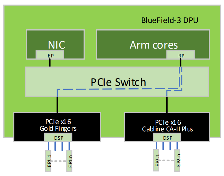
DPU Arm | 4 x Gen 5.0/4.0 x4 PCIe lanes as down-stream-port | 4 x Gen 5.0/4.0 x4 PCIe lanes as down-stream-port | |
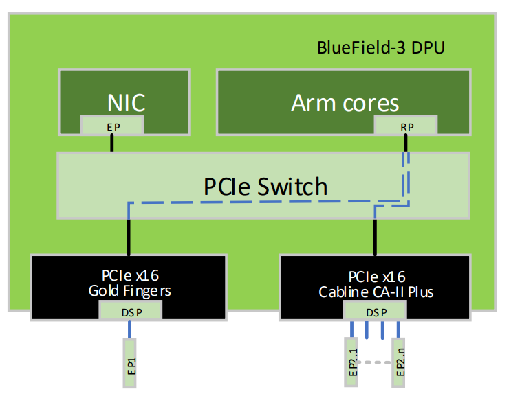
DPU Arm | 1 x Gen 5.0/4.0 x16 PCIe lanes as down-stream-port | 8 x Gen 5.0/4.0 x2 PCIe lanes as down-stream-port |
In this scenario, the x16 PCIe Goldfingers of the BlueField-3 DPU are bifurcated into four PCIe links, where each link comprises x4 PCIe lanes, while the additional x16 PCIe lanes are accessible via the Cabline CA-II Plus connector, bifurcated into four PCIe links, where each link comprises x4 PCIe lanes.
As seen in the below visual representation of this configuration, the DPU’s Arm cores function as Root Port of all devices connected to both the Gold Fingers and the Cabline CA-II Plus connector.
Important Notes:
mlxconfig can be configured either through the host in NIC Mode and DPU Mode, or directly from the DPU’s Arm running OS.
This configuration is persistent even following resets and NIC firmware updates.
The required set of configurations to implement this bifurcation is outlined below.
            mlxconfig -d <device> s PCI_BUS00_HIERARCHY_TYPE=2
mlxconfig -d <device> s PCI_BUS00_WIDTH=3
mlxconfig -d <device> s PCI_BUS00_SPEED=4
mlxconfig -d <device> s PCI_BUS02_HIERARCHY_TYPE=2
mlxconfig -d <device> s PCI_BUS02_WIDTH=3
mlxconfig -d <device> s PCI_BUS02_SPEED=4
mlxconfig -d <device> s PCI_BUS04_HIERARCHY_TYPE=2
mlxconfig -d <device> s PCI_BUS04_WIDTH=3
mlxconfig -d <device> s PCI_BUS04_SPEED=4
mlxconfig -d <device> s PCI_BUS06_HIERARCHY_TYPE=2
mlxconfig -d <device> s PCI_BUS06_WIDTH=3
mlxconfig -d <device> s PCI_BUS06_SPEED=4
mlxconfig -d <device> s PCI_BUS10_HIERARCHY_TYPE=2
mlxconfig -d <device> s PCI_BUS10_WIDTH=3
mlxconfig -d <device> s PCI_BUS10_SPEED=4
mlxconfig -d <device> s PCI_BUS12_HIERARCHY_TYPE=2
mlxconfig -d <device> s PCI_BUS12_WIDTH=3
mlxconfig -d <device> s PCI_BUS12_SPEED=4
mlxconfig -d <device> s PCI_BUS14_HIERARCHY_TYPE=2
mlxconfig -d <device> s PCI_BUS14_WIDTH=3
mlxconfig -d <device> s PCI_BUS14_SPEED=4
mlxconfig -d <device> s PCI_BUS16_HIERARCHY_TYPE=2
mlxconfig -d <device> s PCI_BUS16_WIDTH=3
mlxconfig -d <device> s PCI_BUS16_SPEED=4
In this scenario, the x16 PCIe Goldfingers of the BlueField-3 DPU are bifurcated to one PCIe link with x16 PCIe lanes, while the additional x16 PCIe lanes are accessible via the Cabline CA-II Plus connector, bifurcated into eight PCIe links, where each link comprises x2 PCIe lanes.
As seen in the below visual representation of this configuration, the DPU’s Arm cores function as Root Port of all downstream devices connected to both the Goldfingers and the Cabline CA-II Plus connector.
Important Notes:
mlxconfig can be configured either through the host in NIC Mode and DPU Mode, or directly from the DPU’s Arm running OS.
This configuration is persistent even following resets and NIC firmware updates.
The required set of configurations to implement this bifurcation is outlined below:
            mlxconfig -d <device> s PCI_BUS00_HIERARCHY_TYPE=2
mlxconfig -d <device> s PCI_BUS00_WIDTH=5
mlxconfig -d <device> s PCI_BUS00_SPEED=4
mlxconfig -d <device> s PCI_BUS10_HIERARCHY_TYPE=2
mlxconfig -d <device> s PCI_BUS10_WIDTH=2
mlxconfig -d <device> s PCI_BUS10_SPEED=4
mlxconfig -d <device> s PCI_BUS11_HIERARCHY_TYPE=2
mlxconfig -d <device> s PCI_BUS11_WIDTH=2
mlxconfig -d <device> s PCI_BUS11_SPEED=4
mlxconfig -d <device> s PCI_BUS12_HIERARCHY_TYPE=2
mlxconfig -d <device> s PCI_BUS12_WIDTH=2
mlxconfig -d <device> s PCI_BUS12_SPEED=4
mlxconfig -d <device> s PCI_BUS13_HIERARCHY_TYPE=2
mlxconfig -d <device> s PCI_BUS13_WIDTH=2
mlxconfig -d <device> s PCI_BUS13_SPEED=4
mlxconfig -d <device> s PCI_BUS14_HIERARCHY_TYPE=2
mlxconfig -d <device> s PCI_BUS14_WIDTH=2
mlxconfig -d <device> s PCI_BUS14_SPEED=4
mlxconfig -d <device> s PCI_BUS15_HIERARCHY_TYPE=2
mlxconfig -d <device> s PCI_BUS15_WIDTH=2
mlxconfig -d <device> s PCI_BUS15_SPEED=4
mlxconfig -d <device> s PCI_BUS16_HIERARCHY_TYPE=2
mlxconfig -d <device> s PCI_BUS16_WIDTH=2
mlxconfig -d <device> s PCI_BUS16_SPEED=4
mlxconfig -d <device> s PCI_BUS17_HIERARCHY_TYPE=2
mlxconfig -d <device> s PCI_BUS17_WIDTH=2
mlxconfig -d <device> s PCI_BUS17_SPEED=4