Ethernet VPN (EVPN)
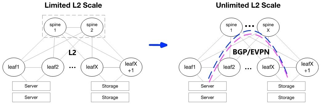
Many data centers today are moving from legacy Layer 2 (L2) designs to modern Layer 3 (L3) web-scale IT architectures. L3 designs simplify troubleshooting, provide clear upgrade strategies, support multi-vendor environments, and dramatically reduce the size of failure domains.
General Data Center Network with EVPN
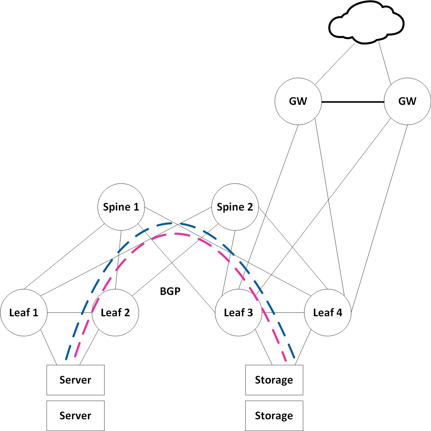
However, many applications and storage appliances still require layer 2 adjacency. VXLAN tunnels can satisfy this L2 adjacency requirement, and EVPN serves as a standard for scale-out L2 Ethernet fabrics. VXLAN can virtualize the data center network, enabling layer 2 segments to be extended over an IP core (the underlay). EVPN is the control plane for modern VXLAN deployments, allowing VTEPs to discover each other via EVPN and exchange reachability information such as MAC and IPs across racks.
ARP suppression is used to reduce the amount of broadcast packets crossing the extended L2 domain. BGP is the underlay routing protocol serving as the transport layer for the overlay VXLAN.
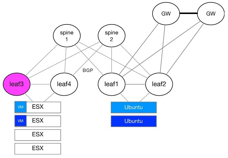
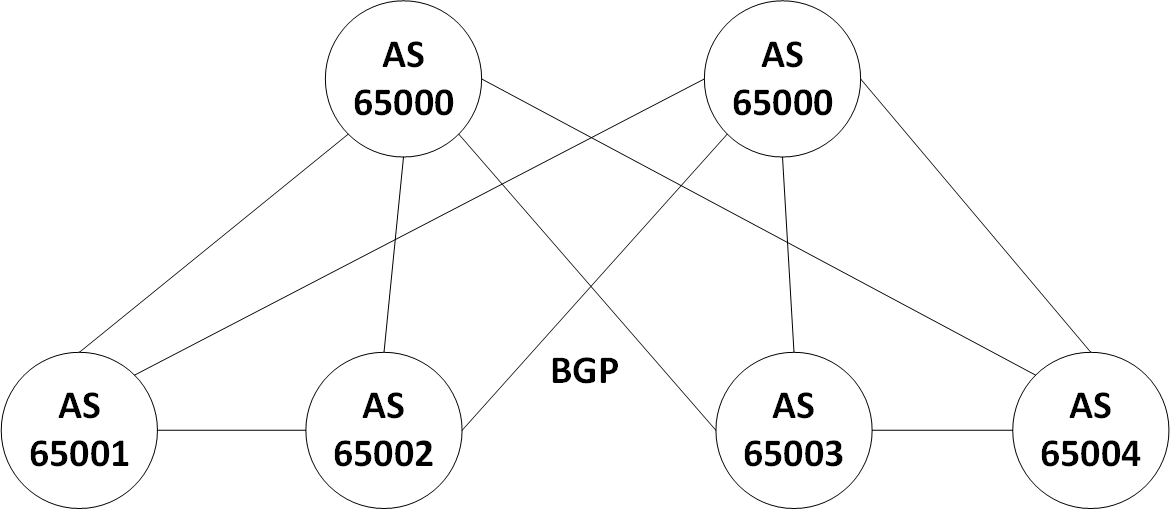
The configuration flow will be described using the setup illustrated below and over leaf3.
Layer 2 Configuration, MLAG, and VLANs
MLAG between leaf3 and leaf4
            lacp
dcb priority-flow-control enable force
protocol mlag
interface port-channel 1
interface ethernet 1/1 channel-group 1 mode active
interface port-channel 1 dcb priority-flow-control mode on force
interface mlag-port-channel 7-8 no shutdown
interface ethernet 1/31 mlag-channel-group 7 mode active
interface ethernet 1/32 mlag-channel-group 8 mode active
vlan 4094
ip routing vrf default
interface vlan 4094
interface vlan 4094 ip address 10.10.10.1/30 primary
interface vlan 4094 mtu 9216
mlag-vip mlag-pair-1 ip 192.168.1.1 /24 force
interface port-channel 1 ipl 1
interface vlan 4094 ipl 1 peer-address 10.10.10.2
no mlag shutdown
Layer 2 Ports
In our setup we use VLAN 6 as the native VLAN, and VLAN 10 as the Tagged VLAN.
We use LACP Bond on our servers, and using them we set LACP on the Switch MPOs.
PXE boot is required to set our MPOs to "lacp-individual enable"
            interface mlag-port-channel 7-8
interface ethernet 1/7 mlag-channel-group 7 mode active
interface ethernet 1/8 mlag-channel-group 8 mode active
interface mlag-port-channel 7-8 mtu 9216 force
interface mlag-port-channel 7 switchport mode hybrid
interface mlag-port-channel 8 switchport mode hybrid
interface mlag-port-channel 7-8 no shutdown
lacp
interface mlag-port-channel 7-8 lacp-individual enable force
vlan 6
vlan 10
interface mlag-port-channel 7 switchport access vlan 6
interface mlag-port-channel 8 switchport access vlan 6
interface mlag-port-channel 7 switchport hybrid allowed-vlan 10
interface mlag-port-channel 8 switchport hybrid allowed-vlan 10
Layer 3 Configuration
Layer 3 Interfaces
Since we use VXLAN, we will set all of our L3 interfaces to support a maximum MTU of 9216. The servers' MTU should be set to below the maximum fabric MTU to allow space for the additional headers of the VXLAN. The VXLAN encapsulation header adds 50 bytes to the overall size of an Ethernet frame.
Router ports serve as uplinks.
Loopback for VTEP source is unique per leaf switch.
            interface ethernet 1/28 no switchport force
interface ethernet 1/29 no switchport force
interface ethernet 1/28 mtu 9216 force
interface ethernet 1/29 mtu 9216 force
interface loopback 1
interface ethernet 1/28 ip address 100.100.100.1/30 primary
interface ethernet 1/29 ip address 100.100.100.5/30 primary
interface loopback 1 ip address 1.1.1.1/32 primary
VXLAN Tunnels Configuration
NVE represents a VTEP. We will use a single VTEP with multiple VNIs.
            protocol nve
interface nve 1
interface nve 1 vxlan source interface loopback 1
interface nve 1 nve controller bgp
interface nve 1 vxlan mlag-tunnel-ip 100.0.0.1
interface nve 1 nve vni 10010 vlan 10
interface nve 1 nve vni 10060 vlan 6
Note that "vxlan mlag-tunnel-ip" is used to configure MLAG with VXLAN. This way other VTEPs will see the MLAG pair as a single entity (for this reason, the "mlag-tunnel-ip" setting should be unique per MLAG pair). As long as the MLAG is up, both switches will use the same IP as the VTEP source. If MLAG state changes to Split Brain (IPL is down but mgmt0 interface is up), the standby switch will use its local loopback for the advertisements; this will prevent impacting traffic from stand-alone ports by the Split Brain scenario.
The only command needed to add more VNIs to a switch is:
interface nve 1 nve vni 10020 vlan 20
ARP Suppression
Traditional L2 network broadcast traffic generated by ARP requests overloads the network. Using ARP suppression with VXLAN enables suppressing these messages at the leaf layer. Let's consider the example setup that is illustrated below.
The support for gratuitous ARP in EVPN has been added, also when ARP Suppression is enabled. The feature allows generating GARP packets on the egress VTEP only when neighbor-suppression is enabled on both VTEPs in the chain (ingress and egress). The suppression should be enabled on interface NVE or on a particular VLAN of the VTEP.
When activating ARP/neighbor suppression, ensure that there is a Switched Virtual Interface (SVI) configured for the VNIs where ARP/neighbor suppression is enabled. It is not necessary for the SVI to have an IPv4 or IPv6 address; it just needs to be present in the configuration and in "admin up" state for the ARP/neighbor suppression feature to function correctly.
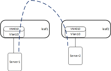
The first time Server2 communicates, it sends an ARP request.
Leaf2 learns its MAC and IP, and sends an EVPN update containing the IP and MAC on the corresponding VNI4010.
Leaf1 learns the IP and MAC of Server2 on VNI4010.
When Server1 sends an ARP request to Server2, leaf1 replies to the ARP request as it has all of the details.
The result is that broadcasts to all leafs that are part of VNI4010 are suppressed.
            interface nve 1 nve neigh-suppression
interface vlan 6
interface vlan 10
EVPN Neighbor-Suppression
|
EVPN neighbor-suppression |
||
|
enabled |
disabled |
|
|
IPv4 Normal ARP |
suppressed |
flooded |
|
IPv4 GARP |
suppressed* |
flooded |
|
IPv6 Neighbor Discovery (equivalent to IPv4 ARP) |
suppressed |
flooded |
|
IPv6 Unsolicited Neighbor Advertisement (equivalent to IPv4 GARP) |
flooded |
flooded |
* the GARP (Gratuitous ARP) packet will reach the destination endpoint despite neighbor suppression
Since IPv4 GARP is processed locally on ingress VTEP and then only BGP update propagated through EVPN network there are several limitations related to scale and performance. The following limitations vary based on the CPU type and current switch load. Switches with higher performance will have better results. Below are the minimum performance expected.
Ingress VTEP: max 1000 frames per second of ingress GARP
Egress VTEP: at least 100 fps for GARP generation
BGP and EVPN Configuration
The examples below use eBGP. Nevertheless, iBGP can be used as well.
Now we will configure our L3 underlay using eBGP as the underlay protocol. The Autonomous System (AS) design that we use as an example represents common designs of eBGP running over leaf/spine data centers. Specifically, each of the leaf switches will be in a separate AS, and the spine layer will be in the same AS layer.
BGP
            protocol bgp
router bgp 65001 vrf default
router bgp 65001 vrf default bgp fast-external-fallover
router bgp 65001 vrf default maximum-paths 32
router bgp 65001 vrf default bestpath as-path multipath-relax force
router bgp 65001 vrf default neighbor 10.10.10.2 remote-as 65002
router bgp 65001 vrf default neighbor 100.100.100.1 remote-as 65000
router bgp 65001 vrf default neighbor 100.100.100.5 remote-as 65000
router bgp 65001 vrf default network 1.1.1.1 /32
router bgp 65001 vrf default network 100.0.0.1 /32
Note: It is necessary to advertise both the local loopback network and the mlag-tunnel-ip network.
EVPN Address Family
In the following code, we create a peer group that contains all of the EVPN configuration and attach it to our L3 interfaces.
            router bgp 65001 vrf default neighbor evpn peer-group
router bgp 65001 vrf default neighbor evpn send-community
router bgp 65001 vrf default neighbor evpn send-community extended
router bgp 65001 vrf default address-family l2vpn-evpn neighbor evpn next-hop-unchanged
router bgp 65001 vrf default address-family l2vpn-evpn neighbor evpn activate
router bgp 65001 vrf default address-family l2vpn-evpn vni auto-create
router bgp 65001 vrf default neighbor 10.10.10.1 peer-group evpn
router bgp 65001 vrf default neighbor 100.100.100.1 peer-group evpn
router bgp 65001 vrf default neighbor 100.100.100.5 peer-group evpn
Spine Configuration
Each spine has a unique loopback address that we use to represent its Router-ID.
            ip routing vrf default
interface ethernet 1/1-1/4 no switchport force
interface ethernet 1/1-1/4 mtu 9216 force
interface loopback 1
interface ethernet 1/1 ip address 100.100.100.2/30 primary
interface ethernet 1/2 ip address 100.100.100.6/30 primary
interface ethernet 1/3 ip address 100.100.100.10/30 primary
interface ethernet 1/4 ip address 100.100.100.14/30 primary
interface loopback 1 ip address 1.1.1.5/32 primary
            protocol bgp
router bgp 65000 vrf default
router bgp 65000 vrf default bgp fast-external-fallover
router bgp 65000 vrf default maximum-paths 32
router bgp 65000 vrf default bestpath as-path multipath-relax force
router bgp 65000 vrf default neighbor 100.100.100.1 remote-as 65001
router bgp 65000 vrf default neighbor 100.100.100.5 remote-as 65002
router bgp 65000 vrf default neighbor 100.100.100.9 remote-as 65003
router bgp 65000 vrf default neighbor 100.100.100.13 remote-as 65004
router bgp 65000 vrf default neighbor evpn peer-group
router bgp 65000 vrf default neighbor evpn send-community
router bgp 65000 vrf default neighbor evpn send-community extended
router bgp 65000 vrf default address-family l2vpn-evpn neighbor evpn next-hop-unchanged
router bgp 65000 vrf default address-family l2vpn-evpn neighbor evpn activate
router bgp 65000 vrf default neighbor 100.100.100.1 peer-group evpn
router bgp 65000 vrf default neighbor 100.100.100.5 peer-group evpn
router bgp 65000 vrf default neighbor 100.100.100.9 peer-group evpn
router bgp 65000 vrf default neighbor 100.100.100.13 peer-group evpn
router bgp 65000 vrf default network 1.1.1.5 /32
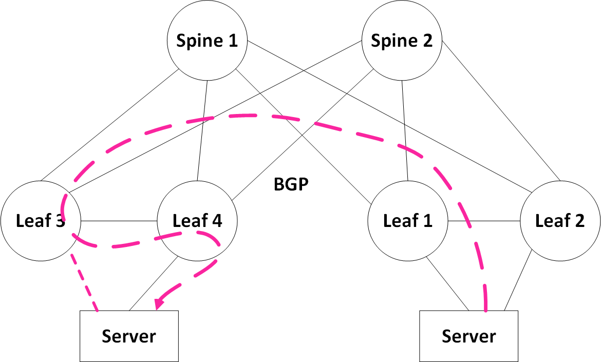
Server Link Failure
Traffic forwarding during a failure follows standard MLAG behavior. If a link of the server fails, traffic will be forwarded across one of the remaining active links.
With reference to the illustration below: If traffic is received on leaf3 due to the ECMP hash of the spine, leaf3 will decapsulate the frame. And based on its local MAC table, leaf3 will also switch the frame across the peer link for forwarding to Server via leaf4.
Uplink Failure
To cover rare cases such as losing all of the uplinks on one of the MLAG peers, we enable BGP over the IPL. This way, traffic coming from the servers towards that leaf can still be routed towards the remote servers.
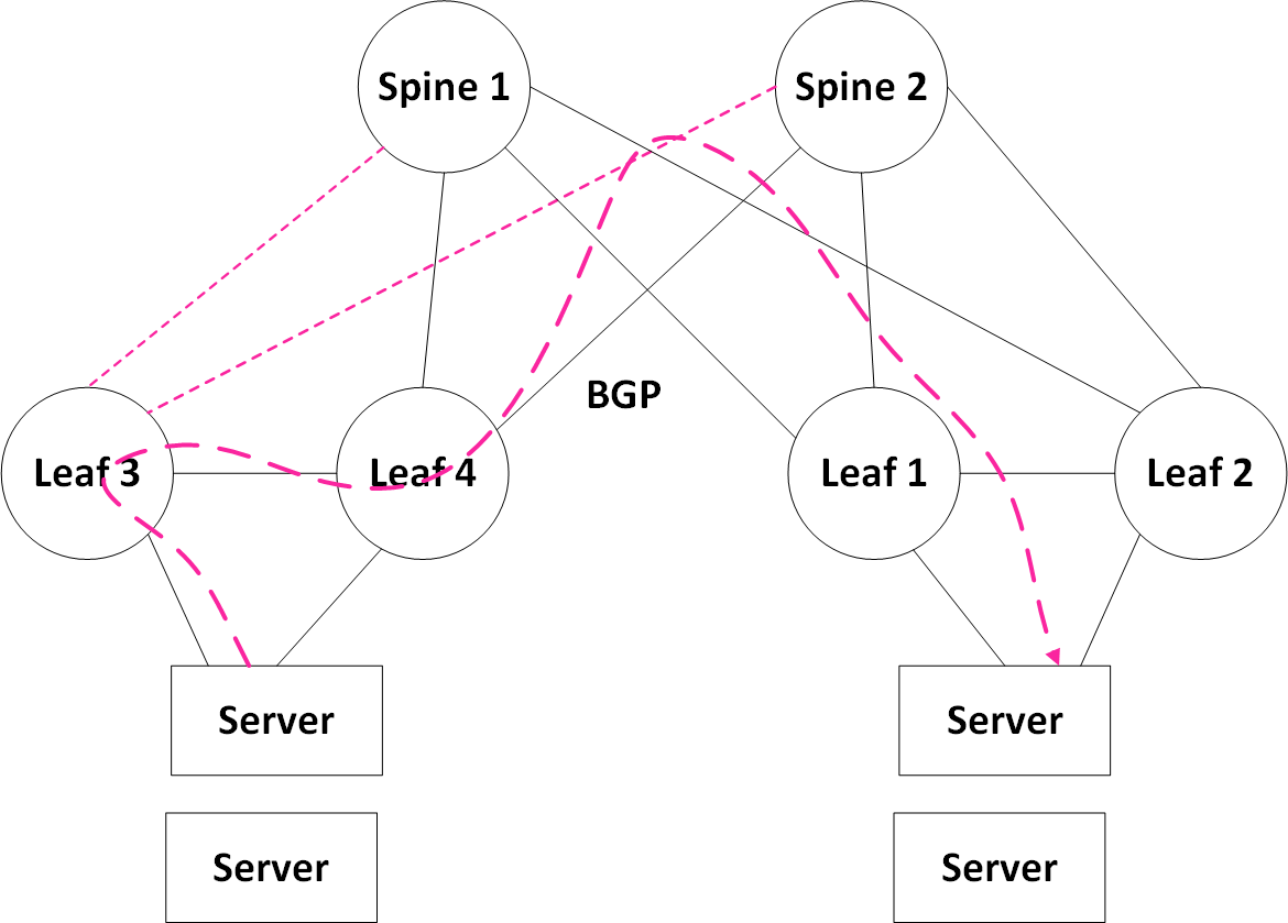
Note: Traffic coming towards the servers connected to leaf4 from the spine will always be terminated on leaf4 and sent directly to the servers without passing over the IPL.
show interface nve 1
Display the configured VTEP on a network device participating in BGP EVPN.
            Interface NVE 1 status:
  Admin state             : Enabled
  Source interface        : loopback 1
  Source interface ip     : 4.4.4.4
  Controller mode         : BGP
  MLAG tunnel ip          : 8.8.8.8
  Effective tunnel ip     : 8.8.8.8
  Global neigh-suppression: Disabled
  Auto-vlan-map           : Enabled
  Auto-vlan-map base      : 100000

  Counters:
    encapsulated (Tx) NVE packets       : 0
    decapsulated (Rx) NVE packets       : 0
    dropped NVE-encapsulated packets    : 0
    NVE-encapsulated packets with errors: 0
show interface nve 1 detail
Display the configured VNIs on a network device participating in BGP EVPN.
            Admin state             : Enabled
Source interface        : loopback 1
Source interface ip     : 4.4.4.4
Controller mode         : BGP
MLAG tunnel ip          : 8.8.8.8
Effective tunnel ip     : 8.8.8.8
Global neigh-suppression: Disabled
Auto-vlan-map           : Enabled
Auto-vlan-map base      : 100000

--------------------------------------------------------------
Vlan         VNI          Neigh Suppression     Mapping type
--------------------------------------------------------------
1            100001       Disabled              Auto
10           10           Disabled              Manual
20           20           Disabled              Manual
30           30           Disabled              Manual
4000         Excluded     N/A                   N/A
show ip bgp evpn summary
Display the BGP peers participating in the layer 2 EVPN address-family and their states.
            VRF name                  : default
BGP router identifier     : 1.1.1.1
local AS number           : 101
BGP table version         : 2176
Main routing table version: 2176
IPV4 Prefixes             : 12
IPV6 Prefixes             : 0
L2VPN EVPN Prefixes       : 9

------------------------------------------------------------------------------------------------------------------
Neighbor          V    AS           MsgRcvd   MsgSent   TblVer    InQ    OutQ   Up/Down       State/PfxRcd
------------------------------------------------------------------------------------------------------------------
10.10.10.2        4    102          2320      2539      2176      0      0      0:00:46:52    ESTABLISHED/5
192.168.14.4      4    104          2112      3159      2176      0      0      0:00:57:56    ESTABLISHED/4
show ip bgp evpn
Display all EVPN routes, both local and remote. The routes displayed here are based on RD as they are across VNIs.
            show ip bgp evpn

------------------------------------------------------------------------------------------------------------------------------------
RD                    Type              Data                   Next Hop         Metric          LocPrf      Weight      Path
------------------------------------------------------------------------------------------------------------------------------------
1.1.1.1:10            mac-ip            00:00:01:11:22:33        1.1.1.1          0              100         0         104 101 ?
9.9.9.9:30            mac-ip            00:10:94:00:00:02        9.9.9.9          0              100         0         104 102 ?
9.9.9.9:30            mac-ip            00:10:94:00:00:03        9.9.9.9          0              100         0         104 102 ?
1.1.1.1:10            imet              1.1.1.1                  1.1.1.1          0              100         0         104 101 ?
3.3.3.3:10            imet              3.3.3.3                  3.3.3.3          0              100         0                 ?
3.3.3.3:30            imet              3.3.3.3                  3.3.3.3          0              100         0                 ?
3.3.3.3:123           imet              3.3.3.3                  3.3.3.3          0              100         0                 ?
9.9.9.9:10            imet              9.9.9.9                  9.9.9.9          0              100         0         104 102 ?
9.9.9.9:30            imet              9.9.9.9                  9.9.9.9          0              100         0         104 102 ?
show ip bgp evpn vni 10060
Display the EVPN information for a specific VNI in detail.
            show ip bgp evpn vni 10060

----------------------------------------------------------------------------------------------------------------------------------------------
RD                    Type              Data                         Next Hop         Metric           LocPrf      Weight         Path
----------------------------------------------------------------------------------------------------------------------------------------------
1.1.1.1:321           mac-ip            00:00:01:11:22:33            1.1.1.1          0                100           0           104 101 ?
1.1.1.1:321           mac-ip            00:10:00:00:00:05            1.1.1.1          0                100           0           104 101 ?
1.1.1.1:321           mac-ip            00:10:33:01:7d:2a            1.1.1.1          0                100           0           104 101 ?
1.1.1.1:321           mac-ip            00:10:66:02:fa:54            1.1.1.1          0                100           0           104 101 ?
1.1.1.1:321           mac-ip            00:10:88:06:a7:33            1.1.1.1          0                100           0           104 101 ?
1.1.1.1:321           mac-ip            00:10:cc:05:f4:a8            1.1.1.1          0                100           0           104 101 ?
9.9.9.9:321           mac-ip            00:10:94:00:00:02            9.9.9.9          0                100           0           104 102 ?
9.9.9.9:321           mac-ip            00:10:94:00:00:03            9.9.9.9          0                100           0           104 102 ?
show ip bgp evpn with multiple filters
Display the EVPN information for a specific VNI in detail, selecting different filters
            switch (config) # show ip bgp evpn vni 1000 route-type mac-ip

---------------------------------------------------------------------------------------------------------------------------------------
RD                    Type              Data                            Next Hop         Metric      LocPrf      Weight      Path
---------------------------------------------------------------------------------------------------------------------------------------
2.3.4.5:5             mac-ip            00:bb:cc:dd:ee:ff               2.3.4.5          0           100         0            ?

switch (config) # show ip bgp evpn vni 1000 route-type mac-ip detail

1 paths for mac-ip 00:bb:cc:dd:ee:ff   Route Distinguisher: 2.3.4.5:5:
  route:
    next hop          : 2.3.4.5
    neighbor ip       : 1.1.1.2
    router id         : 2.3.4.5
    metric            : 0
    weight            : 0
    local pref        : 100
    origin            : incomplete
    Extended Community: 100:268436456(Route-Target-AS)
    Extended Community: tunnelTypeVxlan(TunnelEncap)
    flags             : valid, best
    esi               : 00:00:00:00:00:00:00:00:00:00
    vni               : 1000
    path              :
    ethernet tag id   :
show mac-address-table
Display all local and remote MAC addresses.
            -----------------------------------------------------------
Vlan    Mac Address         Type         Port\Next Hop
-----------------------------------------------------------
10      00:00:01:11:22:33   Static       9.9.9.9(nve1)
10      00:00:01:55:A4:25   Static       1.1.1.1(nve1)
10      00:10:00:00:0A:67   Dynamic      Eth1/10
10      00:10:44:03:51:01   Dynamic      Eth1/10
10      00:10:88:06:A2:02   Dynamic      Eth1/10
10      00:10:AA:07:0F:B1   Dynamic      Eth1/10
30      00:10:00:00:05:29   Dynamic      1.1.1.1(nve1)
30      00:10:00:00:0A:52   Dynamic      1.1.1.1(nve1)
123     00:10:00:00:0A:5B   Dynamic      9.9.9.9(nve1)
123     00:10:44:03:51:0E   Dynamic      9.9.9.9(nve1)
123     00:10:88:06:A2:1C   Dynamic      9.9.9.9(nve1)


Number of unicast(local): 4
Number of NVE:        7
show ip arp
Display all local and remote neighbors (ARP entries), this command is only relevant when arp-suppression is enabled.
             VRF Name default:
 Total number of entries: 13


  ------------------------------------------------------------------------------
  Address              Type            Hardware Address          Interface
  ------------------------------------------------------------------------------
  10.209.20.1          Dynamic ETH     00:00:5E:00:01:01         mgmt0
  10.209.20.57         Dynamic ETH     90:B1:1C:04:11:8D         mgmt0
  10.209.20.58         Dynamic ETH     90:B1:1C:04:11:C1         mgmt0
  10.209.20.67         Dynamic ETH     90:B1:1C:03:57:09         mgmt0
  151.151.10.1         Dynamic ETH     98:03:9B:A2:BF:80         mgmt0
  136.6.166.105        Dynamic ETH     00:00:66:02:FB:0C         vlan 10
  136.6.162.102        Dynamic EVPN    00:00:00:00:05:58         vlan 123
  136.6.162.114        Dynamic EVPN    00:00:01:00:00:02         vlan 123
  172.3.12.4           Static EVPN     00:11:22:33:44:55         vlan 123
  136.6.165.153        Dynamic EVPN    00:00:44:03:51:30         vlan 30
  136.6.166.99         Dynamic EVPN    00:00:01:00:00:02         vlan 30
  204.5.245.253        Dynamic EVPN    00:00:22:01:A8:98         vlan 30
  192.168.34.4         Dynamic ETH     24:8A:07:F4:FF:48         eth 1/15
Layer 2 DCI Connection
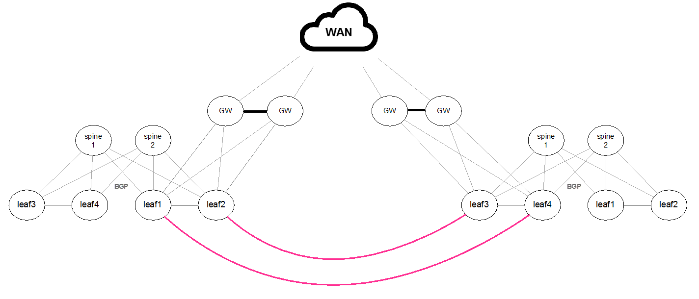
Regular BGP/EVPN Configuration is required since the connection between the sites is L2 based.
Layer 3 Routes WAN
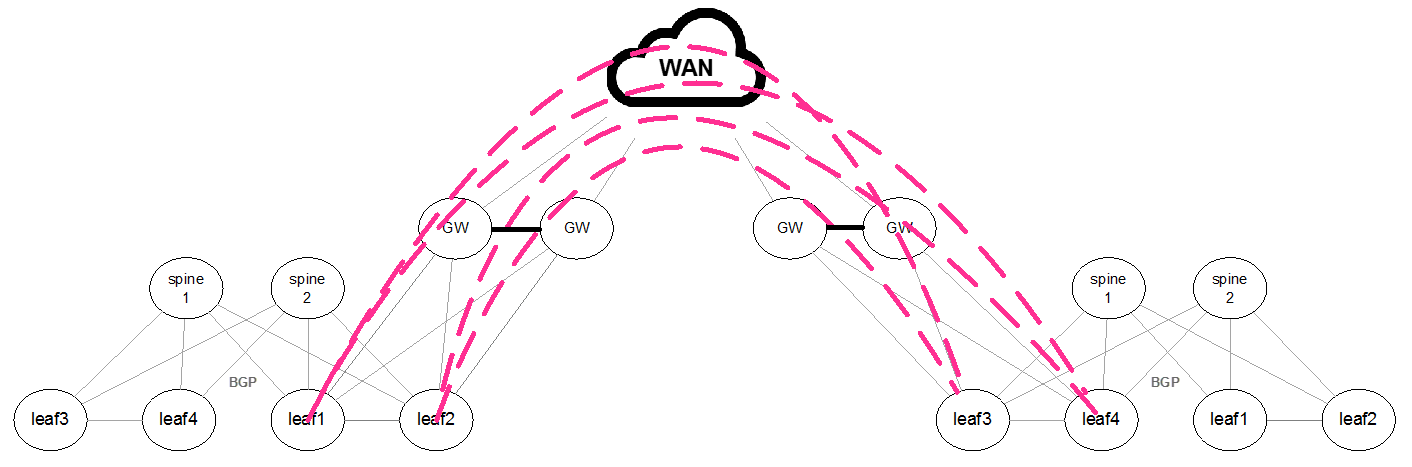
As the WAN transport layer does not support the EVPN/BGP address family, a remote BGP/EVPN connection should be set between each of the local leafs and the remote leafs. To allow this connection BGP should be set to multi-hop mode.
router bgp 65004 neighbor 100.100.100.5 ebgp-multihop 254
In centralized L3 gateway, a specific VTEP can be configured to act as the default gateway for all the hosts in a particular subnet throughout the EVPN network. It is possible to provision an MLAG pair in active-active mode as the default gateway. The VTEP will perform a routing to the destination host together with VxLAN ingress and egress bridging.
Configuration Example of EVPN Centralized Gateway
Run the following:
               ip routing vrf default
   protocol nve
   interface nve 1
   interface nve 1 vxlan source interface loopback 1
   interface nve 1 nve controller bgp
   interface nve 1 nve vni auto-vlan-map base 100000
The underlay
protocol bgp router bgp
1vrfdefaultrouter bgp1vrfdefaultrouter-id200.0.1.1force router bgp1vrfdefaultneighbor1.1.1.2remote-as1router bgp1vrfdefaultaddress-family l2vpn-evpn neighbor1.1.1.2send-community router bgp1vrfdefaultaddress-family l2vpn-evpn neighbor1.1.1.2send-community extended router bgp1vrfdefaultaddress-family l2vpn-evpn neighbor1.1.1.2next-hop-unchanged router bgp1vrfdefaultaddress-family l2vpn-evpn neighbor1.1.1.2activate router bgp1vrfdefaultredistribute connected router bgp1vrfdefaultaddress-family l2vpn-evpn vni auto-createThe overlay
vlan
10interfacevlan10ip address192.168.1.1/24
VTEP Key Outputs
            VTEP1 switch (config) # show ip bgp evpn detail

1 paths for mac-ip b8:59:9f:a7:0f:88 192.168.1.1 Route Distinguisher: 200.0.1.1:10:
  route:
    next hop          : 1.1.1.1
    neighbor ip       : 2.2.2.2
    router id         : 200.0.2.1
    metric            : 0
    weight            : 0
    local pref        : 100
    origin            : incomplete
    Extended Community: 1:269205466(Route-Target-AS)
    Extended Community: tunnelTypeVxlan(TunnelEncap)
    Extended Community: defaultGateway
    flags             : valid, best
    esi               : 00:00:00:00:00:00:00:00:00:00
    vni               : 100010
    path              : 1
    ethernet tag      : 0


VTEP1 switch (config) # show ip arp

Flags:
  G: EVPN Default GW

VRF Name default:
  Total number of entries: 2

  -----------------------------------------------------------------------------------------------
  Address              Type            Flags      Hardware Address          Interface
  -----------------------------------------------------------------------------------------------
  192.168.1.1          Dynamic EVPN    G          B8:59:9F:A7:0F:88         vlan 10
Configuration Example of MLAG EVPN Centralized Gateway
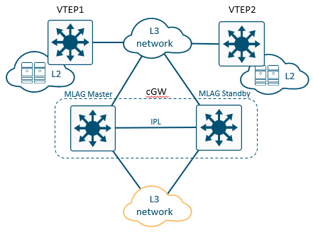
Configure the MLAG Master in the following way
ip routing vrf
defaultprotocol nveinterfacenve1interfacenve1vxlan sourceinterfaceloopback1interfacenve1nve controller bgpinterfacenve1vxlan mlag-tunnel-ip5.5.5.5interfacenve1nve vni auto-vlan-map base100000interfacemlag-port-channel1switchport access vlan10interfacevlan10ip address10.0.0.251/24primaryinterfacevlan4094ip address2.2.2.1/24primary protocol magpinterfacevlan10magp10interfacevlan10magp10ip virtual-router address10.0.0.1interfacevlan10magp10ip virtual-router mac-address00:00:5e:00:00:10mlag-vip MLAG-1ip11.11.11.11/24forceinterfaceport-channel1ipl1interfacevlan4094ipl1peer-address2.2.2.2protocol bgp router bgp1vrfdefaultrouter bgp1router-id200.0.0.1force router bgp1neighbor1.1.1.2remote-as1router bgp1neighbor2.2.2.2remote-as1router bgp1address-family l2vpn-evpn neighbor1.1.1.2send-community router bgp1address-family l2vpn-evpn neighbor2.2.2.2send-community router bgp1address-family l2vpn-evpn neighbor1.1.1.2send-community ext router bgp1address-family l2vpn-evpn neighbor2.2.2.2send-community ext router bgp1address-family l2vpn-evpn neighbor1.1.1.2next-hop-unchanged router bgp1address-family l2vpn-evpn neighbor2.2.2.2next-hop-unchanged router bgp1redistribute connected router bgp1address-family l2vpn-evpn vni auto-createConfigure the MLAG Standby in the following way:
ip routing vrf
defaultprotocol nveinterfacenve1interfacenve1vxlan sourceinterfaceloopback1interfacenve1nve controller bgpinterfacenve1vxlan mlag-tunnel-ip5.5.5.5interfacenve1nve vni auto-vlan-map base100000interfacemlag-port-channel1switchport access vlan10interfacevlan10ip address10.0.0.252/24primaryinterfacevlan4094ip address2.2.2.2/24primary protocol magpinterfacevlan10magp10interfacevlan10magp10ip virtual-router address10.0.0.1interfacevlan10magp10ip virtual-router mac-address00:00:5e:00:00:10mlag-vip MLAG-1ip11.11.11.11/24forceinterfaceport-channel1ipl1interfacevlan4094ipl1peer-address2.2.2.1protocol bgp router bgp1vrfdefaultrouter bgp1router-id200.0.1.1force router bgp1neighbor1.1.1.2remote-as1router bgp1neighbor2.2.2.1remote-as1router bgp1address-family l2vpn-evpn neighbor1.1.1.2send-community router bgp1address-family l2vpn-evpn neighbor2.2.2.1send-community router bgp1address-family l2vpn-evpn neighbor1.1.1.2send-community ext router bgp1address-family l2vpn-evpn neighbor2.2.2.1send-community ext router bgp1address-family l2vpn-evpn neighbor1.1.1.2next-hop-unchanged router bgp1address-family l2vpn-evpn neighbor2.2.2.1next-hop-unchanged router bgp1redistribute connected router bgp1address-family l2vpn-evpn vni auto-create
EVPN MAC Mobility Logs
MAC mobility warning is detected when a MAC address is noticed to move between a local and one or more remote customer site 5 times in a period of 180 seconds. This indicates that multiple hosts have been configured with the same MAC address. The MAC mobility warning is cleared when only one route for the MAC address is left (either local or remote).
When detecting EVPN MAC duplication, the following message will appear:
[metad.WARNING]: EVPN MAC duplication detected for MAC 24:8A:07:A0:B0:0D, IP 2.2.2.2 and VLAN 6 from BGP neighbor 1.1.1.1
A static MAC error is detected when a remote route is received for a MAC address for which a local existing route has been marked as static. The local route being marked as static indicates that the MAC address is not expected to move. In this case, any remote route with this MAC address is an error. The static MAC error is cleared when all remote routes for the MAC address are withdrawn or if the local route is no longer marked as static.
When receiving EVPN MAC mobility route for a static MAC address, the following message will appear:
[metad.WARNING]: EVPN MAC mobility route received for sticky MAC 24:8A:07:A0:B0:0D, IP 2.2.2.2 and VLAN 6 from BGP neighbor 1.1.1.1