TemplateMatching#
Overview#
Template matching is a technique in computer vision used to identify and locate a template image within a larger image. The process involves sliding the template image across the target image and comparing the template to the overlapping image region. It is widely used in various applications, including object detection, image recognition, and tracking. The effectiveness of template matching relies on the choice of matching methods and the characteristics of the images involved.
Reference Implementation#
The reference implementation of this template matching algorithm is based on the NVIDIA VPI (Vision Programming Interface) library. The algorithm computes the normalized cross correlation (NCC) for every possible location of the template inside the source image. The location with the highest score is chosen as the best matching location between source and template image.
The NCC is calculated as follows:
where:
\(T(x′,y′)\) refers to the template image.
\(I(x+x′,y+y′)\) refers to the source image.
\(M(x′,y′)\) refers to the mask.
\(x′\) and \(y′\) are the pixel coordinates inside the template image.
Implementation Details#
Limitations#
The current implementation is optimized for template sizes smaller than 20 x 20. The supported ranges of the template matching parameters are listed as following:
If the input image has a resolution \(W \times H\), then \(W >= 94\) and \(H >= 94\).
If the template image has a resolution \(w \times h\), then \(0 < w <= 31\) and \(0 < h <= 31\).
If the input image has a resolution \(W \times H\) and template image has a resolution \(w \times h\), then the size of the output NCC scores matrix is \((W - w + 1) \times (H - h + 1)\).
Dataflow Configuration#
2 RasterDataflow(RDF) and 1 SequenceDataFlow(SQDF) are needed,
1 input image RDF is used to split the whole image into tiles with size 64x64 and transfer them with halos from DRAM into circular buffer in VMEM.
Template matching is a convolution-like operation. However, the input image and template are top-left aligned instead of center-aligned during the computation.
RDF can only set the halos on both sides in the x or y direction.
When we set halo to (m, n), it will load \(2m\) rows and \(2n\) columns as halo.
But in template matching, if template image has a resolution \(w \times h\), then we need to load \((w - 1)\) columns and \((h - 1)\) rows on the right and down as halo. So we have to pretend that the tile and template of the input image are center-aligned. Since \(haloX = (w - 1) / 2\) and \(haloY = (h - 1) / 2\), template width and height need to be odd numbers.
So when the template width or height is even, we need to redundantly load one more row and one more column. Let’s take 4x4 template as an example. As shown in Figure 1, we need to load 3 columns and 3 rows on the right and down as halo when the template size is 4x4. But we can only set halo to 2. Then we load 4 rows and 4 columns while we only require 3 rows and 3 columns as halo actually.
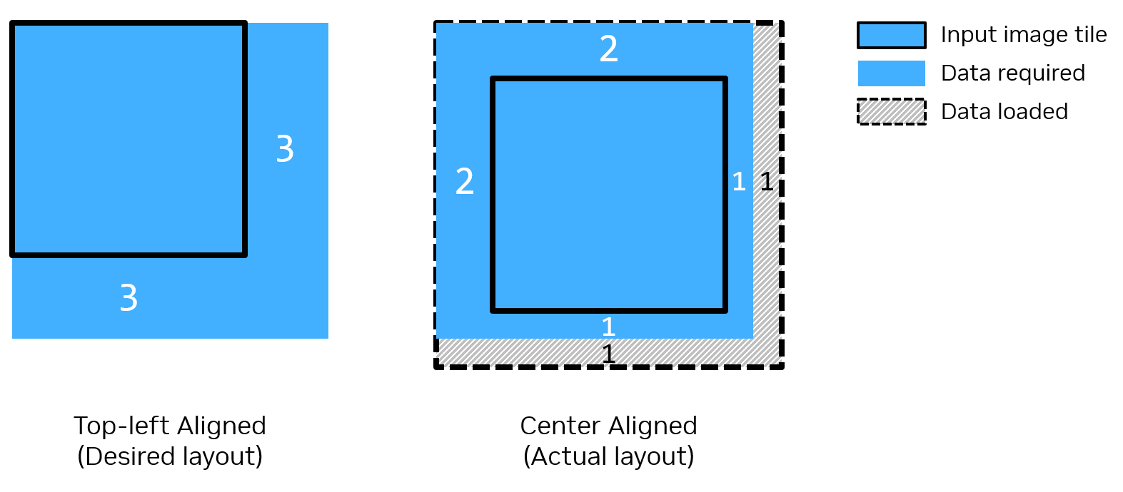
Figure 1: Halo Setting Example of Input Image RDF with Template Size = 4x4#
1 input template SQDF is used to transfer the whole template from DRAM to VMEM one time.
1 output RDF is used to transfer the output NCC scores by tiles from ping pong buffer in VMEM to DRAM.
Buffer Allocation#
5 VMEM buffers are needed,
1 input image buffer with circular buffering for each tile of the input image.
1 input template image buffer with single buffering for the whole template image.
1 intermediate result buffer for the sum of squares of the input image.
1 intermediate result buffer for the sum of squares of the differences between the input image and the template image.
1 output NCC scores buffer with double buffering for each tile of the output NCC scores.
Kernel Implementation#
Our implementation is optimized for small template size.
The input image is Z-scanned in tiles, and tiles are processed using a “ping pong” strategy. The tile size is 64x64. Within each tile, there are two nested loops. The outer loop iterates over each template pixel, while the inner loop processes each tile of the input image in vectors.
Since the input data type is uint8, we store the vector in vcharx vector register.
Thus the vector length is 32.
The template size is an input variable. This means that we cannot know the size of template size at compile time. We can’t unroll loop when we can’t know the loop count at compile time. However, the tile size and vector length is fixed, so we can know the loop count of processing each vector in one tile. That’s the reason we set processing each vector in one tile as the inner loop.
To process each vector, we need to load the input image and template image and calculate the numerator and denominator according to the formula.
Then convert them to float type to calculate division to ensure precision.
This algorithm is a computationally constrained algorithm. Therefore, we need to minimize the number of vector math instructions. We promote while computing to save the number of vector math instructions. At the same time, we split the kernel into two parts and organize the output data using transpose-load instruction and transpose-store instruction instead of vector math instructions.
Specifically, processing each vector are divided into the following two parts:
Compute the numerator and denominator of the formula.
In this part, we need to calculate the numerator and denominator of the formula.
And gradually promote them from uint8 to int32.
For the denominator, we leave the square root operation to the next part. This is because we need the square root operation for floating point types to ensure precision.
Let’s take a 3x3 template as an example. Since the vector length is 32, we process a set of 32 pixels at a time.
First, as shown in Figure 2, the sum of the squares of the first set of 32 pixels is calculated, as well as the sum of the squares of the differences between them and template[0,0].
Then, the second group set of 32 pixels and template[0,1] will also perform the above operation.
Continue this process until the last set of 32 pixels and template[2,2] complete the operation.
The sum of squares of the input image and the sum of squares of the difference are stored in two separate intermediate result buffers.
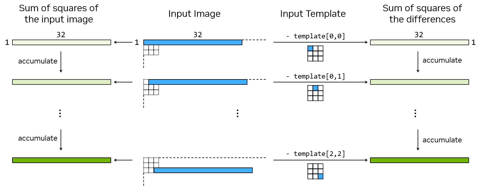
Figure 2: Processing 32 pixels within a tile with the template size = 3x3#
We use vsqsum and dvmaddhw to promote while computing.
As shown in Figure 3, in the first step we use vsqsum to calculate the square of the difference between the input image and the template image.
At the same time, vsqsum can also promote the data from charx type in register v_iput_image and register v_template to shortx type in register dv_sum_difference.
In the second step, we use dvmaddhw to promote the data from shortx in register dv_sum_difference to intx in register dv_sum_difference_lo and register dv_sum_difference_hi.
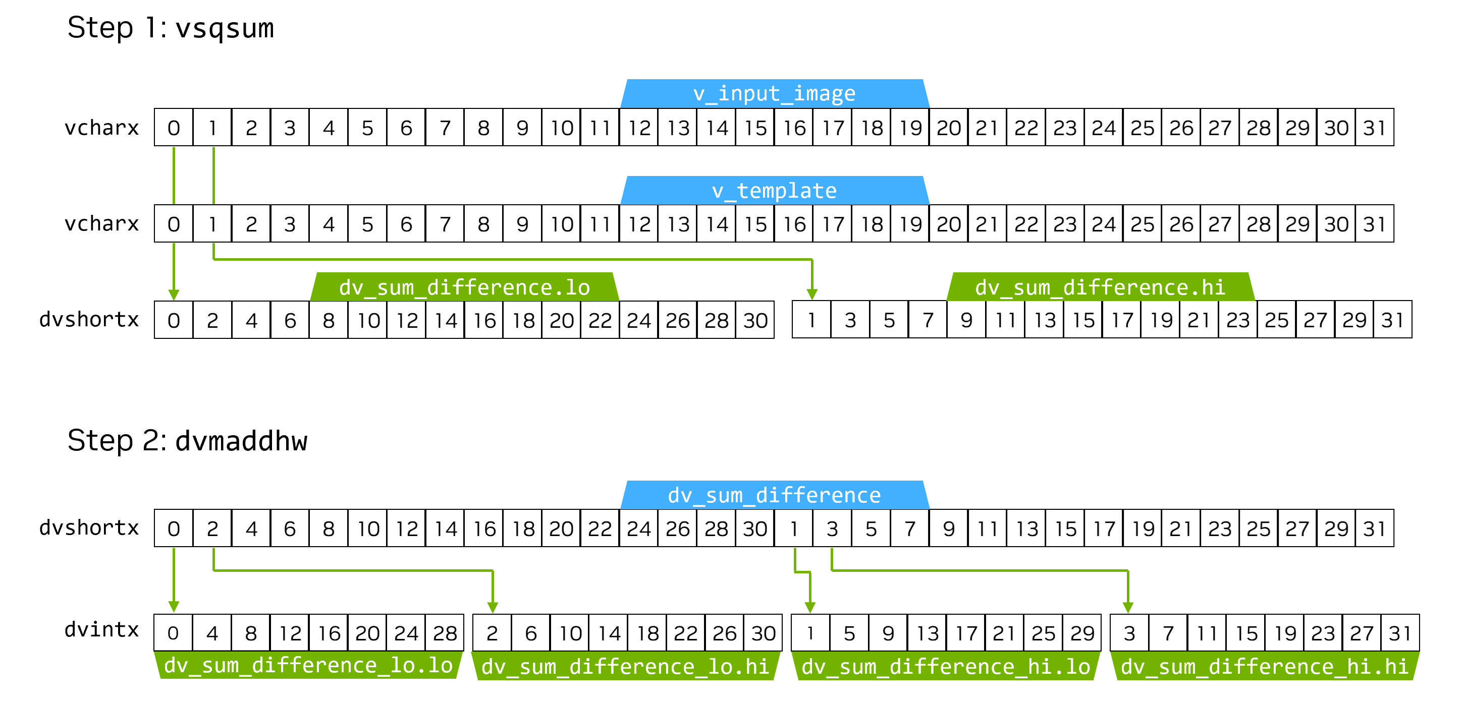
Figure 3: Promotion instructions that cause data interleaving#
It is worth noting that these two promotion instructions cause data interleaving.
The data in the output register should be in the order [0, 1, 2, 3, ... , 31].
But the actual order is: [0, 4, 8, 12, ... , 31].
So we need to reorder the intermediate results.
Reorder the intermediate results and complete the division.
In this part, we need to correct the order of the data, convert them to float, and finally complete the division.
To correct the order of the data, we store the correct order index in a static array.
At each iteration, as shown in Figure 4, we read a column of data from the intermediate result buffer using a transpose-load instruction. Based on the column number, we can generate the correct output address according to the static index array.
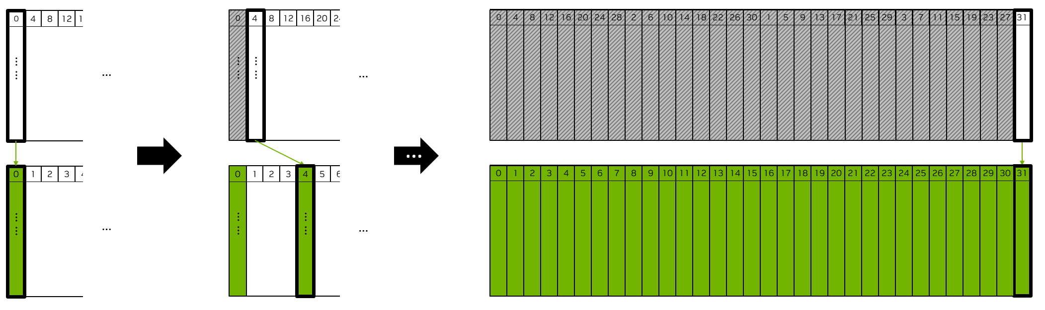
Figure 4: Data reordering method#
After converting them to float and completing the division, we then use the transpose-store instruction to write a column of output NCC scores to the correct location in the output buffer.
Performance#
ImageSize |
DataType |
TemplateSize |
Execution Time |
Submit Latency |
Total Power |
|---|---|---|---|---|---|
1920x1080 |
U8 |
3x3 |
3.021ms |
0.023ms |
12.681W |
1920x1080 |
U8 |
5x5 |
6.409ms |
0.023ms |
11.896W |
1920x1080 |
U8 |
11x11 |
26.729ms |
0.025ms |
12.354W |
For detailed information on interpreting the performance table above and understanding the benchmarking setup, see Performance Benchmark.
Reference#
NVIDIA VPI Documentation: https://docs.nvidia.com/vpi/algo_template_matching.html