Deployment#
This documentation is part of NVIDIA DGX BasePOD: Deployment Guide Featuring NVIDIA DGX A100 Systems.
Deployment of a DGX BasePOD involves pre-setup, deployment, and use of Base Command Manager (BCM) to provision the Kubernetes (K8s) cluster, and optionally deploy Jupyter.
Warning
The # prompt indicates commands that you execute as the root user on a head node. The % prompt indicates commands that you execute within cmsh.
Initial Deployment Steps#
Prepare the infrastructure.
Physical installation should be completed before using this document, along with capturing information about the intended deployment in a site survey. Refer to Site Survey for the example site survey used by this document.
Configure the networking switches.
Refer to Switch Configurations for the example configuration used by this document. Specifics on connecting to and configuring the switches can be found in their associated user guides.
Configure the NFS solution.
As stated in Storage, NFS configuration steps are not in scope for this document.
This DGX BasePOD deployment uses the path /var/nfs/general, which is the NFS export path provided in Table 3 of the Site Survey.
Use the following parameters for the NFS server export file /etc/exports
1/var/nfs/general *(rw,sync,no_root_squash,no_subtree_check)
Set the DGX BIOS so that the DGX systems PXE boot by default. BCM requires DGX systems to PXE boot.
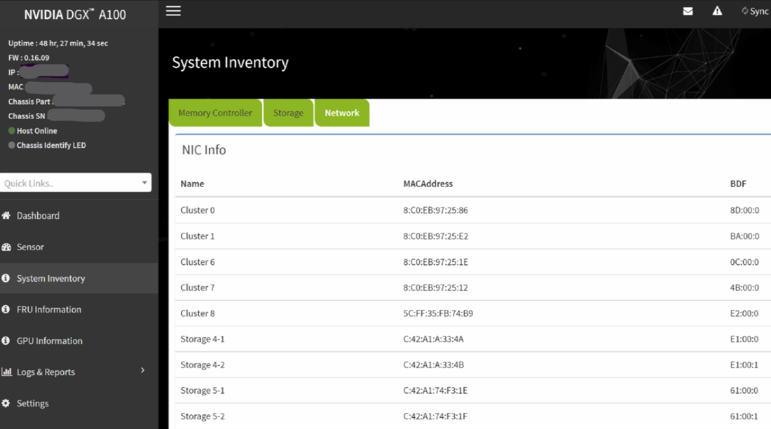
Connect to the BMC of the DGX system.
In the Network tab of the System Inventory window, locate the MAC addresses for the Storage 4-2 and Storage 5-2 interfaces.
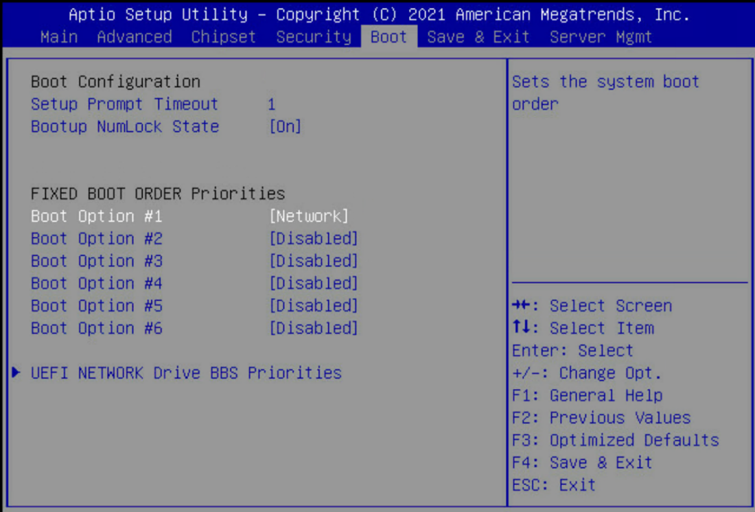
In the DGX A100 system BIOS, configure Boot Option #1 to be [NETWORK]. Set other Boot devices to [DISABLED].
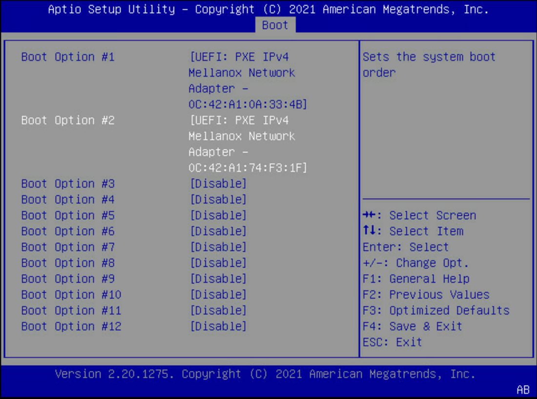
Disable PXE boot devices except for Storage 4-2 and Storage 5-2. Set them to use IPv4.
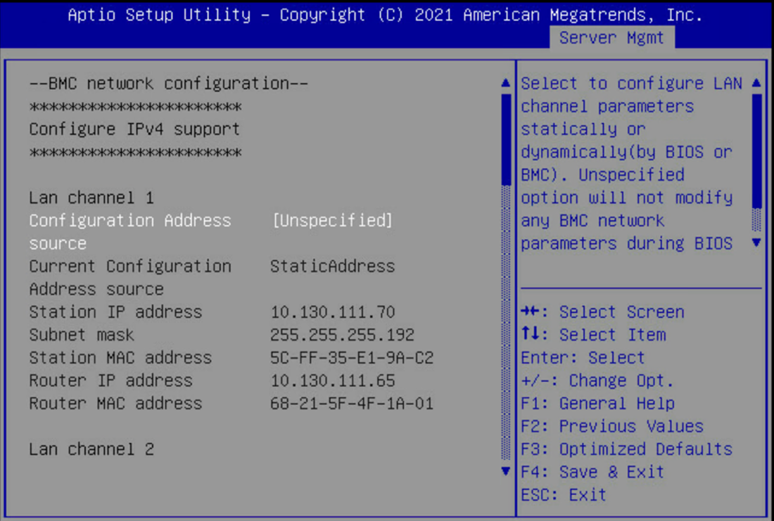
Configure a static IP address for the BMC. Navigate to the Server Mgmt tab of the BIOS, enter the BMC network configuration menu, then set the IPv4 Lan channel 1 Configuration Address Source option to StaticAddress, enter the IP address, subnet, and gateway/router information.
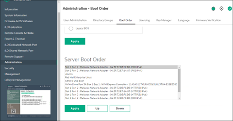
Ensure that the Network boot option is configured as the primary boot option for the K8s control plane nodes that are to be used for this cluster. This is an example of a system that will boot from the network with Slot 1 Port 2 and Slot 2 Port 2.
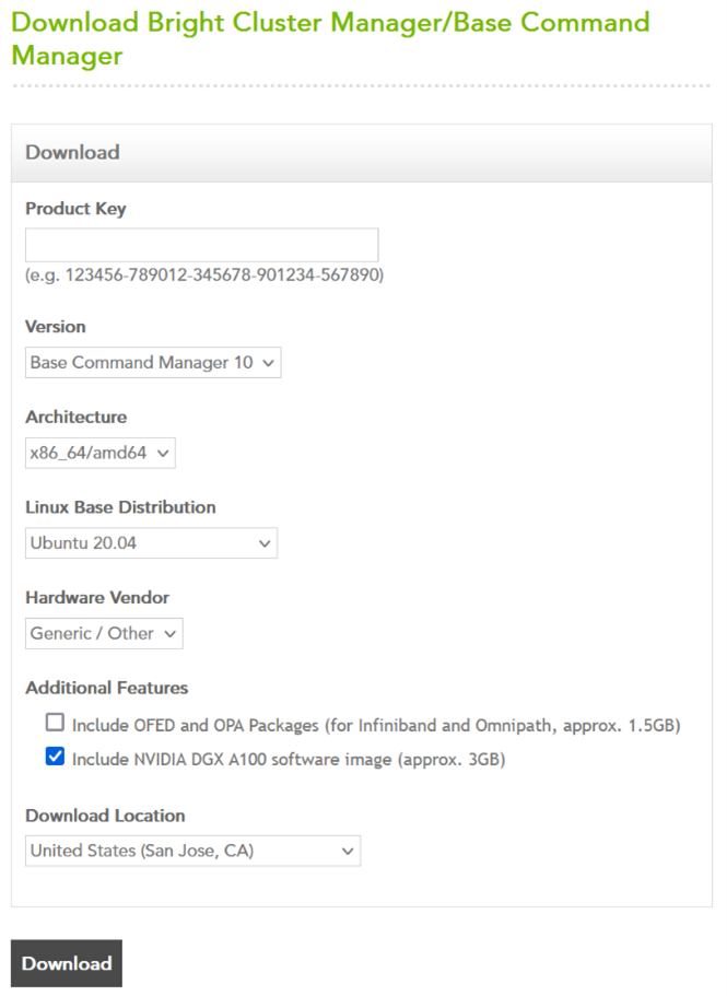
Download a BCM ISO from the Bright Cluster Manager/Base Command Manager download site. Select Base Command Manager 10, Ubuntu 20.04, and check the Include NVIDIA DGX A100 Software image checkbox.
Burn the ISO to a DVD or to a bootable USB device. It can also be mounted as virtual media and installed using the BMC. The specific mechanism for the latter will vary by vendor.
Ensure that the BIOS of the target head node is configured in UEFI mode and that its boot order is configured to boot the media containing the BCM installer image.
Boot the installation media.
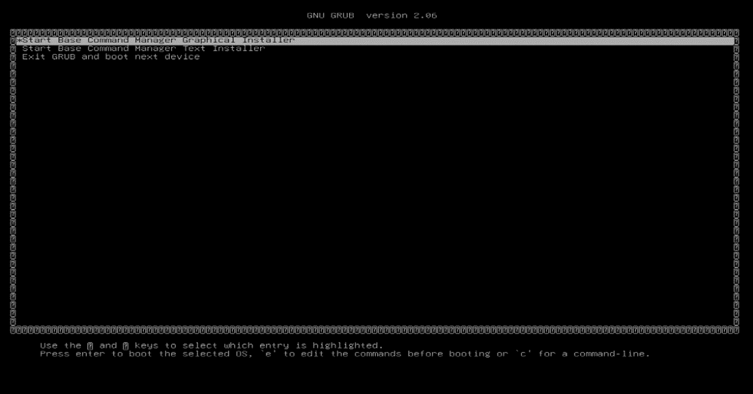
At the grub menu, choose Start Base Command Manager Graphical Installer.
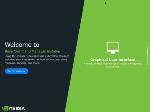
Select Start installation on the splash screen.
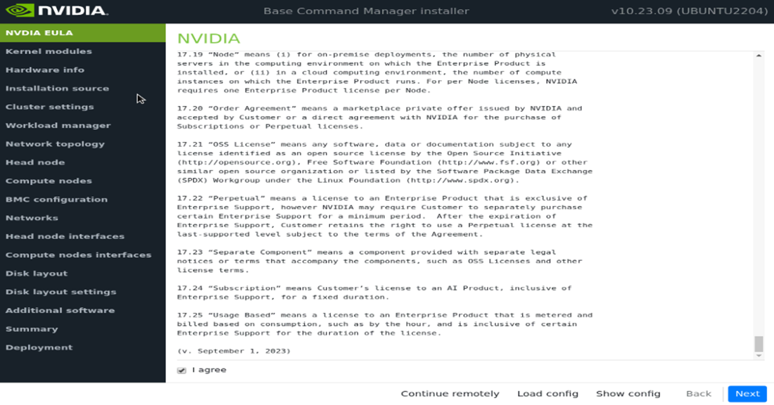
Accept the terms of the NVIDIA EULA by checking I agree and then select Next.
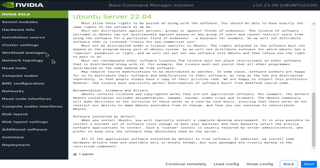
Accept the terms of the Ubuntu Server UELA by checking I agree and then select Next.
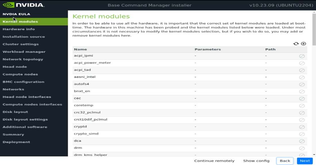
Unless instructed otherwise, select Next without modifying the kernel modules to be loaded at boot time.
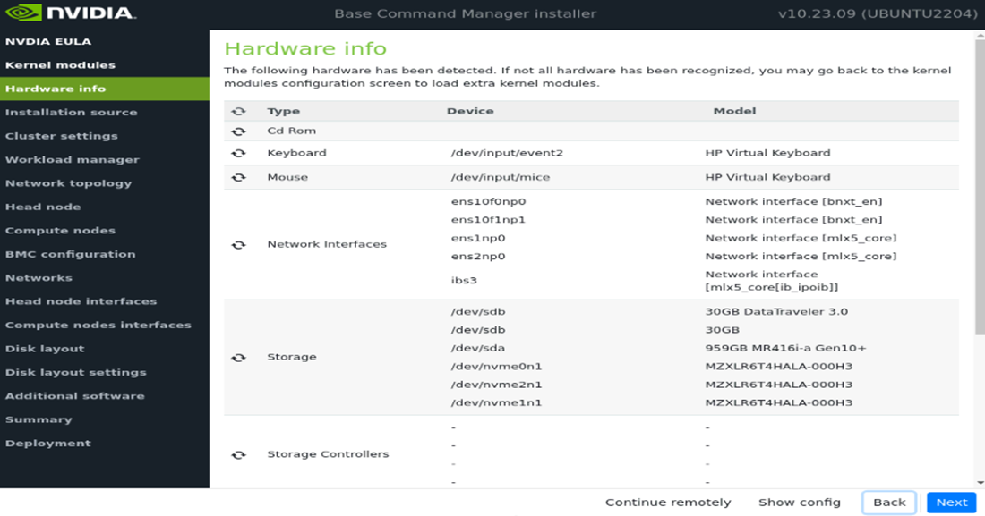
Verify the Hardware info is correct and then select Next. For example, that the target storage device and the cabled host network interfaces are present (in this case three NVMe drives are the target storage device, and ens1np0 and ens2np01 are the cabled host network interfaces).
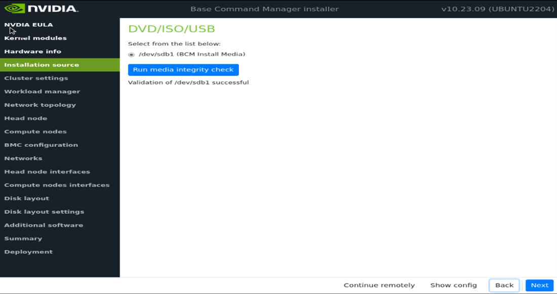
On the Installation source screen, choose the appropriate source and then select Next. Running a media integrity check is optional.
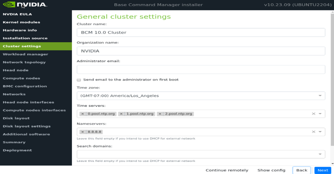
On the Cluster settings screen, enter the required information and then select Next. Enter information from the site survey. An example site survey is in Site Survey.
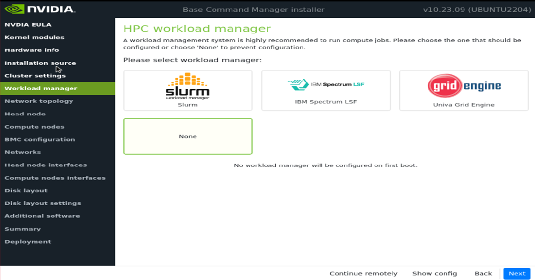
On the Workload manager screen, choose None and then select Next. After head node installation, K8s will be deployed for container orchestration.
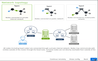
On the Network topology screen, choose the network topology Type 1 and then select Next. In a DGX BasePOD architecture, the cluster nodes are connected to the head node over the internal network, with the head node serving as their default gateway.
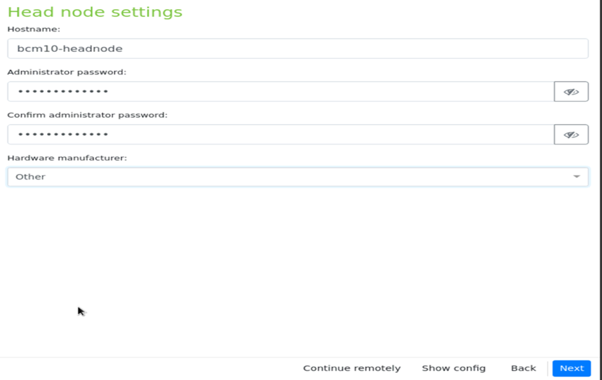
On the Head node screen, enter the Hostname, Administrator password, choose Other for Hardware manufacturer, and then select Next.
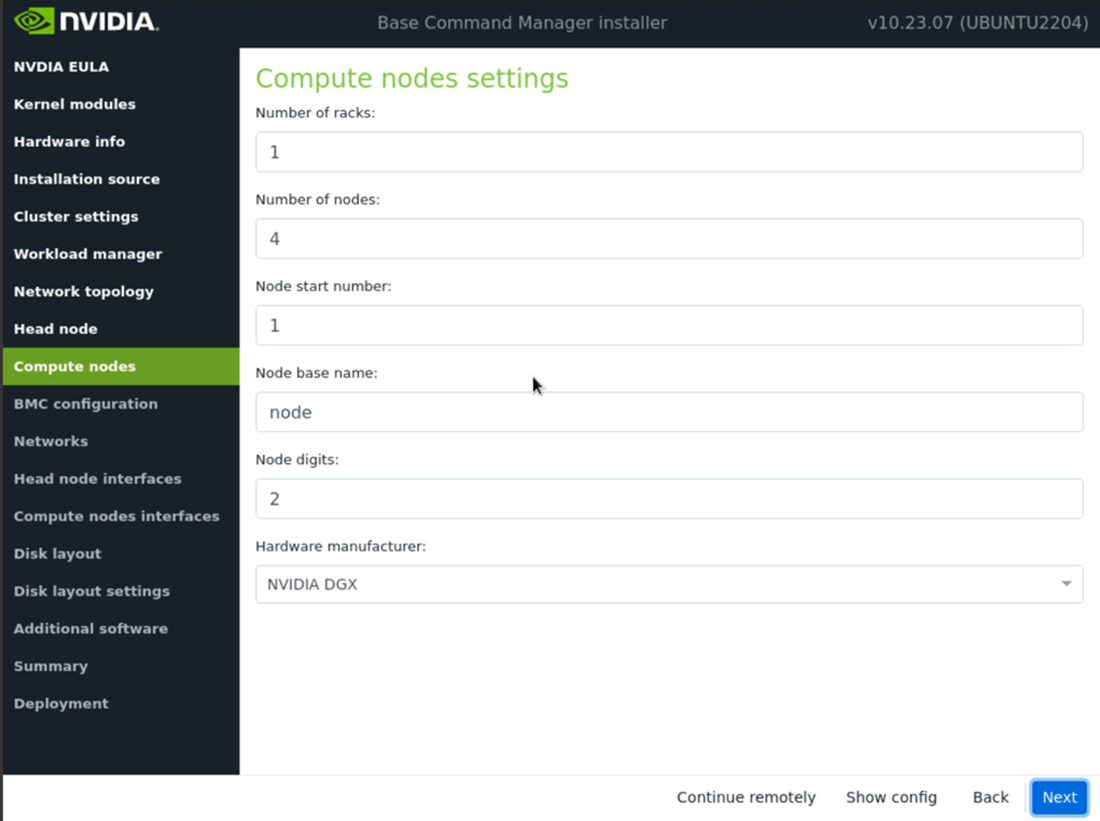
Configure the Compute nodes screen.
Set the Number of nodes to 4.
Set Node digits to 2.
Set Hardware manufacturer to NVIDIA DGX.
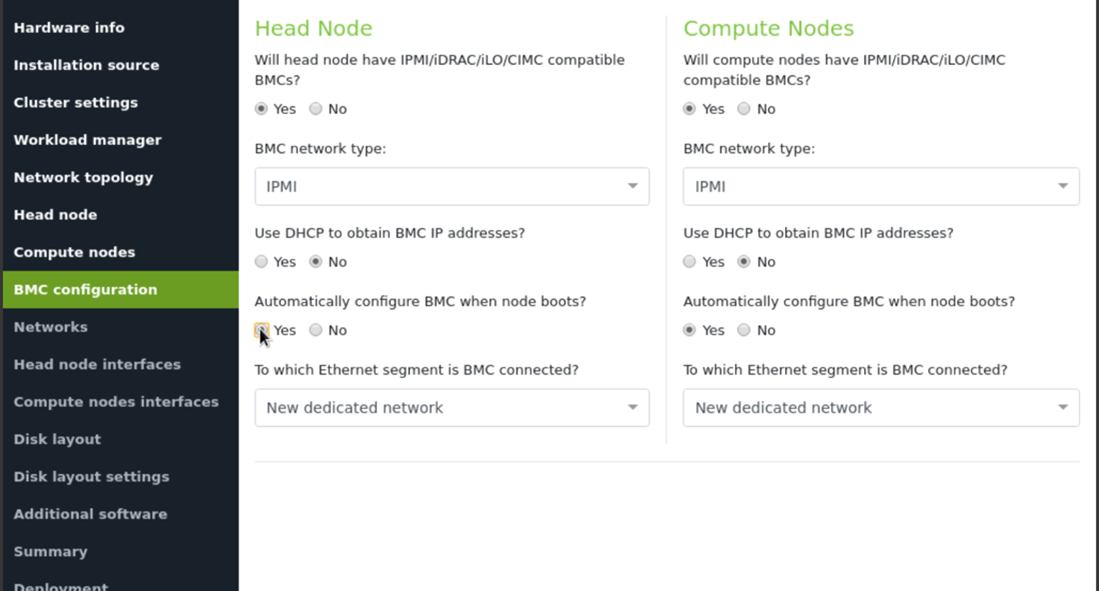
Configure BMC configuration screen.
Select Yes for both the Head Node and the Compute Nodes.
Select IPMI from the BMC network type select lists for both the Head Node and the Compute Nodes.
Select No to the DHCP question for both node types.
Select Yes for Automatically configure BMC when node boots?.
Select New dedicated network from the To which Ethernet segment is BMC connected? list.
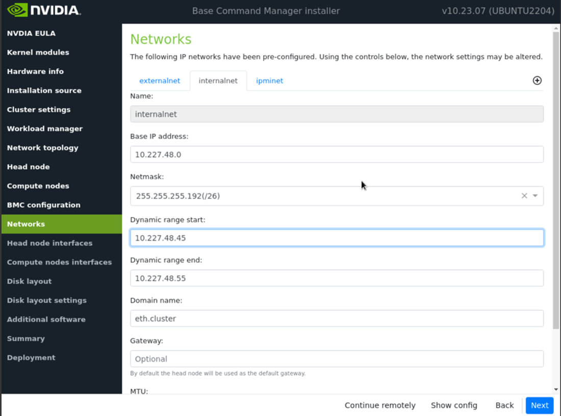
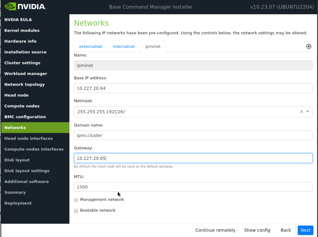
Configure the Networks screens.
externalnet: Set the Base IP address, Netmask, Gateway, and Domain name according to the site survey.
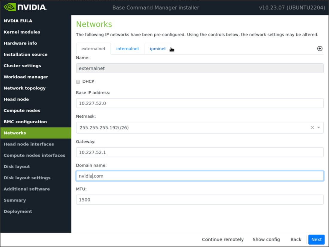
internalnet: Set the Base IP address and Netmask according to the site survey.
ipminet: Set the Base IP address, Netmask, and Gateway according to the site survey.
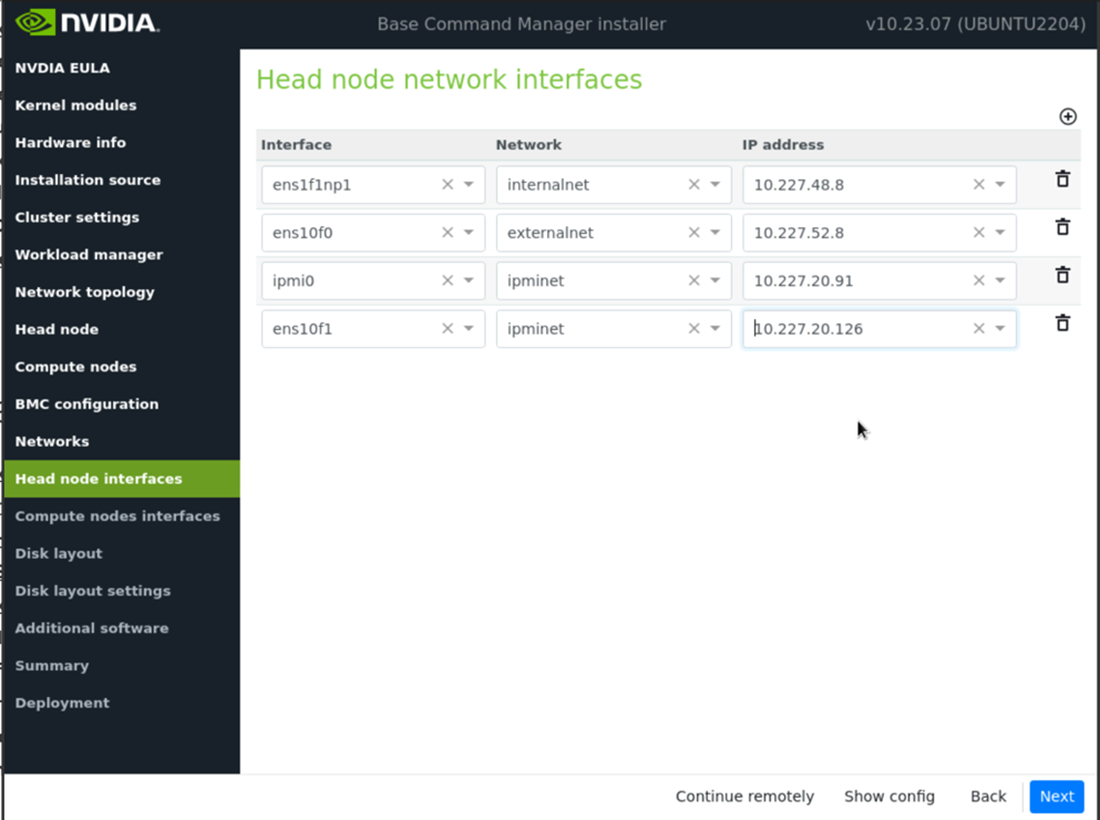
Configure the Head node interfaces according to the site survey and then select Next.
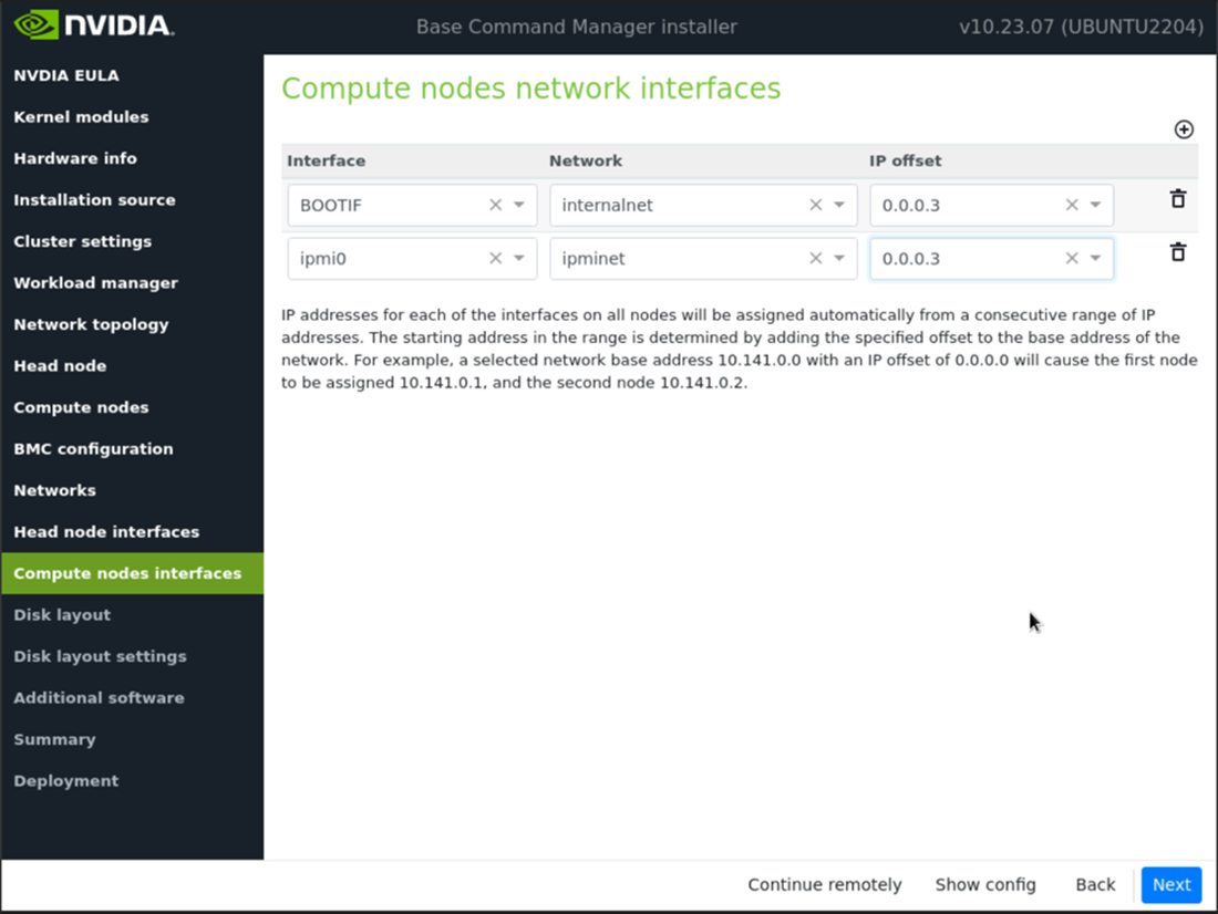
Configure the offset for BOOTIF and ipmi0 to 0.0.0.3 on the Compute nodes network interfaces screen and then select Next.
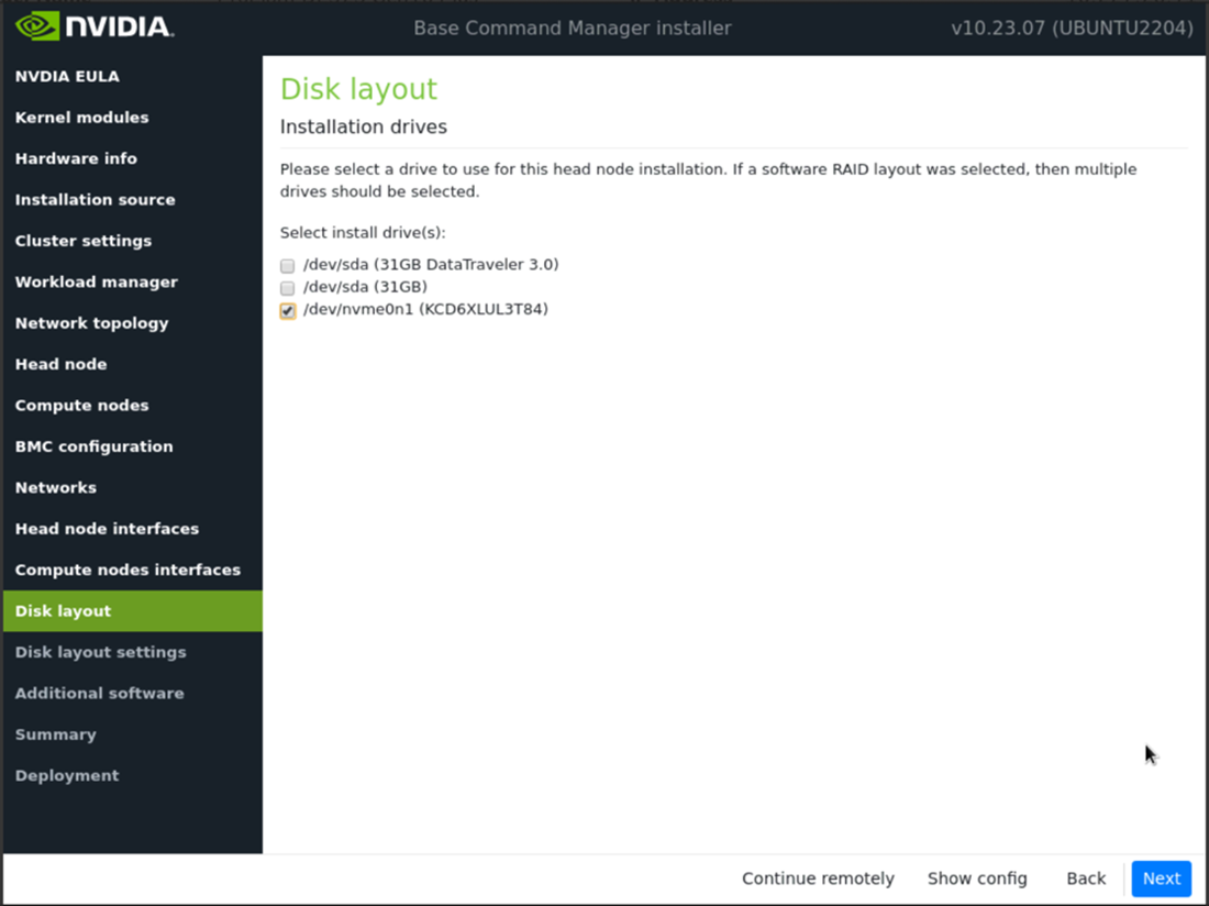
Configure the installation drive(s) on the Disk layout screen and then select Next.
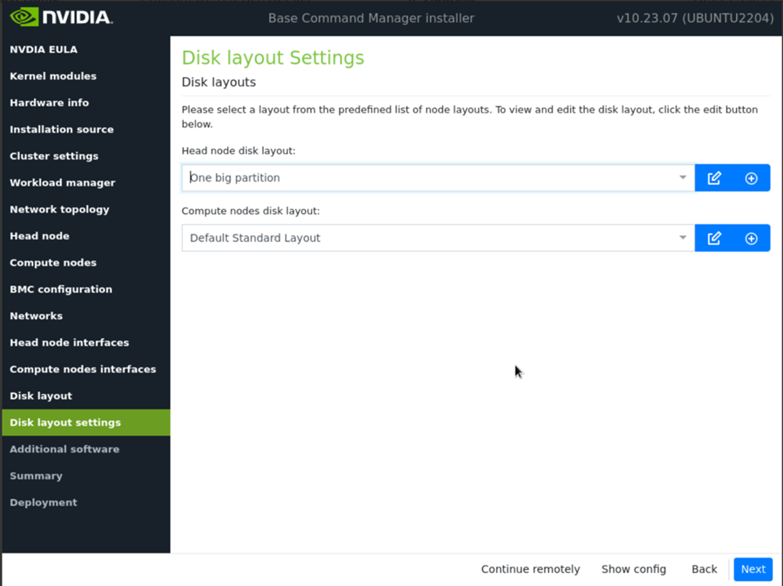
Configure the Disk layout Settings screen and then select Next. Set the Head node disk layout to One big partition and the Compute nodes disk layout to Default Standard Layout.
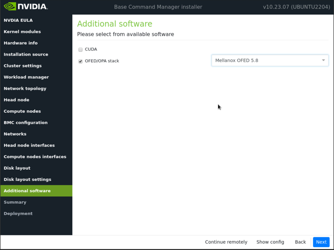
Check the OFED/OPA stack box and choose Mellanox OFED 5.8 on the Additional software screen and then select Next.
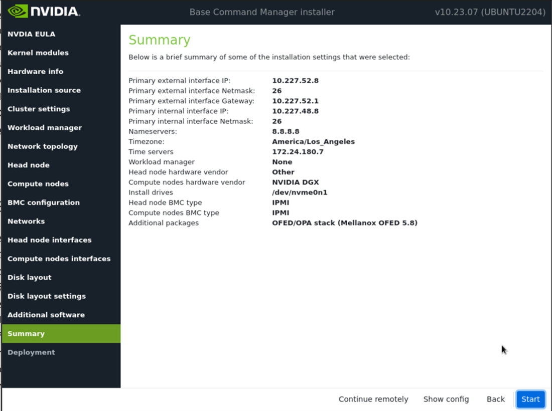
Review the information on the Summary screen. The Summary screen provides an opportunity to confirm the head node and basic cluster configuration before deployment begins. If anything does not match expectations, use the Back button to navigate to the appropriate screen to correct any mistake.
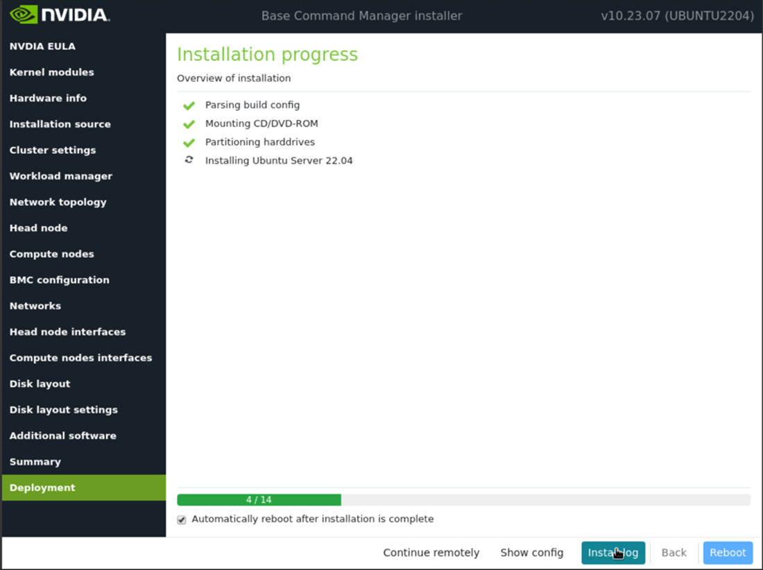
Configure the Deployment screen and then select Reboot. Check the Automatically reboot after installation is complete checkbox to reboot the host upon successful completion of the deployment. Select Install log to see a summary of the installation.
Next Steps#
Use the following documentation to continue your deployment.