Motherboard Tray - Opening and Closing#
You will need to completely remove the motherboard tray from the server to service the following components. If this is the case, refer to the section that describes the procedure for removing the motherboard.
DIMMs (either adding or replacing)
Trusted Platform Module (TPM)
Prepare the Motherboard for Service#
Before pulling the motherboard out of the system, the system must be shut down and cables must be removed from the system.
Caution
Wear an ESD strap during any procedure that involves touching electronic components.
Shut down the system.
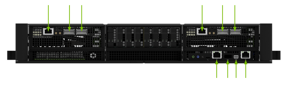
To avoid misconfigurations, label all the cables before unplugging them.
Label all network, monitor, and USB cables.
Use one of the following methods:
Option 1: Standard system
Unplug all power cords.
Option 2: Busbar-based system
De-energize the busbar.
Release the thumbscrews in the ears.
Pull the system out a few inches to disengage it from the busbar.
Unplug all network, monitor, and USB cables.
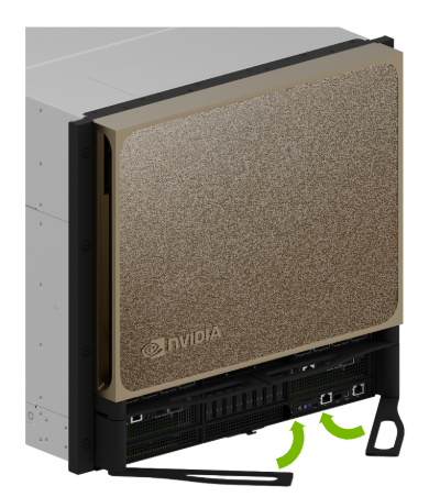
Release the Motherboard#
Unlock the motherboard by pressing the buttons to release the levers from the motherboard.
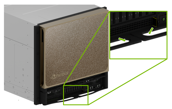
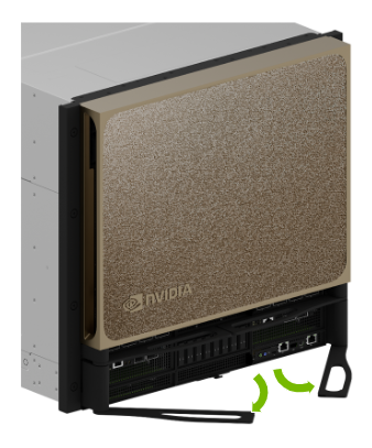
Pull the ejection levers out to disengage the midplane connectors.
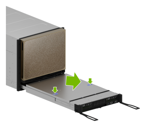
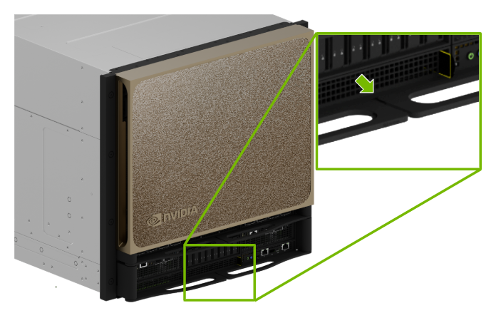
Pull the Motherboard from the Chassis#
Pull the motherboard out until the locking mechanism in the lid engages and prevents further movement.
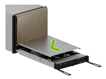
Press down on both buttons and slide the lid back.
Push the lid back and up to remove it.
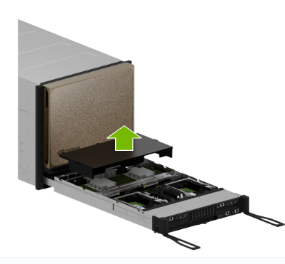
(Optional) Remove the air baffle, if needed.
Install the Motherboard into the Chassis#
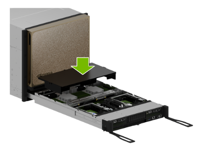
If removed, install the air baffle.
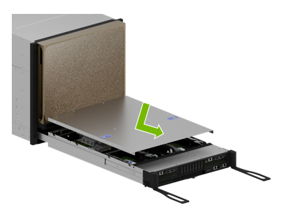
Place the lid on the motherboard and lock it in place by sliding it forward.
Pull back on the blue tabs to release the locking mechanism of the slide rails.

Push the motherboard into the system until the levers engage with the chassis.
Insert the Motherboard#
Lock the ejection levers to engage the backplane connectors.
After the levers are flush against the tray, confirm they lock securely onto the motherboard tray hooks.
Finalize Motherboard Closing#
Use the labels on the cables to reconnect them to the correct ports.
Use one of the following methods:
Option 1: Standard system
Connect all power cords.
Option 2: Busbar-based system
Re-energize the busbar.
Push the system back to engage with the busbar.
Tighten the thumbscrews in the ears to secure the system.
Power on the system.