Hardware Layout#
Note
For the detailed specification of each connector, header and carrier board, please refer to the NVIDIA Jetson AGX Thor Developer Kit Carrier Board Specification.
IO Side Layout#
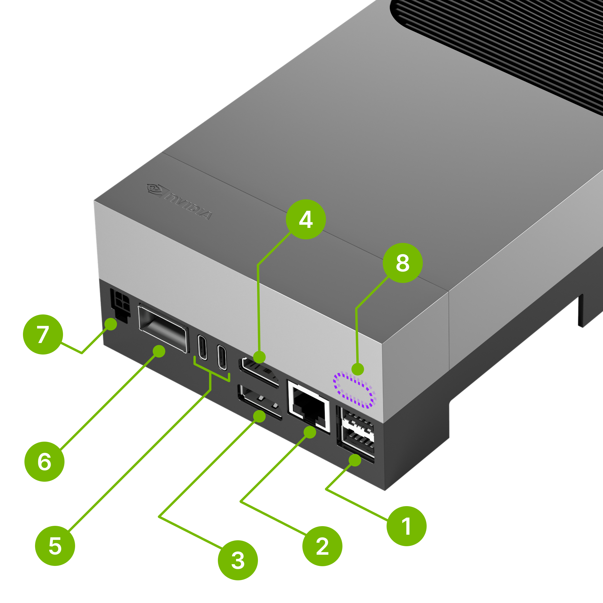
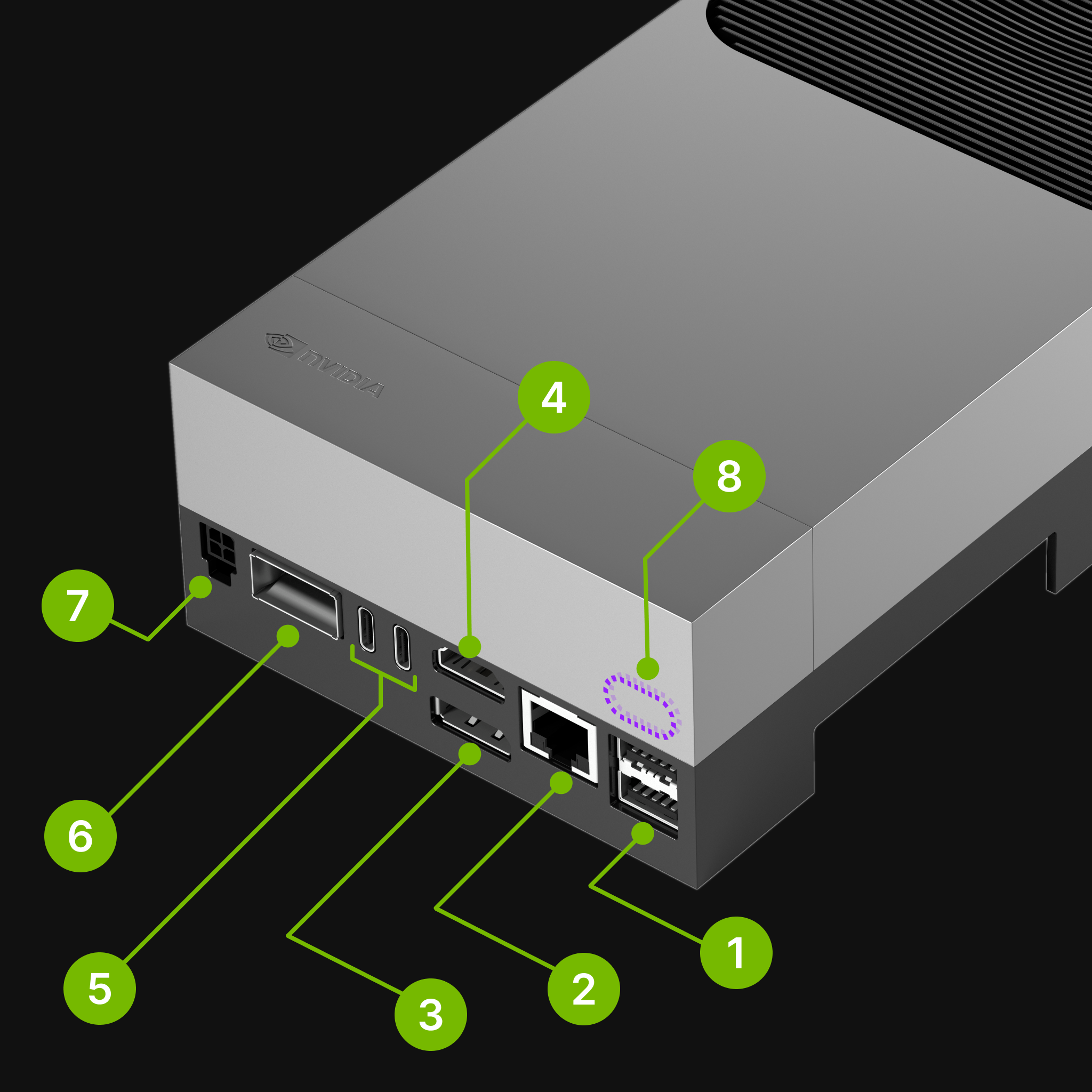
Mark. |
Name |
Note |
|
|---|---|---|---|
1 |
USB Type-A ports (2x) |
USB 3.2 Gen 2 (10Gbps) |
|
2 |
RJ45 Ethernet port |
5Gbps |
|
3 |
DisplayPort output |
||
4 |
HDMI output |
||
5 |
USB-C ports (2x) |
|
|
6 |
QSFP28 cage |
4x 25Gbps |
|
7 |
Micro-fit power input |
9-28V DC input (Up to 8A) |
|
8 |
Debug USB-C port |
(Behind the lid cover) |
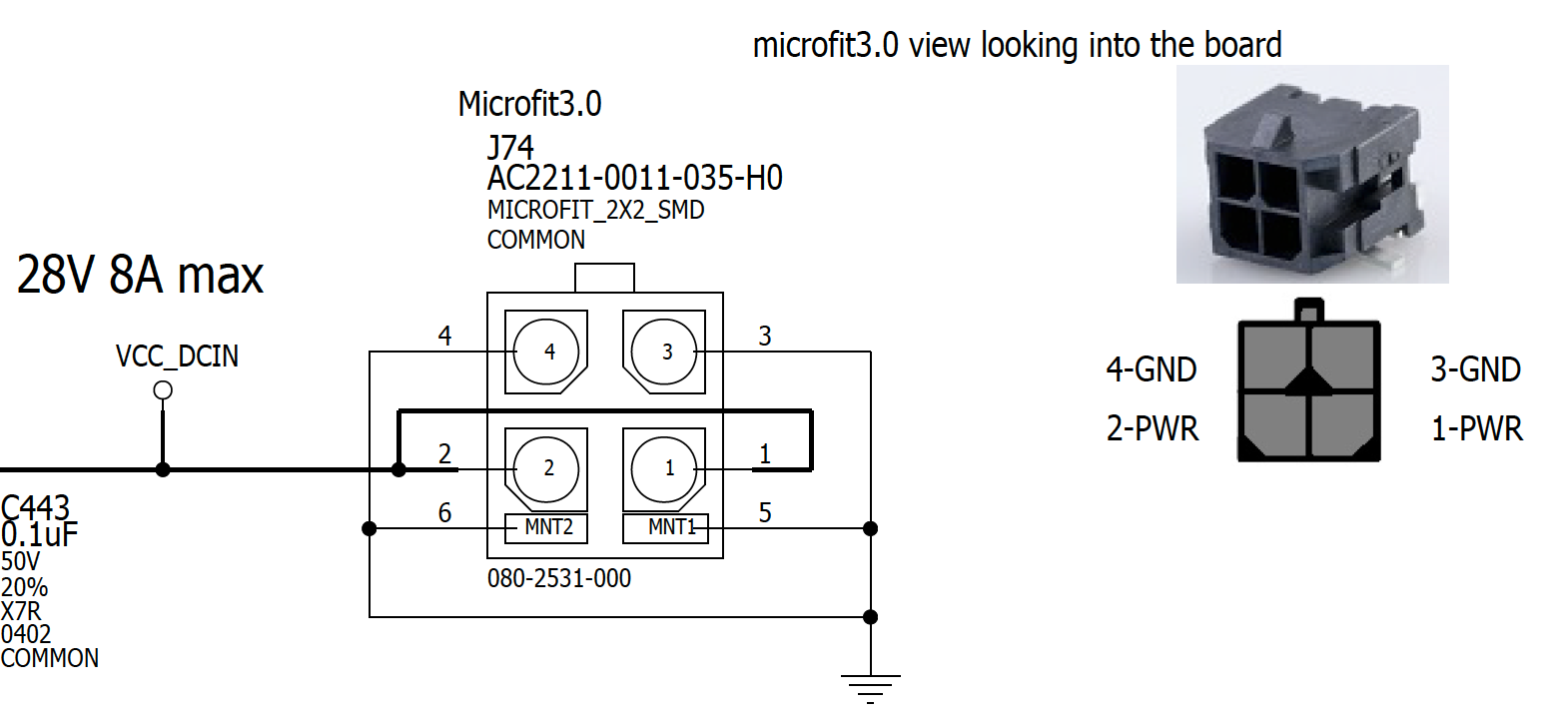
Micro-fit Power Connector Specification#
Pin Assignment#
Button Side Layout#


Mark. |
Name |
Note |
|
|---|---|---|---|
11 |
Power button |
||
12 |
Force Recovery button |
||
13 |
Reset button |
||
14 |
White LED |
How to enter Force Recovery Mode#
To enter Force Recovery Mode, follow the instructions below:
Press and hold the Force Recovery button (12 , the middle button)
While the Force Recovery button is pressed, briefly press the Reset button (13 , the right button)
Let go the Force Recovery button
The board will reboot into Force Recovery Mode.
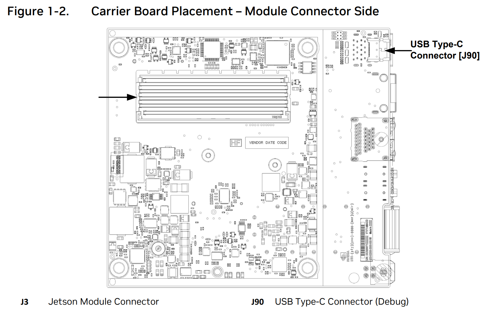
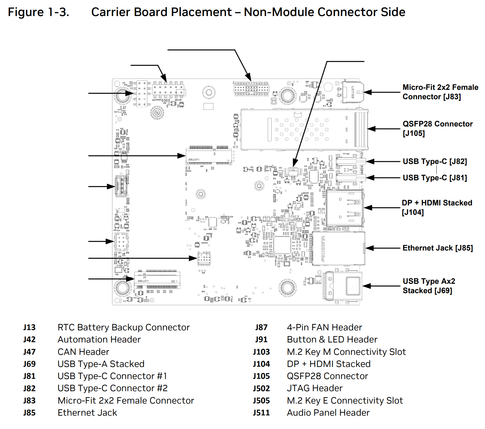
Carrier Board Layout#
Note
The diagrams below are from NVIDIA Jetson AGX Thor Developer Kit Carrier Board Specification v1.0.
Module Connector Side Layout#
Non-Module Connector Side Layout#
Label |
Name |
Details |
|
|---|---|---|---|
J103 |
M.2 Key M Connectivity Slot |
1TB NVMe SSD pre-populated |