Hardware Installation
Installation and initialization of the BlueField-2 BF2500 DPU Controller require attention to the mechanical, power, and precautions for rack-mounted equipment.
Safety warnings are provided here in the English language. For safety warnings in other languages, refer to the DPU Controller Installation Safety Instructions document available on the public website.
Please observe all safety warnings to avoid injury and prevent damage to system components. Note that not all warnings are relevant to all models.
Note that not all warnings may apply to all product models.

|
General Installation Instructions Read all installation instructions before connecting the equipment to the power source. |

|
Jewelry Removal Warning Before you install or remove equipment that is connected to power lines, remove jewelry such as bracelets, necklaces, rings, watches and so on. Metal objects heat up when connected to power and ground and can meltdown, causing serious burns and/or welding the metal object to the terminals. |
|
|
Over-temperature This equipment should not be operated in an area with an ambient temperature exceeding the maximum recommended: 45°C (113°F). An airflow of 800LFM at this maximum ambient temperature is required for HCA cards and NICs. To guarantee proper airflow, allow at least 8cm (3 inches) of clearance around the ventilation openings. |
|
|
During Lightning - Electrical Hazard During periods of lightning activity, do not work on the equipment or connect or disconnect cables. |
|
|
Copper Cable Connecting/Disconnecting Some copper cables are heavy and not flexible, as such they should be carefully attached to or detached from the connectors. Refer to the cable manufacturer for special warnings and instructions. |
|
|
Equipment Installation This equipment should be installed, replaced, or serviced only by trained and qualified personnel. |
|
|
Equipment Disposal Disposal of this equipment should be in accordance to all national laws and regulations. |
|
|
Local and National Electrical Codes This equipment should be installed in compliance with local and national electrical codes. |

|
Hazardous Radiation Exposure
|
The installation procedure of BlueField-2 DPU Controller involves the following steps:
|
Step |
Procedure |
Direct Link |
|
1 |
Unpack the package and confirm that you have received all the required components |
Refer to Package Contents |
|
2 |
Check the system’s hardware and software requirements. |
Refer to System Requirements |
|
3 |
Pay attention to the airflow consideration within the JBOF system |
Refer to Airflow Requirements |
|
4 |
Follow the pre-installation checklist |
Refer to Pre-Installation Checklist |
|
5 |
Install the BF2500 DPU Controller in the JBOF system |
Refer to Installation Instructions |
|
7 |
Connect the external power supply to the BF2500 DPU Controller |
|
|
8 |
Power on the system |
|
|
9 |
Perform initial system bring-up |
|
Hardware Requirements
Unless otherwise specified, NVIDIA products are designed to work in an environmentally controlled data center with low levels of gaseous and dust (particulate) contamination.
The operating environment should meet severity level G1 as per ISA 71.04 for gaseous contamination and ISO 14644-1 class 8 for cleanliness level.
A system that supports PCI Express high power cards is required for installing the card.
The system should be able to support 75W through the PCIe x16 interface and an additional 75W through the ATX PCIe power connector
Airflow Requirements
BlueField-2 BF2500 DPU Controller is offered with one airflow pattern: from the BlueField-2 SoC to the network ports.
All systems in the same rack should be planned with the same airflow direction. All components need to have the same airflow direction.
Please refer to the Specifications section for airflow numbers for each specific card model.
Software Requirements
See Operating System under System Requirements section under the Introduction section.
Software Stacks - The BF2500 DPU Controller is shipped with Linux based Operating System burned on it which includes all needed drivers. For more information, please refer to the BlueField-2 Software User Manual.
Check System Requirements Overview under Introduction for more details.
The BF2500 card being installed in a system that operates with voltages that can be lethal. Before opening the case of the system, observe the following precautions to avoid injury and prevent damage to system components.
Remove any metallic objects from your hands and wrists.
Make sure to use only insulated tools.
Verify that the system is powered off and is unplugged.
It is strongly recommended to use an ESD strap or other antistatic devices.
1. Unpack the BF2500 DPU Controller
Unpack and remove the BF2500 DPU Controller. Check against the package contents list that all the parts have been sent. Check the parts for visible damage that may have occurred during shipping. Please note that the cards must be placed on an antistatic surface. For package contents please refer to Package Contents.
Please note that if the card is removed hastily from the antistatic bag, the plastic ziplock may harm the EMI fingers on the QSFP56 connector. Carefully remove the card from the antistatic bag to avoid damaging the EMI fingers.
2. Turn off the power to the JBOF system.
Turn off the power to the JBOF system, and disconnect the power cord and remove the cover. Refer to the JBOF system documentation for instructions. Before you install the BF2500 DPU Controller, make sure that the system is disconnected from power and any networks.
This section provides detailed instructions on how to install your BlueField-2 2500 DPU Controller in a system.
The BlueField-2 BF2500 DPU Controller should be installed only in a JBOF System as it functions as a PCIe root-complex (RC) initiating PCIe bus operations. Installing it in a regular host system may damage the card.
Please note that the following figures are for illustration purposes only.
Step 1. Open the system case.
Step 2. Locate an available PCI Express x16 slot.
Step 3. Applying even pressure at both corners of the card, insert the BF2500 DPU Controller in a PCI Express slot until firmly seated.
Step 4. Secure the bracket to the system with the bracket screw.
Step 5. Close the system case
Networking Cables
All networking cables can be inserted or removed with the unit powered on.
To insert a cable, press the connector into the port receptacle until the connector is firmly seated.
Support the weight of the cable before connecting the cable to the adapter card. Do this by using a cable holder or tying the cable to the rack.
Determine the correct orientation of the connector to the card before inserting the connector. Do not try and insert the connector upside down. This may damage the adapter card.
Insert the connector into the adapter card. Be careful to insert the connector straight into the cage. Do not apply any torque, up or down, to the connector cage in the adapter card.
Verify that the connector locks in place.
WarningWhen installing cables make sure that the latches engage.
ImportantAlways install and remove cables by pushing or pulling the cable and connector in a straight line with the card.
After inserting a cable into a port, the Amber LED indicator will light when the physical connection is established (that is, when the unit is powered on and a cable is plugged into the port with the other end of the connector plugged into a functioning port).
After plugging in a cable, lock the connector using the latching mechanism particular to the cable vendor. When data is being transferred the Green LED will blink. See Networking LED Interfaces.
Care should be taken as not to impede the air exhaust flow through the ventilation holes. Use cable lengths that allow for routing horizontally around to the side of the chassis before bending upward or downward in the rack.
To remove a cable, disengage the locks and slowly pull the connector away from the port receptacle. The LED indicator will turn off when the cable is unseated.
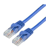
RJ45 Cable for the 1GbE OOB Management Interface
NOTE: A CAT5 cable should be used.
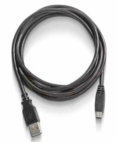
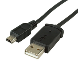
USB Interface Cabling
Debugging and loading new versions of the operating systems and firmware requires the use of Type A to Type B mini-USB 2.0 Cable. The following figure shows an example of a cable with a USB Type A connector on one end an a mini-USB Type B connector on the other.