Introduction
The Mellanox CS8500 switch system provides the highest performing fabric solution by delivering high bandwidth and low latency to enterprise data centers (EDC), high-performance computing (HPC) and embedded environments. Built using the latest generation of Mellanox Quantum™ technology, the CS8500 system is equipped with 800 ports with up to 200Gb/s full bidirectional bandwidth per port, all while maintaining a compact form factor of a standard 29U rack.
The Mellanox Quantum based switch system is the world's smartest network switch, designed to enable in-network computing through Mellanox Scalable Hierarchical Aggregation Protocol (SHARP)™ technology which enables the usage of all active data center devices to accelerate the communication frameworks.
The system's quad-core x86 CPU comes with an on-board Subnet Manager, enabling simple out-of-the-box fabric bring-up for up to 2048 nodes. When used in conjunction with Mellanox ConnectX®-6 adapter cards, this Mellanox Quantum based switch system can achieve up to 1600 ports of HDR100 100Gb/s by utilizing two pairs of two SerDes lanes per port, making it the highest density chassis switch system available on the market.
Networks which utilize the CS8500 system can carry converged traffic with the combination of ensured bandwidth and granular quality of service.
The CS8500 runs the same MLNX-OS® software package that is running on Mellanox InfiniBand FDR and EDR products to deliver a complete and familiar chassis management of the firmware, power supplies, fans and ports, and ensure interoperability with the previous generation of systems. Mellanox switch systems can also be coupled with Mellanox Unified Fabric Manager (UFM®) software for managing scale-out InfiniBand computing environments. The UFM software enables data center operators to efficiently provision, monitor and operate the modern data center fabric. It can also boost application performance and ensures the fabric is up and running at all times.
This switch system uses liquid cooling methods with a 4U tall in-rack Coolant Distribution Unit (CDU) isolating the internal water loop cooling the components from the water loop connected to the data center facilities. Customers without water cooling facilities can opt for a Water-to-Air Heat exchanger (AHX) which is purchased separately. Mellanox provides fully tested and certified CDU and AHX units. More information regarding the system cooling methods can be found in the System Cooling Design chapter.
The installation process is covered in detail in the CS8500 Hardware Installation user manual. Please contact Mellanox support for more information.
Features List
800 HDR (200Gb/s) or 1600 HDR100 (100Gb/s) InfiniBand ports in a 29U switch
320 Tb/s aggregate data switching capacity with ultra low latency
IBTA spec rev 1.3.1 and 1.2.1 compliant
Ultra low switch latency
Liquid cooling with separate loop
Optional AHX for installation in air cooled data centers
N+1 or N+N redundant and hot-swappable power supplies
80+ Platinum and Energy Star certified power supplies
x86 ComEx Broadwell CPU
7” touch screen for port status visibility
The switch itself is 29U tall but requires an extra 1U to install the shelf.
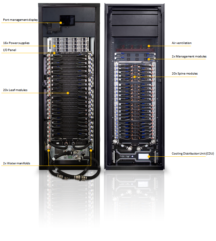
The switch ships in a minimum base configuration plus additional modules depending on the ordered customer configuration. Minimum base configuration included modules::
2x Management modules
20x Spine modules (max)
20x Leaf modules (max)
16x Power Supplies (max)
CDU or AHX (based on data center facilities)
Power Supply Redundancy
The CS8500 system ships with 9 power supplies as standard but requires a minimum of 8 PSUs for proper operation. This provides the system with sufficient N+1 redundancy to ensure the system keeps operating without degradation in case of a single PSU failure.
The following redundancy options are available:
No redundancy (combined mode)
All available PSUs are assigned to service the power budget. At maximum capacity, 8 PSUs are required but will not provide any failover. Any additional PSU added to the switch will raise the Power Budget and will be used for failover. If the number of active PSUs cannot maintain a power budget larger than the maximum consumed power of all turned on modules, an "insufficientPower" warning will be sent and the software will turn off the FRUs.N+1 Mode (ps-redundant)
In this mode, one of the PSUs is reserved in the event of a failover. At maximum capacity, 9 PSUs are required. When 8 PSUs are operating, the switch will send a "low Power" warning but continue to operate at maximum capacity.N+N configuration (grid-redundant mode)
Customers who wish to get N+N redundancy should acquire 7 additional PSUs for an overall total of 16 PSUs. The power supplies in “grid-redundant” mode are split into two logical power supply grids. The first half of the PSUs belong to grid A (PSUs #1 – #8) and the second half to grid B (PSUs #9 - #16).
The systems can work with only one grid and will utilize the minimum power budget between Grid A and Grid B.ImportantN+N redundancy only works with a supply voltage of 220V.
The second power grid can be supplied by any of the following:
A backup power supply grid
A generator
A battery backup system
Any combination of the above
Connecting 8 power supplies to one power supply grid and the remaining 8 power supplies to a secondary power supply grid will create N+N redundancy. This is high availability. Under these conditions, should a power grid fail (an electric company power failure or blackout, for example) power grid high availability will continue to keep the chassis running at full capacity through the secondary or backup power supply grid.
When the power drops below the required minimum due to power supply failure, MLNX-OS® may power down some leafs. If this happens, it may be necessary to reboot the chassis once the defective PSU has been replaced. Two methods to reboot are to use the reboot command in the CLI or reboot through the WebUI.
Software definition for power redundancy mode should reflect the real implementation to allow the expected system behavior, please refer to MLX-OS command reference for further details.
AC Source Requirements
The CS8500 system supports 200-240VAC 50/60Hz operation only. 110VAC source is not supported. Each AC source should be capable of providing a maximum of 16A input current. Each PSU has a built-in C20 inlet socket, which matches the AC cable provided with the system. Customers shall use PDUs with C19 sockets to allow system connection to AC power. The switch itself is 29U tall but requires an extra 1U to install the shelf.