System Cooling Design Overview
The Mellanox Quantum-based director switch system implements a hybrid approach to manage its thermal performance where 90% of heat is dissipated by liquid cooling while the other 10% is dissipated using a traditional air cooling solution. The Leaf and Spine modules are cooled with a liquid solution, while the Management modules and Power supplies are cooled with air flow.
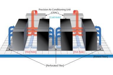
The air flow of all relevant components is aligned and moves from the front side of the system (Spine side) to the rear side (Leaf side) – the rack should be positioned in the correct orientation to allow the Spine side to absorb the cold air within the data-center cold aisle, and push the hot air from the system’s Leaf side to the hot aisle. The upper side of the system hosts the perforated air panel which must not be blocked to allow proper cooling for the power supplies.
Each PSU unit is having built in fan, PSU itself controls the fan speed to meet its thermal performance. Fan health is reported to system MNG for monitoring.
MNG FRU contains 5 fans:
3 fans at the front panel are responsible for MNG module cooling. There is 1 fan redundancy, so the module will continue proper operation in case of single fan failure. Fans of both management modules are synced to the same speed through the SW thermal algorithm. Its health status is monitored by SW.
2 additional fans are located at the back side of the management module. Those fans are 1+1 redundant and are responsible to avoid air stagnation within the chassis. Those fans are rotating at fixed speed. Its health status is monitored by SW.
It is important to install the blank module units in all the unused slots, to ensure correct air flow and proper thermal management within the system.
It is important to insure the system gets the required amount of external air flow for optimal thermal performance. Refer to Specification Appendix for air temperature requirements and CFM limitations.
Liquid Cooling Design
The water-based coolant used in this system, transfers heat from the internal hot components to the external heat exchanger. There are two methods to dissipate heat:
Water-to-Water heat exchanger
Water-to-Air heat exchanger
The selection of the heat exchanger depends on the customer's data center facilities.
Data centers which support water cooling facilities should use water-water heat exchanger providing greater power and real estate saving as well as noise emission reduction. The overall setup of this solution allows the switch and the water-to-water heat exchanger to be installed within the same rack without any extra space requirements.
Water-to-Water Heat Exchanger
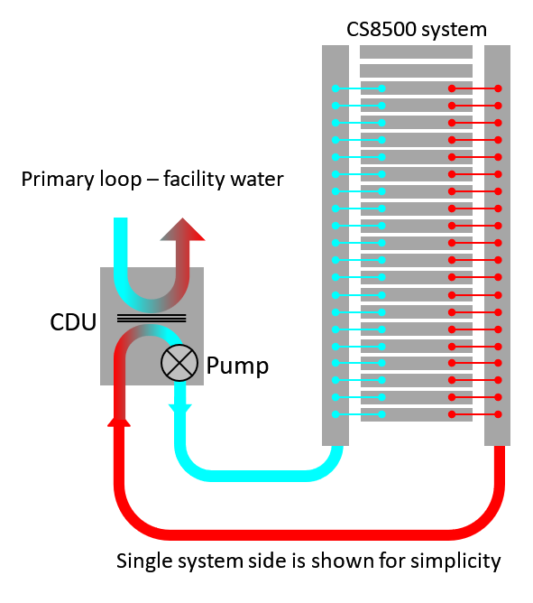
The water-to-water heat exchanger is called a Cooling Distribution Unit (CDU). The below diagram illustrates the heat flow within this setup:
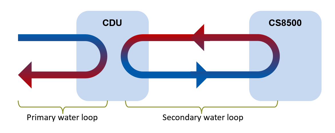
The water in the primary and secondary loops are not mixed within the CDU. Each one of the loops has its own requirements that should be met to allow proper system performance.
The water in the secondary loop complies with very stringent quality requirements. It is used to cool the electronic components directly.
The water in the primary loop is the facility’s water. It circulates through the CDU heat exchanger only. The quality of the water in this loop should be monitored and maintained by the customer but the quality standards for this loop in overall are more relaxed compared to those of secondary loop.
During primary water loop design customer should follow ASHRAE standard recommendations. To design reliable primary water loop customer should consider the following:
CDU wetted material and its compatibility to the test of wetted materials within the loop and insure that selected coolant can efficiently control corrosion processes, in particular galvanic corrosion
CDU maximum allowed pressure must not be exceeded at any circumstances
The required flow rate depending on water temperature
Mechanical design of primary water attachment to allow easy maintenance, access and possible replacement of CDU
The main CDU features are:
Redundant PSU (1+1)
Redundant pump (2+1)
Internal 50 micron filter
Drain/Fill port without internal pump
Pressure release valve
External IF: ModBus TCP via std RJ45 connector
Max power dissipation: 500W
Full set of telemetry
5-liter internal reservoir
More information regarding the CDU can be found in the Mellanox CS8500 Cooling Solution Maintenance User Manual.
The CDU is standalone unit which operates completely independently. it is neither connected nor controlled by Mellanox switches. The CDU's external ModBus TCP interface can be connected to an external management network for 24/7 monitoring of the equipment.
The CDU is intended to be installed within the same rack with the switch. It is possible to install the CDU above or below the chassis depending on water facilities design.
facilities hoses located under the floor assumes bottom CDU installation while facilities with hoses located above the rack will utilize upper CDU installation. Side mounted CDU will be connected to either the bottom or upper manifolds’ sides – see the secondary loop description below.
Water-to-Air Heat Exchanger
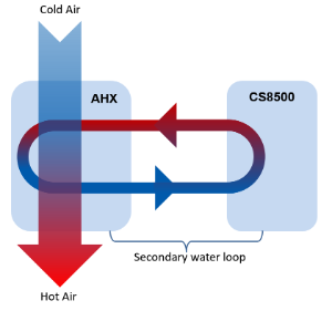
If water cooling facilities are not available at the data center, the water-to-air heat exchanger should be used. This solution allows the customer to use the system within the standard cold-hot aisle data center environment.
The below diagrams illustrate the main components and the heat flow within this setup:
The main AHX features are:
Redundant PSU (1+1)
Redundant pump (1+1)
Redundant fan (3+1)
Internal 50-micron filter
Drain/Fill port without internal pump
External IF: ModBus TCP via std. RJ45 connector
Power dissipation: 1200W
Full set of telemetry
7-liter internal reservoir
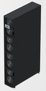
Mech form factor: slim rack
42U height
350mm width
1000mm depth
FRUs: PSU, Pump, Fan
Only trained personnel are allowed to open the unit and replace FRUs.
The AHX is standalone unit which operates completely independently. it is neither connected nor controlled by Mellanox switches. The AHX's external ModBus TCP interface can be connected to an external management network for 24/7 monitoring of the equipment.
The heat exchanger in this case will be placed vertically on the side of the switch system. Both above the rack and below the floor AHX to Switch hoses connectivity are supported but will require additional space.
The Water cooling components are installed within the rack as part of the chassis installation which is performed by Mellanox trained personnel only. The water cooling infrastructure provides water access to both sides on the chassis where the Leafs and Spines are installed.
The below diagram illustrates the main components of this setup:
The Leaf and Spine hoses are not shown to not obscure the main components of this setup.
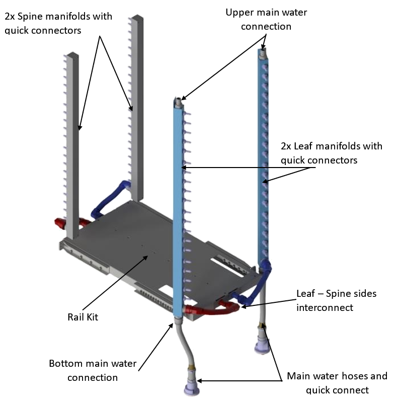
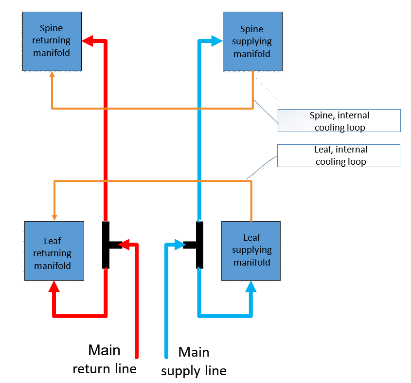
The Leaf and Spine modules are connected between the cold and hot manifolds, heating the water and closing the water loop. Water flow is achieved by redundant pumps located within the CDU unit. (See below diagram)
The coolant solution is an important part of the system. It takes care of common water related issues and guarantees a long term reliable system operation.
A ready-to-use PG-25 coolant is used for this system. It is an inhibited organic oil solution with 25% propylene glycol which acts as a natural biocide.
Personal protective equipment such as goggles and gloves must be used while working with the coolant. The coolant is not defined as a hazardous material, but it is highly recommended to read its MSDS (Materials Safety Data Sheet) to respond properly if exposed to it.
PG-25 does not require any additional chemicals to be added or to be diluted – it should be used as is. Refer to PG-25 technical and safety datasheets for further information.