LED Status Indicators
The LEDs are placed on the chassis for the convenience of the IT manager. All chassis conditions and management options are available and controllable through the management software, either CLI or WebUI.
It is recommended that all of the chassis subsystems be maintained and managed through the management software.
The PSUs are on the Leaf side of the chassis at its upper side. There is one bicolor LED located on PSU to show its status. Table below describes LED behavior.
Power Supply Unit Status Indications
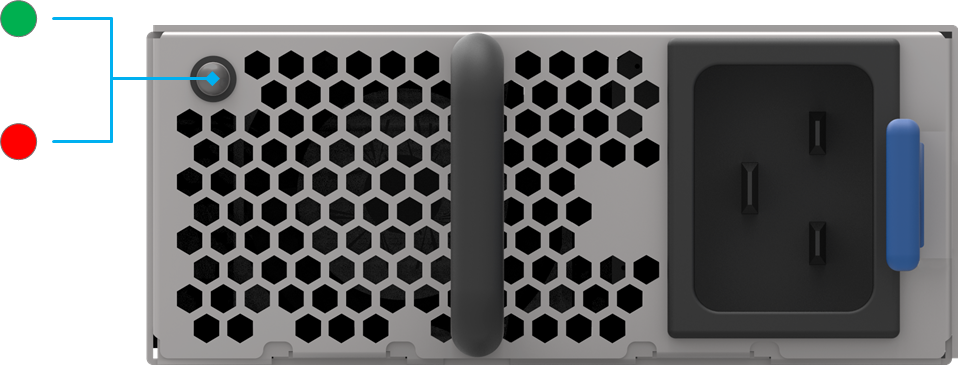
Power Supply Condition | Green LED | Amber LED |
No AC to all power supplies. | Off | Off |
Power supply critical event causing a shutdown; failure, OCP,OVP,Fan fail, OTP, UVP. | Off | Amber |
Power supply warning events where the power supply continues to operate; high temp (inlet temperature > Inlet OT warning, or hot spot temperature > Hotspot OT warning, high power, high current, slow fan (<1200rpm). | Off | 0.5Hz Blink Amber |
AC presents only 12VSB on "PS off" or PS in Smart Redundant state. | 0.5Hz Blink Green | Off |
Output ON and OK. | On | Off |
AC cord unplugged. | Off | Amber |
CS8500 PSU Cover
Status LED
The Status LED is located in the middle of the leaf to allow easier visibility when all cables are installed.
The leaf Status indicator LED has the following LED assignment:
LED Condition | Description |
Off | No power to the leaf |
Green: Solid | Leaf is up and running |
Green: Flashing | Leaf is booting or being restored to factory default |
The status LED indicator in systems earlier than REV-AD00 will flash when the Leaf is turned off.
UID LED Switch Identifier
The UID LED is a debug feature that will become available to customers in the near future. For details please contact Mellanox Technologies support.
LED Condition | Description |
Off | UID LED inactive (default) |
Blue: Solid | UID LED activated |
Leaf Module Port Connector LED Assignment
Leaf design do not have per port fabric led indication. All port/link related data can be observed on system’s LCD screen.
The status LEDs for the spine and their descriptions are shown in the table below. The LEDs indicate as follows.
Status LED
The table below shows the spine status according to the LED condition:
LED Condition | Description |
Off | No power to the spine |
Green: Solid | Spine is up and running |
Green: Flashing | Spine is powering up or being restored to factory default |
The status LED indicator in systems earlier than REV-AC00 will flash when the Spine is turned off.
UID LED Switch Identifier
UID LED is user activated and allows easier FRU spotting if any maintenance or attention is required.
LED Condition | Description |
Off | UID LED inactive (default) |
Blue: Solid | UID LED activated |
Spine to Leaf IB Connection Status LEDs
Spine design do not have per port fabric led indication. All port/link related data can be observed on system’s LCD screen.
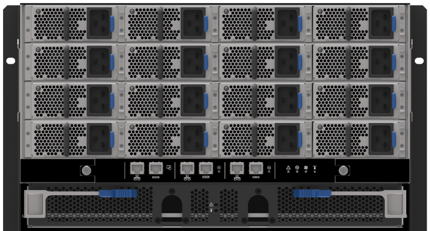
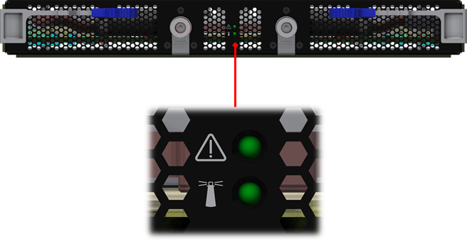
Spine side IO Panel LED Indicators
The spine side panel display has LEDs that show the chassis condition.
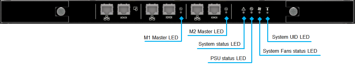
LED | Condition | Description | Normal State |
Status 
| Off | No power | Green |
Green | System is up and running | ||
Green: Flashing | System booting/restore factory default in progress | ||
PSU Status 
| Off | No power | Green |
Green | Normal operational | ||
Amber | PS fault detected – check individual power supplies for fault indications | ||
Fan Status 
| Off | No power | Green |
Green | Normal operation | ||
Amber | Fatal error in one or more of the fans | ||
MNG1 Master Status 
| Off |
| Green |
Green | Management module is up and operating as master | ||
MNG2 Master Status 
| Off |
| Off |
Green | Management module is up and operating as master | ||
UID LED 
| Off |
| Off |
Blue | System/FRU visual identification is active |
Management Module LED Indicators
Below is a diagram detailing the LED indicators on the management module.
Management Module Indicators
Management LED Display for Normal Operation
LED | Condition | Description | Normal State |
Status LED: Shows the status of the system.
| Off | No power | Green |
Green | System is up and running | ||
Green: Flash- ing | System booting/restore factory default in progress | ||
Amber | System error – attention needed (e.g. overheating, diagnostics fail, CPU hang, HW fail, overheat-critical) | ||
PSU Status
| Off | No power | Green |
Green | Normal operation | ||
Amber | PS fault detected – check individual power supplies for fault indications | ||
Fan Status
| Off | No power | Green |
Green | Normal operation | ||
Amber | Fatal error in one or more of the spine fans – check individual spine fan LEDs for fault indications | ||
Master 
| Off | This management module is not the master | Green |
Green | Management module is operating as a master | ||
UID
| Off | System level UID LED is not active | |
Blue | System level UID LED activated | Off |