Management Module Interfaces
The switch system requires at least one management module. The 2nd MNG module can provide system management redundancy for the users that high availability is required.
The location of the MNG modules are on the Spine side of the system thus there is no enough space for cables routing to MNG modules. For this reason, all MNG communication interface was moved to IO board located on the Leaf side. MNG front panel is having few monitoring and debug interfaces yet.
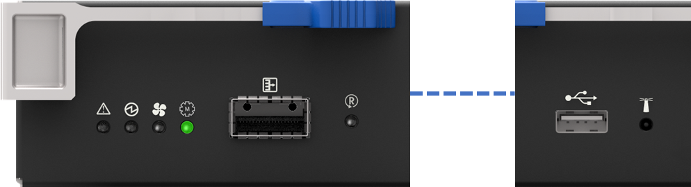
MNG FRU external interface:
Status LEDs
QSFP debug port – do not use and do not connect anything to this port. Connecting to this port may disrupt proper system operation
1 USB 2.0 port
1 RST – reset button
1 MAC label
Management Module Interfaces
The console port is used during the installation process to configure the chassis for remote management. Connect this port to a local host using the harness supplied with the chassis. See the MLNX-OS® User Manual for the initial configuration procedure. RS232 connection should be configured for 115200Kb baud-rate.
Apart from the initial configuration, I²C interface is made exclusively for debugging and troubleshooting. Only FAEs are authorized to connect through it.
Only original Mellanox cables that are supplied with the FRU can be used to connect the switch system to the server.
Refer to the Replacement Parts appendix for harness details.
Using uncertified cables may damage the I²C interface.
The management ports are 1Gb/s Ethernet (1GbE) ports for remote management. Any remote terminal connected to the Ethernet port can then be used to manage the fabric and chassis.
The USB 2.0 port can be used to upload new software using any storage device that has a USB connector.
The Reset button resets the chassis management module when the button is pushed. When the button is held down for 15 seconds the management module is reset and the password deleted.
On a switch system with two management modules, the slave management module must be extracted, then the aforementioned procedure must be performed on the master management module. Once the system reloads, the slave management module may be reinserted.
Do not use a sharp pointed object such as needle or push pin for pressing the Reset button. Sharp objects can cause damage, use a flat object such as a paper clip.
This button resets the CPU of the management module. A quick push of this button performs this reset. When the reset button is pushed on the master management module, the management module is reset becoming the slave and the other management module becomes the master. If there is only one management module in the chassis all of the leafs and ports are reset by bringing them down and powering them up when the reset button is pushed. When the button is held down for 15 seconds the management module is reset and the password is deleted. You will then be able to enter without a password and make a new password for the user “admin”.
RJ-45 Console and I²C interfaces are integrated in the same connector.
RJ-45 CONSOLE and I²C Pinout
Signal | Pin# | Color |
Not connected | 1 | G/W |
I²C_SCL | 2 | G |
TXD | 3 | O/W |
Not connected | 4 | Bl |
GND | 5 | Bl/W |
RXD | 6 | O |
I²C_SDA | 7 | Br/W |
Not connected | 8 | Br |
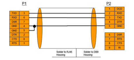
RS232 harness cable (DB9 to RJ45) is supplied to connect a host PC to the switch’s RJ-45 Console port.
RJ45 to DB9 Harness Pinout