Configuration Scenarios
Mellanox BlueField BF1600 Controller Cards offer a variety of options to serve the requirements of high-density and high-performance storage environments. The following section describes various connectivity options for NVMe SSDs. This list of scenarios is not exhaustive (represents the maximum utilization of PCIe connectivity), but it shows some different available options. Each scenario includes a view of the required cabling between the BF1600 Controller Card and the system platform.
Configuration | PCIe Switch | No. SSDs | No. of Auxiliary Raisers | No. of Cabline- CA II PLUS Harnesses | BlueField PCIe Bifurcation, Speed PCIe Golden Fingers Connector | BlueField PCIe Bifurcation, Speed PCIe Auxiliary Connector |
No | 4-8 | 0 | 0 | 4 x Gen 3.0/4.0 x4 | 0 | |
No | 8-16 | 1 | 2 | 4 x Gen 3.0/4.0 x4 | 4 x Gen 3.0 x 4 | |
Yes | 8-16 | 1 | 2 | 1 x Gen 3.0/4.0 x16 | 1 x Gen 3.0 x16 | |
Yes | 24 | 1 | 2 | 1 x Gen 3.0/4.0 x16 | 1 x Gen 3.0 x16 |
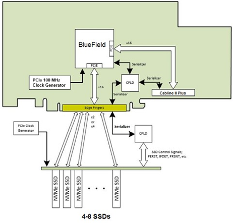
For direct connectivity to 4-8 SSDs configuration, the first BlueField PCIe Gen 4.0 x16 interface is routed through the x16 PCIe Gen 3.0/4.0 Edge Connector towards the first group of four x4 SSDs or eight x2 SSDs. The control signals for each NVMe SSDs are routed through a serialized bus that is connected from the BlueField to the CPLD and further-on towards the PCIe edge connector. The user should implement a CPLD expander on its NVMe SSDs backplane and expand the various control signals towards each of the 4-8 SSDs.
The BlueField and the NVMe SSDs are implementing separate clock schemes, thus, the user should drive the 100Mhz reference clock for the SSDs from its own clock source.
See the below figure for an illustration of the 4-8 NVMe SSDs configuration.
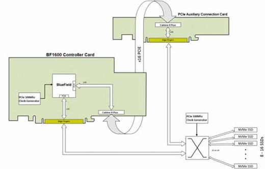
For direct connectivity to 8-16 SSDs configuration, the first BlueField PCIe Gen 4.0 x16 inter- face is routed through the x16 PCIe Gen 3.0/4.0 Edge Connector towards the first group of four x4 SSDs or eight x2 SSDs. The second BlueField PCIe Gen 4.0 x16 interface is routed through the x16 PCIe Gen 3.0 only CABLINE-CA II PLUS connector towards the second group of four x4 SSDs or eight x2 SSDs.
The control signals for the each NVMe SSDs is routed through a serialized bus that is connected from the BlueField to the CPLD and further-on towards the PCIe edge connector and the CABLINE-CA II Plus harness. The control signals are separated inside the CPLD to the appropriate groups to match each NVMe SSD backplane.
The user should implement a CPLD expender on each of its NVMe SSDs backplanes and expand the various control signals towards each of the 4-8 SSDs.
The BlueField and the NVMe SSDs are implementing separate clock schemes, thus the user should drive the 100Mhz reference clock for the SSDs from its own clock source.
See the below figure for an illustration of the 8-16 NVMe SSDs configuration.
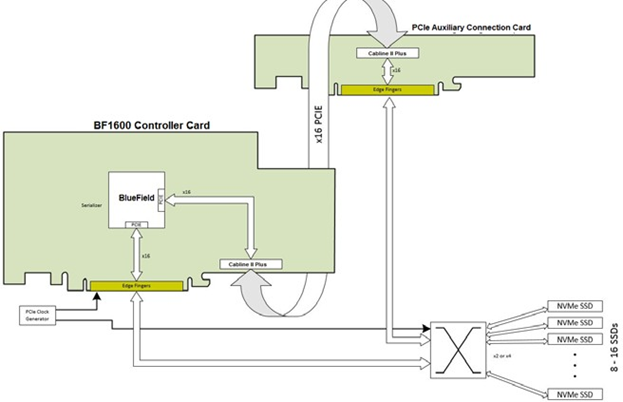
For 18-6 SSDs configuration with an external PCIe switch, the first BlueField PCIe Gen 3./4.0 x16 interface is routed through the x16 PCIe Gen 3.0/4.0 Edge Connector toward the first x16 port of the PCIe switch. The second BlueField PCIe Gen 3.0 x16 interface is routed through the PCIe Gen 3.0 CABLINE-CA II PLUS connector and the PCIe Auxiliary Card towards the sec- ond x16 port of the PCIe Switch.
See the below figure for an illustration of the 16 NVMe SSDs configuration.
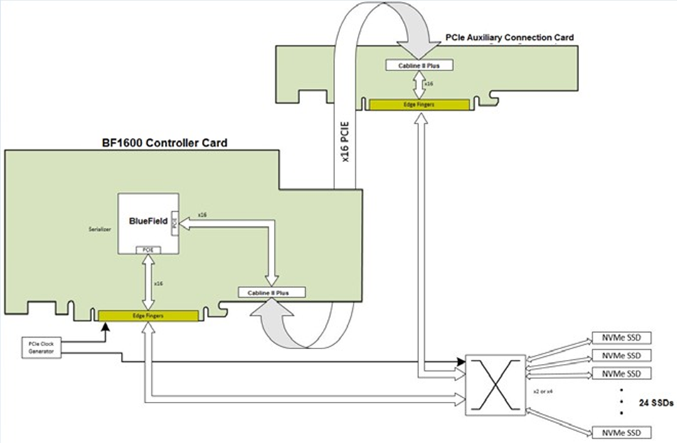
For connectivity to 24 SSDs configuration with an external PCIe switch, the first BlueField PCIe Gen 4.0 x16 interface is routed through the x16 PCIe Gen 3.0/4.0 Edge Connector toward the first port of the x16 external PCIe switch. The second BlueField PCIe Gen 4.0 x16 interface is routed through the PCIe Gen 3.0 CABLINE-CA II PLUS connector and the PCIe Auxiliary Card towards the second port of the x16 external PCIe switch.
See the below figure for an illustration of the 24 NVMe SSDs configuration.
The BlueField BF1600 Controller Card implements a “separate clocking scheme”. The Controller Card has a dedicated 100MHz oscillator clock source for feeding its PCIe reference clock. This clock is not driven out of the card and it is expected that the downstream PCIe entities will have their own clock source.